Table of Contents
Advertisement
Quick Links
Advertisement
Table of Contents

Related Manuals for Argus ALPHA OUTBACK ENERGY Cordex 48-1kW

Summary of Contents for Argus ALPHA OUTBACK ENERGY Cordex 48-1kW
- Page 1 Cordex 48-1kW 19" Shelf, Flush Mounting Up To 3000W With Distribution 030-713-B2...
- Page 2 This page intentionally left blank. Worldwide Corporate Offices Headquarter Germany France and Benelux Eastern Europe Russia fbnl@alpha-outback-energy.com russia@alpha-outback-energy.com ee@alpha-outback-energy.com Hansastrasse 8 D-91126 Schwabach Tel: +49 9122 79889 0 Middle East Spain Africa Fax: +49 9122 79889 21 me@alpha-outback-energy.com spain@alpha-outback-energy.com africa@alpha-outback-energy.com Mail: info@alpha-outback-energy.com Alpha and Outback Energy GmbH reserves the right to make changes to the products and information contained in this document without notice.
- Page 3 Cordex 48-1kW 19” Shelf, Flush Mounting Systems Up To 3000W With Distribution 030-713-B2 The following documents and drawings are included in this manual to provide the necessary information required for installation, operation and fault diagnosis of the unit: • Specifications, 19” Shelf: 030-713-B1 •...
- Page 4 Specifications for Argus’ Cordex 48-1kW 19" Shelf System Basic Unit, Shelf Maximum Output: 62.4A, 58Vdc Recommended Feeder Breaker Single Phase: 15A, #12AWG, 90 deg.C wire at 30 deg. C ambient (per rectifier) Mechanical Dimensions: 177.1mm H x 444.5mm W x 303.4mm D (rectifier front panel 18.5mm D) [6.97"...
- Page 5 Specifications for Argus’ Cordex 48-1kW 19" Shelf System Continued Basic Unit, CXCM Input Voltage: 17 to 65Vdc within rated limits Current: <100mA @ 48Vdc <200mA @ 24Vdc MTBF: >430,000 hours @ 30°C (86°F) EMC: The unit meets requirements of: ICES-003 Class B...
- Page 6 Specifications for Argus’ Cordex 48-1kW 19" Shelf System Continued Hardware Specifications, CXCM CPU: Coldfire RAM: Flash: 4MB standard, 8MB optional Display: 160 x 160 pixel grayscale LCD Front Panel Controls: Reset button and touch panel (display and input device) LED’s:...
- Page 7 Specifications for Argus’ Switched Mode Rectifier Cordex 48-1kW Power Module Output Voltage: 40.5 to 58Vdc within rated limits Current: 18.5A @ 54Vdc nominal (20.8A maximum @ 48V) Maximum Power: 1000W continuous/module Static Load Regulation: Better than ±0.5% for any load change within rated limits Dynamic Load Regulation: Better than ±2% for 10% - 90% load step...
- Page 8 Specifications for Argus’ Switched Mode Rectifier Cordex 48-1kW Continued Power Module Input Voltage: 208 to 240Vac nominal Extended Operation: Low: 150 to 90Vac (power de-rated linearly to 40% output) High: 176 to 320Vac (de-rated power factor above 265Vac) Frequency: 50/60Hz nominal (45 to 66Hz) Current: 5.3 to 4.6A (nominal Vac)
- Page 9 Specifications for Argus’ Switched Mode Rectifier Cordex 48-1kW Continued Referenced Standards EN 300 386-2 EMC and ERM; Telecommunication Network Equipment EN 55022 (CISPR 22): 1998 Information Technology Equipment – Radio Disturbance Characteristics – Limits and Methods of Measurement EN 61000-3-2:2000...
- Page 10 US and Canadian markets, to the applicable US and Canadian standards. (1) Argus rectifier and power system products, bearing the aforementioned CSA marks, are certified to CSA C22.2 No. 950 and UL 1950, or CSA/UL 60950.
- Page 11 IMPORTANT SAFETY INSTRUCTIONS SAVE THESE INSTRUCTIONS 1. Please read this manual prior to use to become familiar with the product’s numerous features and operating procedures. To obtain a maximum degree of safety, follow the sequences as outlined. 2. This manual provides warnings and special notes for the user: a.
-
Page 12: Table Of Contents
ABLE OF ONTENTS ................................1 NTRODUCTION Scope of the Manual ............................. 1 Product Overview............................1 Part Numbers and List Options........................2 ..............................3 ECTIFIER EATURES Front Panel..............................3 Rear Panel ..............................4 True Module Fail Alarm..........................4 Heat Dissipation ............................4 Over Temperature Protection ........................ - Page 13 ................................18 PERATION Main Rectifier States ........................... 18 Main Rectifier Modes ..........................19 Can Bus Communications........................... 19 Factory Ranges and Defaults ........................20 ..............................21 YSTEM TARTUP Check System Connections ........................21 Verify AC and Power the Shelf ........................21 Check Battery Polarity and Connect ......................
- Page 14 This page intentionally left blank.
-
Page 15: Introduction
The integrated shelf rectifier system is designed to operate with the Argus Cordex CXCM (modular version of the CXC controller); which plugs directly into the rectifier system shelf. See Figure 1 below. -
Page 16: Part Numbers And List Options
Part Numbers and List Options This product is available to order under the following part numbers and list options: Description Part Number/List Option Cordex 48-1kW integrated 19” flush mount shelf system ................030-713-20 [equipped to receive one CXCM controller (required – see below) and up to three CXRC 48-1kW rectifiers] . *List 0 208/220/240Vac input (three feeds)........................ -
Page 17: Rectifier Features
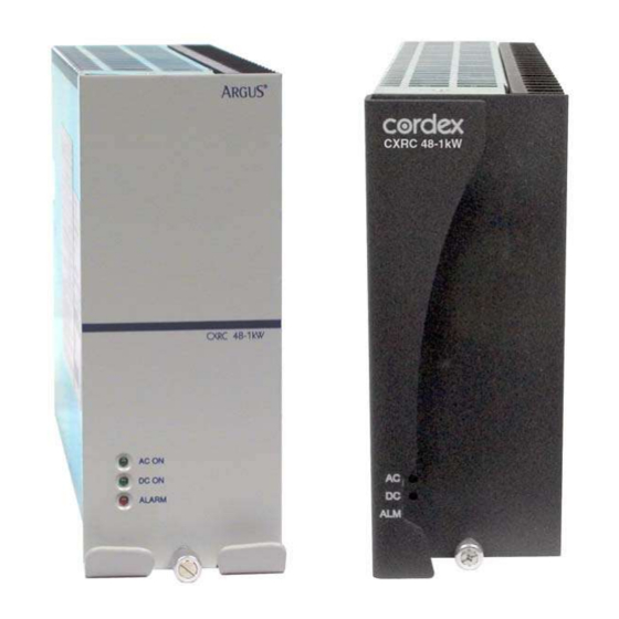
Rectifier Features Front Panel Figure 2–Cordex 48-1kW rectifier (gray and charcoal finishes shown) 2.1.1 LEDs The front panel LEDs provide: • Rectifier status summary, • Rectifier software upgrade in progress indication, • Locate module pattern. Rectifier status summary will show the rectifier alarm status, communication fail status and rectifier on/off status. 2.1.1.1 AC ON The top LED (green) is on when AC is within valid range. -
Page 18: Rear Panel
2.1.1.4 LED Activity During Software Upload When a rectifier software upload is in progress, the LEDs will behave in a distinctly different way to indicate new rectifier software is being transferred from the CXC. When a rectifier data transfer is in progress, all three LEDs will flash in a sequence lasting 1.5 seconds. -
Page 19: Wide Ac Range
Wide AC Range A minor alarm is generated when the AC input voltage drops below 180Vac. Output power is reduced linearly below 150Vac to 40% of the rated output power. At a lower voltage the module will shut down and will not restart until the AC is greater than or equal to 150Vac. -
Page 20: Cxcm Features
The CXCM (Cordex Controller, Modular) is mounted in the rectifier system shelf and brings advanced monitoring technology to the Cordex series of rectifiers. This compact 4RU system controller is designed for seamless operation and set up of Argus power systems and is equipped with the complete range of Cordex software features, including the following: •... -
Page 21: Analog Input Channels
3.1.2 LEDs The CXCM has three LEDs located on the front panel. These are used to display the alarm status of the power system, CXCM progress and status during startup, and file transfers. 3.1.2.1 Alarm Conditions The CXCM illuminates the LED that corresponds to the system alarm status. The following show the corresponding alarm status for each LED color: Green –... -
Page 22: Digital Input Channels
The communication protocol supports a web interface. All alarming and control of Cordex rectifiers is accomplished with a CXC via a CAN bus. A step-by-step connection wizard – provided to establish remote communications with your CXC – is available via the Argus website (www.argusdcpower.com). 030-713-C0 Rev A WC Page 8 of 23... -
Page 23: Inspection
Inspection Packing Materials All Argus products are shipped in rugged, double walled boxes and suspended via solid inserts to minimize shock that may occur during transportation. Packaging assemblies and methods are tested to International Safe Transit Association standards. Products are also packaged with Cortex. This plastic wrap contains a corrosive-inhibitor that protects the product from corrosion for up to two years. -
Page 24: Installation
Installation This chapter is provided for qualified personnel to install the product, which shall be mounted in a clean and dry environment. NOTE: To aid the user with installation, frequent reference is made to drawings located at the rear of the manual. Safety Precautions WARNING Hazardous voltages are present at the input of power systems. -
Page 25: Wiring And Connections
Wiring and Connections This chapter provides cabling details and notes on cable sizing for DC applications with respect to the Argus Cordex 48-1kW modular switched mode rectifier system. Refer also to drawing 030-713-08 at the rear of this manual. Safety Precautions WARNING Hazardous AC voltages may be present. -
Page 26: Calculating Output Wire Size Requirements
Calculating Output Wire Size Requirements Wire size is calculated by first determining the appropriate maximum voltage drop requirement. Using the formula below calculate the CMA wire size requirement. Determine the size and number of conductors required to satisfy the CMA requirement. CMA = (A x LF x K) / AVD, where: CMA = Cross section of wire in circular MIL area A = Ultimate drain in amps... -
Page 27: Can Serial Port
CAN Serial Port A single CAN Serial port (RJ-12 modular jack with offset latch) is provided for communications with Argus’ Cordex rectifiers and other CAN-enabled equipment. This is located on the shelf backplane. -
Page 28: Network Connection And Remote Communications Via Cxcm
Network Connection and Remote Communications via CXCM The Cordex system can be set up, monitored and tested via ETHERNET 10/100 Base-T serial data connection or with a RS-232 serial data connection. The communication protocol supports a web interface. NOTE: Pinouts are shown in customer connections drawing 030-713-08. Some standard scenarios are described below: 6.9.1 Ethernet Port for Network Connection (Standard Network Cable) -
Page 29: Alarm And Signal Wiring Connections For Cxcm
NOTE: To aid the user with installation, frequent reference is made to drawings located at the rear of this manual. Custom configurations may be detailed within the Argus power system documentation package. For terminal block connections, the recommended wire sizes are 0.823 to 0.129mm (#18 to #26 AWG) for the temperature range of 0 to 50 deg. - Page 30 (i.e. negative or positive) DC signal directly. 6.11.2.1 Connection Method Typical Argus systems use the “reset with Hot and trigger with Ground” connection. The digital input is wired in such a way that the Hot is wired directly into one of the input terminals; i.e., negative input for -48V systems.
- Page 31 Figure 8–Showing digital input connection method 6.11.2.2 Programming the Digital Input The digital input channels can be programmed for “active high” or “active low.” Active high indicates “alarm on the presence of a ground signal” and active low indicates “alarm on the removal of a ground signal.”...
-
Page 32: Operation
Operation Main Rectifier States Rectifier operation can be broken up into five main states: 1. Off, 2. Start delay, 3. Soft start, 4. Normal operation, 5. Turning off. Each state is characterized as being distinct and necessary for the operation of the rectifier. These states are briefly described below. -
Page 33: Main Rectifier Modes
Main Rectifier Modes In addition to Main Rectifier States, there is a set of Main Rectifier Modes. These modes can be divided into two categories as follows: 7.2.1 Output Voltage Modes Voltage modes can be thought of as modes that, under software control, can directly adjust the output voltage. The qualification of ‘under software control’... -
Page 34: Factory Ranges And Defaults
Factory Ranges and Defaults The following table lists the rectifier settings/ranges/defaults; changes are made via the CXC: Setting Range (minimum to maximum) Default Float Voltage 47.5 – 58.2V Equalize Voltage 49.8 – 60.2V Battery Test Voltage 44 – 52V See note below – 63V Current Limit 23 –... -
Page 35: System Startup
System Startup After completing the shelf wiring and installation, perform the following startup and test procedure to ensure proper operation: Check System Connections • Ensure AC is off, battery is disconnected • Ensure CXCM and all power modules are removed from the shelf. •... -
Page 36: Maintenance
Maintenance Although very little maintenance is required with Argus systems, routine checks and adjustments are recommended to ensure optimum system performance. Qualified service personnel should do repairs. The following table lists a few maintenance procedures for this system. These procedures should be performed at least once a year. -
Page 37: Argus Conventions
Outline Drawing “-20” Main Assembly Argus uses an eight-digit part numbering system for all components and sub assemblies. Each part is covered by its own unique number. Due to the quantity, categories will not be listed within this manual. 10.2... - Page 38 03071305B__.sch-1 - Mon May 14 15:17:29 2007...
- Page 39 03071305B__.sch-2 - Mon May 14 15:17:32 2007...
- Page 40 5.49 139.3 3.74 94.9 6.97 177.1 3.24 82.2 1.49 37.7 THESE DESIGNS AND SPECIFICATIONS ARE THE PROPERTY OF ARGUS TECHNOLOGIES AND SHALL NOT BE COPIED OR USED FOR MANUFACTURING WITHOUT ITS WRITTEN CONSENT. .875 K.O ACCEPTS 3/4" CONDUIT 2004/08 MATERIAL DESIGN...
- Page 41 JUMPER SETTING FOR P1 TB1 FEEDS RECTIFIER 3 THESE DESIGNS AND SPECIFICATIONS ARE THE PROPERTY OF TB2 FEEDS RECTIFIER 2 ARGUS TECHNOLOGIES AND SHALL NOT BE COPIED OR USED TB3 FEEDS RECTIFIER 1 FOR MANUFACTURING WITHOUT ITS WRITTEN CONSENT. DESIGN...
- Page 42 (707-340-20) TEMP 0 - 60V (SOME DETAILS OMITTED) THESE DESIGNS AND SPECIFICATIONS ARE THE PROPERTY OF GP1+ 1 ARGUS TECHNOLOGIES AND SHALL NOT BE COPIED OR USED FOR MANUFACTURING WITHOUT ITS WRITTEN CONSENT. SCALE TITLE CUSTOMER CONNECTION 3MDL,CXC,DIN DISTRN, 48-1KW...
- Page 43 6 POSITION LOAD CIRCUIT BREAKER BREAKERS HOT OUTPUTS THESE DESIGNS AND SPECIFICATIONS ARE THE PROPERTY OF ARGUS TECHNOLOGIES AND SHALL NOT BE COPIED OR USED FOR MANUFACTURING WITHOUT ITS WRITTEN CONSENT. REMOVE COVER FROM SCALE TITLE DIN RAIL DISTRIBUTION CUSTOMER CONNECTION...
- Page 44 This page intentionally left blank.
- Page 45 AOE will endeavor to repair products within five working days of receipt. Repairs to the returned product are warranted for a period of six months. A service charge may be applied if no fault is found in the returned product. Argus will not accept products without an SRO number.
- Page 46 Worldwide Corporate Offices Headquarter Germany France and Benelux Eastern Europe Russia fbnl@alpha-outback-energy.com russia@alpha-outback-energy.com ee@alpha-outback-energy.com Hansastrasse 8 D-91126 Schwabach Tel: +49 9122 79889 0 Middle East Spain Africa Fax: +49 9122 79889 21 me@alpha-outback-energy.com spain@alpha-outback-energy.com africa@alpha-outback-energy.com Mail: info@alpha-outback-energy.com Alpha and Outback Energy GmbH reserves the right to make changes to the products and information contained in this document without notice. Copyright © 2020 Alpha and Outback Energy GmbH. All Rights reserved.
Need help?
Do you have a question about the ALPHA OUTBACK ENERGY Cordex 48-1kW and is the answer not in the manual?
Questions and answers