Advertisement
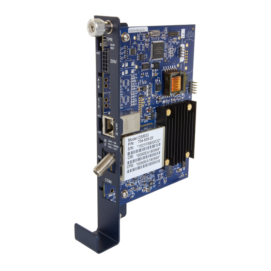
AlphaNet™ DM3.0 Series DOCSIS® Status Monitor
DM3.0 Series Transponder Installation for XM3 Quick Start Guide
Overview
CAUTION!
For XM3 units in service, backup battery power will not be available during this procedure.
DM3.0 Series Transponder installation and setup is comprised of three basic steps:
1. Installation of the DM3.0 Series transponder into the power supply, making front panel connections and verifying
operation.
2. Setting Options: The DM3.0 Series Transponders are designed for out-of-the-box, "plug and play" operation.
Non-default settings such as SNMP trap destination addresses may be required for the Network Management
System (NMS). SNMP trap addresses can be set automatically via the DOCSIS configuration file's
docsDevNmAccessTable per RFC 4639 (IPv4) or through the SNMPv3 Notification settings (IPv6), while DM3.0
Series proprietary options may be set through type 11 TLV entries. The SCTE-HMS MIBs may need to be
compiled into a MIB browser before it can be used to monitor or set transponder and power supply parameters.
Refer to the DM3.0 Series Technical Manual for details.
3. Configuring the Network: provisioning the DHCP Server with the transponder's MAC address and assigning it a
DOCSIS configuration file.
These steps can be performed independently of one another. However, configuring the network prior to field installation
will allow the installation to be verified while personnel are still on-site. Performing field installation before network
configuration might result in additional field service calls to correct mistakes.
Installation / Replacement Procedure
Before removing the Inverter Module, verify the power supply device address is correct.
The power supply device address must not be set to zero and no two power supplies monitored by a single DM3.0 Series
Transponder can have the same address. Power supplies must have 1, 2 ,3 ,4 or 5 as an address.
To verify the power supply's address, go to the LCD display on the inverter module and enter the "PWR CNFG" menu.
Scroll to the "Device Address" menu item and verify the device address is set to something other than 0 (Zero).
Removing the Inverter Module:
CAUTION!
Service personnel must verify the Inverter Module battery breaker remains in the OFF position
until instructed to return the unit to service.
1. Turn off the battery breaker.
2. Disconnect the battery input and temperature sensor cables from the Inverter Module, followed by the tamper, RF
and battery sense cables if a transponder is currently installed.
3. Loosen the thumbscrew on the XM3 Inverter Module and the thumbscrew on the transponder (if applicable).
4. Grasp the handle on the bottom right side of the Inverter Module. Pull firmly to release the module from the
inverter connector. Gently slide the module assembly straight out until the Inverter Module is accessible.
704-939-B1-001, Rev. A (09/2020)
1
Advertisement
Table of Contents

Subscribe to Our Youtube Channel
Summary of Contents for Alpha Outback Energy AlphaNet DM3.0 Series
- Page 1 AlphaNet™ DM3.0 Series DOCSIS® Status Monitor DM3.0 Series Transponder Installation for XM3 Quick Start Guide Overview CAUTION! For XM3 units in service, backup battery power will not be available during this procedure. DM3.0 Series Transponder installation and setup is comprised of three basic steps: 1.
- Page 2 5. If applicable, remove the old transponder from the inverter module. 6. Verify the Jumpers (J10 and J11) on the transponder are in the correct position for an XM3 installation (Fig. 1). 7. Set the notch at the back of the DM3.0 Series Transponder onto the white stand-off on the side of the Inverter Module (Fig.
- Page 3 9. Reinstall the Inverter Module, tighten the two thumbscrews and reconnect the front panel connections (tamper, temperature sensor, battery harness, etc.). 10. For the DM3X, connect the Battery Sense Wire Kit (not required with Smart AlphaGuard). Refer to the battery diagrams provided with the Sense Wire Kit or reference the DM3.0 Series Technical Manual (Alpha p/n 704-939- B0).
- Page 4 NOTICE: Using a DM3X in a system configuration with multiple power supplies or AlphaGen generator is optional. Generator (ECM) (Alpha p/n 744-726-XX) Communications Port Alpha Bus Cable ECM Interface (Alpha p/n 704-709-20) XM3 SI XM3 SI (Serial Interface) (Serial Interface) “Master”...
- Page 5 Initial Power-Up and Test / Returning the Unit to Service 1. Plug the power supply into the AC outlet. 2. Switch battery breaker ON. 3. The transponder LEDs will all blink in unison upon initial power up. The RDY LED will then begin blinking steadily indicating normal processor activity.
- Page 6 • Local Web Server Access: • You may also test the connection using a computer and a standard Ethernet cable. Connect the computer to the Ethernet port on the transponder, launch an Internet browser (e.g. Internet Explorer) and enter 192.168.100.1 in the address field. The General Configuration page shown below will appear and display connectivity, power levels and power supply status information such as alarms, output voltage, output current and individual battery voltages.
Need help?
Do you have a question about the AlphaNet DM3.0 Series and is the answer not in the manual?
Questions and answers