
Summary of Contents for BFGoodrich Stormscope WX-500
- Page 1 $12.00 U.S. $12.00 U.S. WX-500 WX-500 Stormscope Stormscope ® ® Series II Weather Mapping Sensor Series II Weather Mapping Sensor User’s Guide User’s Guide...
- Page 2 Stormscope line of weather mapping systems. The Stormscope system, the original, most accurate weather mapping system is manufactured by BFGoodrich Avionics Systems. Fly with Greater Confidence You now own the leading instrument in the world for airborne detection and mapping of thunderstorms.
- Page 3 BFGoodrich Avionics Systems, Inc. No government or other contractual support or relationship whatsoever has existed which in any way affects or mitigates proprietary rights of BFGoodrich Avionics Systems, Inc. in these developments. Methods and apparatus disclosed herein may be subject to U.S. Patents existing or applied for.
- Page 4 Important Notice All Stormscope ® WX-500 functions are controlled through various Multi-Function Displays (MFDs). The many capabilities of the WX-500 allow MFD manufacturers to create screens compatible with the various functions of their display. The display screens illustrated in this guide are intended to be characteristic of a group of MFDs that are configured to work with the WX-500.
-
Page 5: Table Of Contents
Table of Contents Page List of Illustrations ................iv List of Tables ..................iv Chapter 1 Description ..............1-1 General Description ..................... 1-1 Processor ......................1-1 Antenna ......................1-1 Functional Description ..................1-2 Cell Data ......................1-2 Strike Data ....................... 1-2 Strike Rate ...................... - Page 6 Discharge Points Off Aircraft’s Nose ............4-9 4-12 Line of Discharge Points While Taxiing ............ 4-10 4-13 Developing Cluster Within 25 nmi Range ..........4-10 List of Tables Table Title Page Error Messages ..................3-2 Stormscope WX-500 Specifications .............. 5-1 User’s Guide...
-
Page 7: Chapter 1 Description
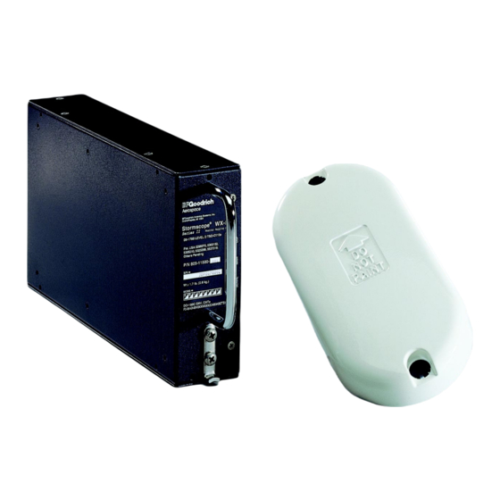
Chapter 1 Description GENERAL DESCRIPTION ® The Stormscope WX-500 Series II Weather Mapping Sensor detects electrical discharges associated with thunderstorms within a 200 nmi radius of the aircraft. This information is then sent to an external multifunction display (MFD) that plots the location of the associated thunderstorms. -
Page 8: Functional Description
® Description Stormscope WX-500 correlate the electric and magnetic signatures of lightning strikes better than other systems due to its patented sense channel technology. The antenna has been designed to help filter out pulsed noise from sources other than atmospheric electrical discharges. Electromagnetic Signals Radiating from Atmospheric Electrical Discharges Associated with Thunderstorms... -
Page 9: Strike Rate
® Stormscope WX-500 Description Strike Rate The estimated strike rate may be used by pilots to determine if storm cells are building or decaying. The strike rate is calculated by the MFD for the current range and view. It represents the approximate strikes-per-minute. FEATURES •... -
Page 10: Chapter 2 Storm Mapping Principles
Chapter 2 Storm Mapping Principles ANATOMY OF A THUNDERSTORM The Stormscope model WX-500 is intended to help pilots avoid the dangers associated with thunderstorms (convective wind shear, lightning, icing, tornadoes, etc.). The WX-500 locates thunderstorms by detecting the electrical discharges that thunderstorms always generate. -
Page 11: Stages Of A Thunderstorm
® Storm Mapping Principles Stormscope WX-500 Figure 2-2 shows that the rate of electrical discharges detected in an area is directly related to the amount of convective wind shear turbulence present. In fact, as convective wind shear increases, the rate of electrical discharges increases at an increasing rate. This relationship means that if you find the electrical discharges, you’ve found the wind shear. -
Page 12: The Wx-500 And Weather Radar
® Stormscope WX-500 Storm Mapping Principles THE WX-500 AND WEATHER RADAR The storm mapping technology used in the WX-500 is fundamentally different than the technology used in weather radar. Weather radar operates by transmitting UHF radio waves in the direction of interest and then receiving echoes from water droplets, whereas the WX-500 operates by receiving signals already present in the atmosphere due to electrical discharges. -
Page 13: Chapter 3 Operation
Chapter 3 Operation INTRODUCTION As mentioned earlier, WX-500 functions are controlled through the MFD. For detailed operating instructions refer to your aircraft Flight Manual Supplement and the documen- tation supplied with the MFD. The focus of this chapter is to provide supplemental information, which may be background information or a more detailed explanation of a particular operational feature. -
Page 14: Error Messages
® Operation Stormscope WX-500 ERROR MESSAGES The WX-500 detects most common faults and sends error messages to the MFD indicating the nature of the faults and which functions may be inoperative. These error messages enable your authorized Stormscope dealer or BFG Avionics Systems factory service personnel to quickly diagnose and correct the fault. - Page 15 ® Stormscope WX-500 Operation Table 3-1. Error Messages (Continued) Error Fault Source Type* Recommended Action was applied to returns. If not correctable, the system continue without weather mapping functions and see your dealer for service. Error 21 Main processor Turn off the unit and see your Processor Fault dealer for service.
-
Page 16: Nonfatal Faults
® Operation Stormscope WX-500 Table 3-1. Error Messages (Continued) Error Fault Source Type* Recommended Action Error 52 NF/R See your dealer for service if Invalid Antenna this error occurs frequently. Change Request Error 53 thru 54 NF/R See your dealer for service if Communications this error occurs frequently. -
Page 17: Chapter 4 Weather Display Interpretation
Chapter 4 Weather Display Interpretation Never use your Stormscope system to attempt to penetrate a thunder- storm. The FAA Advisory Circular, Subject: Thunderstorms, and the Airman’s Information Manual (AIM) recommend that a pilot “avoid by at least 20 miles any thunderstorm identified as severe or giving an intense radar echo.”... -
Page 18: Radial Spread
WX-500. These phenomena are examples of radial spread. Discharge points in radial spread do not necessarily indicate the exact location of atmospheric electrical discharges. To counteract radial spread, BFGoodrich Avionics Systems applied its extensive research in lightning detection to develop enhanced lightning positioning algorithms. These algorithms (used only in the cell display mode) greatly reduce radial spread and improve the depiction of thunderstorms on the display. -
Page 19: Three Clusters Within 200 Nmi
® Stormscope WX-500 Weather Display Interpretation Rate Rate CELL STRIKE 200nm 200nm Figure 4-2. Three Clusters Within 200 nmi Rate Rate CELL STRIKE 100nm 100nm Figure 4-3. Range Changed to 100 nmi User’s Guide... -
Page 20: Two Clusters Within The 200 Nmi Range
® Weather Display Interpretation Stormscope WX-500 Two Clusters within the 200 nmi Range Figure 4-4 illustrates the 360° weather view at the 200 nmi range. Using this knowledge, the two clusters of discharge points on the screen can be interpreted as representing one thunderstorm cell at 5:30, about 150 nmi from the aircraft, and another thunderstorm cell at 1 o’clock, about 100 nmi from the aircraft. -
Page 21: Range Set At 200 Nmi
® Stormscope WX-500 Weather Display Interpretation Rate 117 Rate 125 CELL STRIKE 200nm 200nm Figure 4-5. Range Set at 200 nmi Rate 118 Rate 127 CELL STRIKE 200nm 200nm Figure 4-6. Aircraft Progresses 100 nmi User’s Guide... -
Page 22: Range Changes To 100 Nmi
® Weather Display Interpretation Stormscope WX-500 Range Changes to 100 nmi Figure 4-7 shows the screen a short time later in the 120° weather view at the 100 nmi range. The thunderstorms at 8:30 are not visible in this view but the thunderstorms off the nose of the aircraft appear in greater detail as two separate thunderstorms. -
Page 23: Range Changes To 100 Nmi
® Stormscope WX-500 Weather Display Interpretation Rate Rate CELL STRIKE 100nm 100nm Figure 4-7. Range Changes to 100 nmi Rate Rate CELL STRIKE 100nm 100nm Figure 4-8. Aircraft Turns To Avoid Thunderstorms User’s Guide... -
Page 24: Randomly Scattered Discharge Points
® Weather Display Interpretation Stormscope WX-500 Rate Rate CELL STRIKE 200nm 200nm Figure 4-9. Randomly Scattered Discharge Points Rate Rate CELL STRIKE 25nm 25nm Figure 4-10. Cluster and Splattering Within 25 nmi User’s Guide... -
Page 25: Discharge Points Off Aircraft's Nose
® Stormscope WX-500 Weather Display Interpretation Discharge Points Off Aircraft’s Nose Figure 4-11 illustrates the 360° weather view at the 200 nmi range. The discharge points ahead of the aircraft could be caused by a strong thunderstorm just beyond the 200 nmi range. -
Page 26: Line Of Discharge Points While Taxiing
® Weather Display Interpretation Stormscope WX-500 Rate Rate CELL STRIKE 200nm 200nm Figure 4-12. Line of Discharge Points While Taxiing Rate Rate CELL STRIKE 50nm 50nm Figure 4-13. Developing Cluster Within 25 nmi Range 4-10 User’s Guide... -
Page 27: Chapter 5 Specifications
Chapter 5 Specifications Table 5-1. Stormscope WX-500 Specifications Part Number: 805-11500-001 Features: Cell or Strike mode 200 nmi range Built-in self tests Automatic heading stabilization Microphone inhibit line Integrity indicator Dimensions: Processor (includes mounting tray and pull handle): 5.6 inches (14.22 centimeters) high 2.2 inches (5.59 centimeters) wide... -
Page 28: Chapter 6 Warranty Information
Chapter 6 Warranty Information INTRODUCTION The Stormscope WX-500 sensor is warranted for 2 years from the date of installation (not to exceed 30 months from the date of shipment from BFGoodrich Avionics Systems) subject to the following limitations. WARRANTY STATEMENT... -
Page 29: Related Policies And Procedures
WX-500 is installed during the warrant y period, the remaining warrant y may be transferred. Written notification of the transaction must be submitted by the initial recipient of the warranty to: ATTENTION: WARRANTY ADMINISTRATOR BFGoodrich Avionics Systems 5353 52nd Street, S.E. Grand Rapids, MI 49588-0873 U.S.A. - Page 30 Serial Number _______________________________________________ Note To ensure that a repaired meets the , gets for- Stormscope FAA TSO eign government approval, and meets BFGoodrich Avionics Sys- tems, Inc. performance standards, your must be reinstalled WX-500 and tested by a -authorized dealer.
- Page 31 009-11501-001 (Rev. A, 9/10/97) BFGoodrich Avionics Systems, Inc. Stormscope ® 5353 52nd Street, S.E. P.O. Box 873 Series II Weather Mapping Systems Grand Rapids, MI 49588-0873 USA...
Need help?
Do you have a question about the Stormscope WX-500 and is the answer not in the manual?
Questions and answers