Table of Contents
Advertisement
Advertisement
Table of Contents
Troubleshooting

Related Manuals for Laser Key Products 3D Pro Xtreme

Summary of Contents for Laser Key Products 3D Pro Xtreme
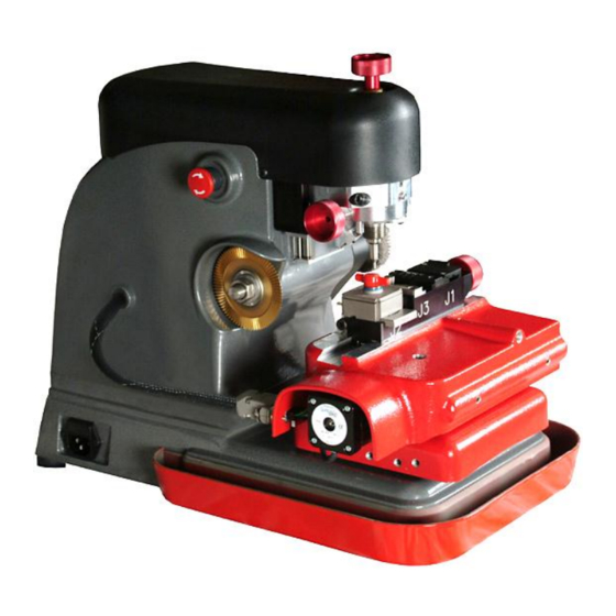
- Page 1 3D Pro User Guide The 3-D Pro will only operate as instructed on clean power. Please make sure that the correct cutter and jaw combination are in place before cutting the key!!!! It is recommended that Safety Glasses be worn at all times when operating this machine.
-
Page 2: Table Of Contents
SOFTWARE INSTALLATION SOFTWARE ACTIVATION DRIVER INSTALLATION DRIVER CONFIGURATION CHANGING THE CUTTER AND CALIBRATION STYLUS CHANGING TRACER CALIBRATING THE 3D PRO XTREME USING JAW 1 USING JAW 3 USING JAW 2 USING THE STANDARD TRACING ADAPTER TROUBLESHOOTING THE STANDARD TRACING ADAPTER... -
Page 3: Checking Your New 3D Pro Upon Arrival
Optional Parts: Bolt-Down Kit - Laptop Mount - Tibbe Adapter – Tubular Jaw Newer 3D Pro Xtreme key machines have a hard wired motor control cable but on older machines the 9 pin serial cable exiting the left side of the machine case should only be plugged into the 9 pin serial plug on the left side of the X table. -
Page 4: The Emergency Stop (On/Off) Button
Page 3 of 55 The Emergency Stop (On/Off) Button The Emergency Stop acts as the On/Off Switch. The “Emergency Stop Button” is situated on the left hand side of the machine. In an emergency, hit the button to turn off the machine. -
Page 5: Software Activation
Page 4 of 55 Software Activation After installation, Double-click your new desktop icon and the License Configuration appears. (Some downloaded versions will only ask to activate after 3 runs. This is because we allow users to trial the software and also to let users operate the machine in case they can’t get an activation code quickly such as if the software is installed after hours.) 1. -
Page 6: Driver Installation
“Device Manager” and look for “Other Devices > Motion Controller” Right Click “Motion Controller” and Click “Update Driver” Choose install from specific location and Browse to “c:\ laser key products\3d pro windows drivers” and click next then finish. If an unsigned driver warning appears then select “Continue Anyway”... -
Page 7: Driver Configuration
Page 6 of 55 Driver Configuration After installing the 3D Pro software and drivers, follow these steps to get the machine communicating with the computer. These steps can also be used if you get a “Motion board not connected” Error. 1. - Page 8 Task Manager (Control Alt Delete on your keyboard and then clicking start Task Manager.) Select any items labeled “3D Pro Xtreme.exe” and then click “End Process” 5. Unplug the USB Cable for 15 seconds, plug it back in and wait 15 more seconds and then start the software for the machine.
-
Page 9: Changing The Cutter And Calibration Stylus
Page 8 of 55 If you still get error connecting then right click the desktop icon for the 3D Pro, click Properties and then click the compatibility tab, set the settings shown below and press ok. Try to start the software again. Changing the Cutter and Calibration Stylus “The Collet”... -
Page 10: Changing Tracer
Page 9 of 55 does not have to be extremely tight, hand tight should be sufficient. If one of the ends of your TR62.2 double ended Jaw 2 cutter is broken, you will notice that it inserts further into the collet than normal. - Page 11 Page 10 of 55 Double Ended tracer tip installation: When installing a double ended tracer, tighten the set screw that holds the tracer tip in place in between the two dimples. The tracing function for duplicating keys works only on metal; don’t try to duplicate plastic keys.
-
Page 12: Calibrating The 3D Pro Xtreme
Page 11 of 55 Calibrating the 3D Pro Xtreme If you get “Obstruction Detected” errors you may need to calibrate, make sure you are calibrating with the stylus and not the cutter when calibrating. Calibrating Cutter for Jaw 1: 1. Clean any shavings or debris from jaw (Any metal shavings, dirt or grease that the stylus touches will take an incorrect reading). - Page 13 Page 12 of 55 Calibrating Tracer for Jaw 1: 1. Always have a “Cutter” or “Stylus” installed while calibrating the Tracer, do not leave the collet empty or it will get in the way of the Tracer. 2. Flip the tracer arm down with the “red knurl knob” on the left side of the head.
- Page 14 Page 13 of 55 Calibrating Cutter for Jaw 2: 1. Clean any shavings or debris from jaw (Any metal shavings, dirt or grease that the cutter touches will take an incorrect reading) 2. Close the Jaw 2 so that it is completely shut with the ‘A’...
- Page 15 Page 14 of 55 There is no tracing for Jaw 2 Calibrating Cutter for Jaw 3: 1. Clean any shavings or debris from jaw (Any metal shavings, dirt or grease that the stylus touches will take an incorrect reading). And open Jaw all the way! 2.
- Page 16 Page 15 of 55 Calibrating Tracer for Jaw 3: 1. Never have a “Cutter” or “Stylus” installed while calibrating the Tracer, leave the collet empty or it will get in the way of the Tracer and cause an error. 2. Flip the tracer arm down with the “red knurl knob”...
-
Page 17: Using Jaw 1
Page 16 of 55 USING JAW 1 The Cutter used most with Jaw1 is always “Jaw1” is always used for ALL high security This is the the TR2.5 single ended (laser style keys) except Volkswagen (VW) “Jaw 1 Tip Stop” Cutter: Clamping High Security Keys in Jaw 1 Using the “Tip Stop”... - Page 18 Page 17 of 55 Jaw 1 Tipstop Example: Using the Jaw 1 “Shoulder Stop” When selecting keys that calls for a “Shoulder” stop, place the key in the jaw and slide it forward until the shoulder of the key is touching the front of the jaw.
-
Page 19: Using Jaw 2
Page 18 of 55 Using Jaw 3 (Jaw 3) When a VAG (HU66) key is selected, it requires Jaw 3 to be used. Insert the key into Jaw 3 and slide the key forward until the shoulder of the key and tighten the red knob on the right of Jaw 1. USING JAW 2 When loosening the Jaw 2 clamp be careful not to unscrew the red T knob too far, doing will cause the moving Jaw 2 top to slide out of the fixed Jaw 2 inner base and will require special... - Page 20 Page 19 of 55 Clamping Non-High Security “Shoulder Stop” Keys in Jaw 2 When you select a standard security key from the menu, the software will tell you which “Stop” to use, “Shoulder” or “Tip” This is an example of a Shoulder Stop key. Slide the key forward until it stops on the shoulder of the key.
- Page 21 Page 20 of 55 Circled in is the milling of this Y157 Key. It is the thinest part of the key along the edge. Sometimes, depending on the blank used, the key will try to twist out of the jaw or otherwise not clamp properly. A shim can be used to hold the key tight as illustrated.
-
Page 22: Using The Standard Tracing Adapter
Page 21 of 55 Using the Standard Tracing Adapter The Standard Tracing Adapter holds standard security keys in Jaw 1 for tracing with the high security tracer. Once the key is traced the cuts are filled in and a standard key can then be cut using Jaw 2. Slide the lip on the bottom of the Standard Tracing Adapter up to the front of the Jaw 1 and clamp the adapter flat into Jaw 1 where a high security key would clamp. - Page 23 Page 22 of 55 Clamping Tip Stop Keys Clamp tip stop keys so that they don’t go past the lip that the keys clamp on. Clamp on milling when possible. Leave tipstop down touching the tip of the key when tracing tipstop keys. Correct Clamping: Incorrect Clamping: Initiating a trace from the software...
-
Page 24: Troubleshooting The Standard Tracing Adapter
Page 23 of 55 Troubleshooting the Standard Tracing Adapter If you are having trouble working with the Standard Tracing Adapter then check to make sure the software is setup properly. With the machine powered on and connected and go to File > Setup at the top left of the main software screen. -
Page 25: Tubular Jaw
Page 24 of 55 If you are getting consistently wrong readings when using the Standard Tracing Adapter you may have to adjust the tracer angle, a video of the procedure can be found in the 3D Xtreme help section at LASERKEYPRODUCTS.COM. Also, it is important that the Standard Tracing Adapter be completely flat on Jaw 1. - Page 26 Page 25 of 55 The Tubular tracer can be used to trace all keys, it is not necessary change out the tracer when changing jaws. If you alternate between tracers you will have to calibrate each time You will have to calibrate the new tracer for Jaw 3 also unless you plan to alternate between tracer types then you only have to calibrate for Jaw 1 Using the Tubular Jaw Loosen the red t-knob behind the main jaw assembly, slide off the main jaw assembly, and...
- Page 27 Page 26 of 55 Then select the key blank being used. After placing the tubular key in the tubular jaw then click ‘Trace’ or enter cuts using the keyboard and click ‘Start’ when ready to cut. Tubular Key DSDs 405, 406, 410, 411, 412, 413, 414, 415, 416 To search by DSD click ‘Search’...
-
Page 28: Tibbe Key And Tibbe Adaptor
Page 27 of 55 Tibbe Key and Tibbe Adaptor This enables us to insert the key blank into the adaptor “sideways” and rotate 90° into place. Cutting a FORD “Tibbe” Key - Silca FO21 (DSD 358) - Page 29 Page 28 of 55 On the main screen you will see three tabs “Automotive” “Type/Manufacturer” and “Search” Click on “Commercial/ Domestic” and choose “Ford” from the drop down menu. Now click on “FO21” (DSD 358) to open up the “Main cutting screen”...
- Page 30 Page 29 of 55 Cutting a JAGUAR “Tibbe” Key - Silca TBE1 (DSD 356) Inserting the Jaguar Tibbe Key into the “Tibbe Adaptor” is exactly the same as inserting the Ford Tibbe Key and choose the Jaguar from the “Type/Manufacturer” tab. Click on “Commercial/ Domestic”...
-
Page 31: Selecting Keys In The Software
Page 30 of 55 Selecting keys in the software There are three ways to select keys in the 3D Pro software, if you can’t find a key one way then try another. If you try to select a key from the year make and model selector only to find the year you have is not listed then try the closest year or make of vehicle or select the... -
Page 32: Saving And Loading Customer Keys Database
Key Products” folder on computer running the machine. This file must be backed up periodically to prevent data loss. Backing up the Customer Keys Database: Go to the “C:\Laser Key Products” folder and copy the “Customers.mdb” to a USB Drive or Online Backup. Restoring the Customer Keys Database: Copy the backed up “Customers.mdb”... - Page 33 Page 32 of 55 Saving Keys: Select a key as normal and fill in the cuts by using a code, tracing a key, or entering the cuts manually. Then click File and Save Key. Enter the available customer data into “Step 1:”...
- Page 34 Page 33 of 55 Next, on the right side on the customer keys window click the “Add” then “Done” buttons to add the key to the selected customer. Loading customers and their keys: To load a previously saved key click “File” and “Load Key”...
- Page 35 Page 34 of 55 Type a search term into any of the customer data fields and click the “Search” button. All fields are searchable including the generated ID. Click the requested customer from the search results box at the bottom of the customer information box.
-
Page 36: Space And Depth Adjustments
Page 35 of 55 SPACE AND DEPTH ADJUSTMENTS The following pages will show you how to check and set your machine to cut and trace perfectly. Explaining the X, Y, Z Axis for Jaw 1 and Jaw 3 1. Jaw 1 uses three axes which are X, Y, and Z 2. - Page 37 Page 36 of 55 Adjusting Space and Depth on Jaw 1 and Jaw 3 High security keys that are cut and traced on Jaws 1 and 3 uses a profile that can be shifted along the space and depth. We will use a High Security Honda key as an example of how to adjust Jaw 1. In the 3D Pro software with this Honda key selected go to: ‘File >...
- Page 38 Page 37 of 55 To measure the spacing on a tip stop key like the To measure a depth high security on a high security Honda key set a Honda key, find the caliper to the space for the depth space that you you want to want to measure...
- Page 39 Page 38 of 55 To make this adjustment go to “Operations > Space and Depth Adjustment” type “1” and press “OK” You will see the window shown above. Type “3” under “Tracer” next to “Depth Offset:” and then press “Update” Adjusting space and depth for the Jaw 1 cutting is the same as adjusting Jaw 1 Tracer accept that you will have to cut a key, measure it, and make the adjustment.
- Page 40 Page 39 of 55 You will see the window shown above. Type “-3” under “Cutter” next to “Depth Offset:” and then press “Update”. Repeat the same process for spacing. Adjusting Space and Depth on Jaw 2 We will use a Schlage key as an example of how to adjust Jaw 2. In the 3D Pro software with this Schlage key selected go to: ‘File >...
- Page 41 Page 40 of 55 To measure a To measure the depth on a spacing on a Schlage key, shoulder stop key find the space like the Schlage for the depth key, set a caliper to you want to the space that you measure and want to measure measure from...
- Page 42 Page 41 of 55 To adjust the spacing, cut a Schlage key to all ones with a 3 in the third space set your calipers to .543 inches and measure from the shoulder to the tip and see if the 3 cut meets the measurement.
-
Page 43: Explaining The Software: Buttons And Menus
Page 42 of 55 Explaining the software: Buttons and Menus Half Cut The button “Half Cut” refers to cutting 1/2 depths when using Determinators. When half cut mode is entered, 1=1-1/2 (one and a half) and 3=3-1/2 (three and a half) etc. You must still follow the procedures to choose the correct key blank type first. - Page 44 Page 43 of 55 Key Blank Tells you what key blank you should be using. Manufacturer The manufacturer gives you reference to the current car you are working on. Spaces This value tells you how many spaces are on the key you are working with.
- Page 45 Page 44 of 55 Stop There are 4 different types of “Stop”: Shoulder, Tip 1, Tip 2, and Tip 3. Make sure that you insert the key to the correct tip stop. If not done properly, you may cut the key wrong or damage the cutter. Comment Boxes There are two comment boxes.
-
Page 46: Key Editor
Page 45 of 55 Re-Connect The re-connect button is only used when the board cannot be found. To use this button you must cycle the power on the machine off and then on again. You may now press the reconnect button to refresh it with the software. - Page 47 Page 46 of 55 Click “Yes” to the authorized user warning and Choose “This Computer” as the user name, leave the password blank and press OK. Center Distance: Controls where the center of a high security internal cut key is located from the left edge of the Jaw 1 clamp in thousandths of an inch.
- Page 48 Page 47 of 55 To widen the angles, increase the angle number. To narrow the angles, decrease the angle number. After editing click the Done button at the bottom left of the software to save changes. Half Cut Depth This is for use with Determinators. When clicking on the “Half Cut” button on the main screen, it will flash red to indicate that it has been selected.
-
Page 49: Troubleshooting
Open Task Manager by pressing Control Alt Delete on your keyboard and then clicking Task Manager. Look for ‘3D Pro Xtreme.exe’, click it, then click “End Process” Then start the 3D Pro software again. - Page 50 Page 49 of 55...
-
Page 51: Using An Inverter
If a problem occurs that you are unable to repair yourself, please seek the assistance of a qualified vehicle electrician. If you plan to use an inverter to power your 3D Pro Xtreme key machine, it is recommended that you use only a PURE SINE WAVE INVERTER with a CONTINUOUS output rating of at least 1500 - 2000 watts. - Page 52 Page 51 of 55 • Properly grounding your inverter to the vehicle CHASSIS is absolutely essential for trouble free operation. • Shorter and fatter is better! Keep your wiring and cabling as short as reasonably possible. When selecting wire and cable gauges, err on the side of larger diameter rather than smaller.
-
Page 53: Example Of Inverter Chassis Grounding
Page 52 of 55 Example of Inverter Chassis Grounding... -
Page 54: Changing The Fuses
Page 53 of 55 Changing the Fuses !!Please Disconnect Machine Before Proceeding to Change Fuses!! Insert a small tipped screwdriver into slotted area in the front face of the fuse box located on the left side of the 3D Pro key machine and pull fuse cartridge toward you. -
Page 55: Optional Accessories
Page 54 of 55 Optional Accessories Bolt Down Kit Lexus 80000 Code Series Cutter Tibbe Adapter Preloaded Laptop Genericode for 3D Pro Laptop Mount Tubular Jaw Tubular Cutter Standard Tracing Adapter LaserKeyProducts.com...
Need help?
Do you have a question about the 3D Pro Xtreme and is the answer not in the manual?
Questions and answers