Table of Contents
Advertisement
Quick Links
Advertisement
Table of Contents

Related Manuals for Lauda MID 80

Summary of Contents for Lauda MID 80
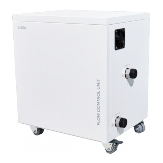
- Page 1 Operation manual Flow controller MID 80 for LAUDA Integral process thermostats IN 150 XT, IN 250 XTW, IN 280 XT(W), IN 550 XT(W), IN 590 XTW, IN 750 XT, IN 950 XTW, IN 1590 XTW, IN 1850 XTW, IN 2560 XTW, IN 2050 PW, IN 2560 PW, IN 4 XTW, IN 8 XTW...
- Page 2 Manufacturer LAUDA DR. R. WOBSER GMBH & CO. KG Pfarrstraße 41/43 97922 Lauda-Königshofen Deutschland Telephone: +49 (0)9343 503-0 Fax: +49 (0)9343 503-222 E-mail: info@lauda.de Internet: https://www.lauda.de Q5WT-QA13-005, 2, en_US 08/10/2021 © LAUDA 2021 replaces issue V1R33, catalog number L003217 2 / 38...
-
Page 3: Table Of Contents
Maintenance..................................26 Warning notes on maintenance and repair......................26 Maintenance intervals..............................26 Faults..................................... 27 Decommissioning................................28 Disposal....................................29 Disposing of packaging............................... 29 Disposing of heat transfer liquid..........................29 Disposing of an old device............................29 Flow controller MID 80 3 / 38... - Page 4 General....................................30 10.1 Copyright..................................30 10.2 Technical changes............................... 30 10.3 Warranty conditions..............................30 10.4 Contact LAUDA................................ 30 Technical data..................................31 Declaration of Incorporation.............................. 34 Product Returns and Clearance Declaration........................36 Index..................................... 37 4 / 38 Flow controller MID 80...
-
Page 5: Safety
Always check the device, the LiBus cable and the hoses for damage and leaks before operation. Any defects found must be remedied in line with good professional practice before operation. Never operate the device without heat transfer liquid. Flow controller MID 80 5 / 38... -
Page 6: Intended Use
The device may only be operated as intended and under the conditions specified in this manual. Any other type of operation is considered improper and may impair the protection supported by the device. LAUDA accepts no liability for damage resulting from improper use of the device. -
Page 7: Environmental Limits
Heat transfer liquids are used to control the temperature. LAUDA heat transfer liquids are recommended for the flow controller. LAUDA heat transfer liquids have been tested by the company LAUDA DR. R. WOBSER GMBH & CO. KG and approved for the flow controller. -
Page 8: Materials Used
Service work may only be performed by the LAUDA Service department or a service partner authorized by LAUDA. 8 / 38 Flow controller MID 80... -
Page 9: Structure Of Warnings
Consequences of not following instructions Measure 1 Measure... Notice A "notice" warns that dangers to property or the environment may exist. NOTICE! Type and source Consequences of not following instructions Measure 1 Measure... Flow controller MID 80 9 / 38... -
Page 10: Unpacking
Also notify the LAUDA Service depart- ment immediately. You will find the contact information here Ä Chapter 10.4 “Contact LAUDA” on page 30. -
Page 11: Scope Of Delivery
Flow controller MID 80 L003217 Plastic screw cap EZV 194 Operating manual Q5WT-QA13-005 * Please complete the warranty card and return it to LAUDA. Accessories The following accessories are recommended for connecting the device: Table 3 Quantity Article Order No. -
Page 12: Device Description
XT devices or a maximum of 140 °C on P devices. The flow controller has an internal bypass. The electronically controlled bypass is used to adjust and regulate the flow rate. Fig. 2: Hydraulic diagram MID 80 Constant temperature equipment Application... -
Page 13: Structure
Device is connected to the constant tem- perature equipment via the LiBus interface Power consumption Maximum power consumption of the device Fig. 5: Rating label of the MID 80 during operation (example) Protection class IP protection level of the device... -
Page 14: Before Starting Up
Connect the hoses and LiBus cable CAUTION! Bursting of the hose and leaking of heat transfer liquid. Scalding, frostbite, slipping hazard The temperature, pressure and media resistance of the hoses must be suitable for the respective application. 14 / 38 Flow controller MID 80... - Page 15 Refer to the operating manual of the constant temperature equip- ment for the permissible torque of the union nuts. All hydraulic connections on the flow controller have an external thread M38 x 1.5 mm. Flow controller MID 80 15 / 38...
- Page 16 Secure the connection by turning the ring on the connector clockwise. If a free LiBus interface is not available on the constant temperature equipment: Use a T-extender adapter cable (EKS 073). 16 / 38 Flow controller MID 80...
- Page 17 Read the operating manual of the constant temperature equipment for instructions. The properties of the heat transfer liquid used can be found in this oper- ating manual and in the operating manual of the constant temperature equipment. Flow controller MID 80 17 / 38...
-
Page 18: Commissioning
If degassing is necessary, carefully degas the entire circuit. Top up the constant temperature equipment with the same heat transfer liquid, if required. Always check the condition of the system before switching it on. 18 / 38 Flow controller MID 80... - Page 19 The pressure indication of the pump on the Integral IN display switches to the measured pressure level in MID 80. In the basic window of the constant temperature equipment, the pressure of the heat transfer liquid at the outlet of the flow controller is displayed in the direction of the application.
- Page 20 22). If the pressure limitation is still active, the system will regulate the pressure to the set pressure level. on - The flow controller regulates to the flow rate set in the Setpoint menu. 20 / 38 Flow controller MID 80...
- Page 21 Switch off the constant temperature equipment at the mains switch. This also switches off the flow controller. Disconnect the constant temperature equipment from the power supply (mains plug) before carrying out any further installation or maintenance work. Flow controller MID 80 21 / 38...
-
Page 22: Operation
The maximum pressure value must be lower than the bursting pres- sure of the connected application. If the set maximum pressure is reached during operation, the constant temperature equipment switches off and signals the overpressure alarm. 22 / 38 Flow controller MID 80... -
Page 23: Setting The Control Parameters
The control parameters should only be configured by quali- fied personnel. A continuous valve and the pump power (on Integral XT) are used as actuating signals for through-flow control. You can parameterize both actuating signals via separate PI controllers. Flow controller MID 80 23 / 38... -
Page 24: Draining The Device
Draining the flow controller is required, e.g. to change or replace the heat transfer liquid. The device must also be completely drained before transport or disposal. There is approximately 1 liter of heat transfer liquid in the device. 24 / 38 Flow controller MID 80... - Page 25 Select the menu items Fill mode Drain and confirm with the Enter key. The options [off] and [on] appear on the display. Select the option [off] and confirm the entry. The draining of the flow controller has been completed. Flow controller MID 80 25 / 38...
-
Page 26: Maintenance
Durchflussregler. Remedy any defects found immediately, at the latest before the next operation. In the case of major damage, contact the manufacturer immediately Ä Chapter 10.4 “Contact LAUDA” on page 30. 26 / 38 Flow controller MID 80... -
Page 27: Faults
Motor of the control valve defective Flow meter calibration The internal flow meter can be calibrated on site, if required. To do so, contact LAUDA Service Ä Chapter 10.4 “Contact LAUDA” on page 30. Flow controller MID 80 27 / 38... -
Page 28: Decommissioning
Hold back the con- necting sleeve with a second open-end wrench when unscrewing the union nut. Screw the screw caps onto the four connection sleeves by hand to protect the inside of the device from contamination. 28 / 38 Flow controller MID 80... -
Page 29: Disposal
Dispose of the device in accordance with the applicable disposal guide- lines in your region. Comply with Directive 2012/19/EU (WEEE Waste of Electrical and Electronic Equipment) if disposing of the product takes place in a member state of the EU. Flow controller MID 80 29 / 38... -
Page 30: General
Warranty conditions LAUDA grants a standard warranty of one year. 10.4 Contact LAUDA Contact the LAUDA Service department in the following cases: Troubleshooting Technical questions Ordering accessories and spare parts Please contact our sales department for questions relating to your specific application. -
Page 31: Technical Data
Thread on the hydraulic connections (exterior thread) mm M38 x 1.5 Thread on the drain nozzle (exterior thread) G 3/8" A Filling volume Dimensions (width x depth x height) 605 x 420 x 620 Flow controller MID 80 31 / 38... - Page 32 As a general rule: The lower the flow rate, the higher the control accuracy. The lower the temperature, the higher the control accu- racy. 32 / 38 Flow controller MID 80...
- Page 33 Fig. 18: Characteristics with an outflow temperature of 20 °C (measured with Kryo 30, without counter-pressure) Fig. 19: Characteristics with a flow rate of 10 l/min (measured with Kryo 30, without counter-pressure) Flow controller MID 80 33 / 38...
-
Page 34: Declaration Of Incorporation
Declaration of Incorporation 34 / 38 Flow controller MID 80... - Page 35 EC DECLARATION OF INCORPORATION Manufacturer: LAUDA DR. R. WOBSER GMBH & CO. KG Pfarrstrasse 41/43 97922 Lauda-Königshofen Germany We hereby declare under our sole responsibility that the machines described below Product Line: MID 80 Serial number: from S210000001 comply with all relevant provisions of the EC Directives listed below due to their design and type of construction in...
-
Page 36: Product Returns And Clearance Declaration
Product Returns and Clearance Declaration Product Returns Would you like to return a LAUDA product you have purchased to LAUDA? For the return of goods, e.g. for repair or due to a complaint, you will need the approval of LAUDA in the form of a Return Material Authorization (RMA) or processing number. -
Page 37: Index
Warning ....... . . 27 Flow controller MID 80 37 / 38... - Page 38 Warranty ....... . 30 38 / 38 Flow controller MID 80...
- Page 40 Manufacturer LAUDA DR. R. WOBSER GMBH & CO. KG ◦ Pfarrstraße 41/43 ◦ 97922 Lauda-Königshofen Telephone: +49 (0)9343 503-0 ◦ Fax: +49 (0)9343 503-222 E-mail: info@lauda.de ◦ Internet: https://www.lauda.de...
Need help?
Do you have a question about the MID 80 and is the answer not in the manual?
Questions and answers