Table of Contents
Advertisement
Quick Links
Advertisement
Table of Contents

Summary of Contents for Opvimus UMX-03/0
-
Page 3: Table Of Contents
REAR VIEW .................................... 5 3.1. Power and control module ............................6 PLACEMENT OF THE BATTERY ..............................8 CONNECTION BETWEEN THE UMX-03/0 AND UMX-03/0E UNITS ..................10 CONNECTION OF PERIPHERALS TO THE CAN BUS ......................... 11 INSERTING THE CARDS................................. 12 DISPLAY, GENERAL VIEW ..............................13 NAVIGATING THROUGH THE MENUS ........................... -
Page 4: Introduction
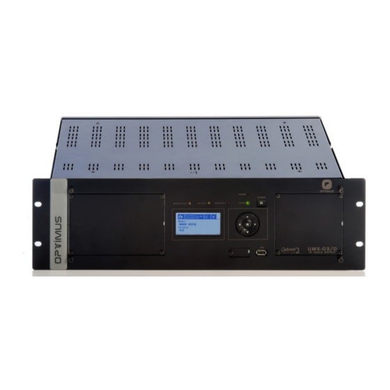
Incorporates an internal Micro SD memory with a capacity of 15 GB to store audio files to be used as pre- recorded messages. These messages can be recorded / updated remotely via IP, using the PA Manage software. UMX-03/0 version 4.3.000.5... -
Page 5: Front View
Emergency Mode. (8) Display (4) Buzzer (9) CONSOLE connector The UMX-03/0 incorporates a buzzer that generates an Mini USB connector. Allows monitoring the system. Only acoustic signal when an alarm is received. specialised personnel. (5) POWER indicator (10) Front USB for inputting music Indicates that the unit is receiving power. -
Page 6: Power And Control Module
If you wish, the system may monitor these contacts (short-circuit or open line detection). To connect follow figure 5. If you wish to monitor the contact, follow figure 6. Figure 5 Figure 6 INPUT CONTACT CONNECTION INPUT CONTACT CONNECTION WITHOUT MONITORING WITH MONITORING UMX-03/0 version 4.3.000.5... - Page 7 SW1. CONFIGURATION OF THE OUTPUT CONTACTS Figure 10 CONTACT B DIPSWITCH A/B DRY REFERENCED TO PRIMARY NUMBER CONTACT (*) GROUND POWER OUTPUT CONTACT 1 OUTPUT CONTACT 2 OUTPUT Figure 11 CONTACT 3 SECONDARY POWER * FACTORY SETTINGS UMX-03/0 version 4.3.000.5...
-
Page 8: Placement Of The Battery
10) BUS AUDIO LINK Audio bus expansion connector. it is used for connecting the UMX-03/0 to the UMX-03/0E units. To accomplish this use 34 way flat ribbon cable with 2x17, 2.54mm IDC connectors. When installing the cable be careful to install the connectors in the same position and side of the flat ribbon cable (see figure 13). - Page 9 SUPPLY 1 and POWER SUPPLY 2). Remove the control module. Insert the battery respecting the polarity indicated in the attached drawing (positive + at the top). Once placed, insert the control module again and turn on the power. UMX-03/0 version 4.3.000.5...
-
Page 10: Connection Between The Umx-03/0 And Umx-03/0E Units
UMX-03/0 Modular audio matrix with IP connection 5. CONNECTION BETWEEN THE UMX-03/0 AND UMX-03/0E UNITS Use the BUS AUDIO LINK and the CAN BUS contacts to connect the UMX-03/0 matrix to the UMX-03/0E units. Figure 12 CAN BUS Figure 13 AUDIO BUS UMX-03/0 version 4.3.000.5... -
Page 11: Connection Of Peripherals To The Can Bus
With the rest of CAN peripherals of the installation (MD-30C, ME-200C, NSD-CAN...) and with an internal speed adapter that the UMX-03/0 device has built-in, the transmission speed is 33.3 kbit/s. This lower speed makes it possible to reach greater distances in the connection between the peripherals and the central one. -
Page 12: Inserting The Cards
Remove the rear blank plate for the slot where the card is to be inserted. All cards occupy a slot except model UMX-2SB which occupies 4 slots (refer to the UMX-2SB manual prior to installing it in the UMX-03/0). Insert the card by fitting it into the slot guides and fasten it by means of the fastening screws. -
Page 13: Display, General View
Allows modifying certain parameters of the unit (IP address, Netmask...), change user, check status of the unit or monitor channels. 9. NAVIGATING THROUGH THE MENUS Using the navigation buttons you can access the different menus of the UMX-03/0. Basic navigation through the menus: - Enter the selected menu... -
Page 14: Structure Of The Menus
OF ZONES AND VOLUME (values between -80 and +4dB) ADJUSTMENTS (values between -80 and +4dB) (values between 0 and 5) SETTINGS MENU (values between -80 and +4dB) (Only if it incorporates module ME-200B) (values between 0 and 30) UMX-03/0 version 4.3.000.5... -
Page 15: Commissioning The Unit
To commission the desktop paging system we must send configurations to it via an Ethernet connection. Accomplishing this requires a PC equipped with a network card and connected to the UMX-03/0 unit through a switch or directly using a network cable. -
Page 16: Operations From The Front Pannel
The unit has a USB port on the front panel for use as a musical program input. To do this, connect to this port an external memory that contains audio files in MP3, WAV or OGG format. Through the P.A. Manager software you can configure the parameters corresponding to this music program (random playback of audio files, music activated or deactivated by zones...). UMX-03/0 version 4.3.000.5... -
Page 17: Volume Zones Adjustment
3’. The display shows the list of zones whose volume is affected by the change. You can check the list by using / keys. Press OK to continue. 4’. Using the / keys to set the desired volume between +4 and -80dB. Press OK to save. UMX-03/0 version 4.3.000.5... -
Page 18: Stop Or Activate All The Music Channels Of The Area
Press again, and using the navigation keys / , select APPLY to apply the new settings or CANCEL to discard the changes. 10. Press OK. Repeat this process for each of the music channels you want to configure. UMX-03/0 version 4.3.000.5... -
Page 19: System Alarms
SYSTEM FAULT indicator light: Front yellow LED. Illuminates when the Mother Board unit detects an error in its firmware itself or if CPU cannot start the application or O.S. • Information on the UMX-03/0 display via the alarms tab, displaying a text chain comprised of: Name of the unit sending the alarm: It will Number of alarms... - Page 20 POWER FAIL Indicates a failure of the primary power Check the primary power by ensuring to the UMX-03/0. the UMX-03/0 is receiving 24 VDC through the POWER SUPPLY 1 terminal strip (see figure 3, number 8). AUX. POWER POWER FAIL...
- Page 21 RECOVERY THE ALARM ME-200B NOT DETECTED Module ME-200B is not detected. If the UMX-03/0 incorporates the ME- 200B module, disconnect the power supply and check the internal connec- tions between the ME-200B module and the UMX-03/0. If the UMX-03/0 does not incorporate an ME-200B module, disable this func- tionality in the unit's web configuration.
- Page 22 (n= Number of configurations of the installation. slave, id.) If the value is 0, remove the card from the UMX-03/0 or the unit is a UMX-03/0E chassis UMX-03/0) (p= Slot occupied by the card) "ZONE NAME"...
-
Page 23: Technical Characteristics
SD memory for pre-recorded messages 16 GB Power supply 24 VDC. Dual power supply (primary and secondary). Consumption 730 mA (without cards). Weight 8.5 Kg Finishes RAL9005 iron painted black Measurements 482.6 (width) x 133 (height) x 280 (depth) Rack units UMX-03/0 version 4.3.000.5... -
Page 24: Optimax 2 System Network Specifications
Ports for the SECURE communication services used in the OPTIMAX2 system: Protocol Multicast address Port Others TCP (unicast) TFTP UDP (unicast) Optional TCP (unicast) Between 135 and 139, and 445 Optional UDP (unicast) Between 135 and 139, and 445 FTPS TCP (unicast) UMX-03/0 version 4.3.000.5... - Page 25 Specifications of the Switch/Router for LAN and WAN networks Protocols: TCP/IP For control/signalling/monitoring status UDP Unicast for Local Audio UDP Multicast for Global Audio Multicast snooping: Multicast filtering IGMP v2 For large installations: Multicast Routing (Spanning Tree) Capable to handle TOS (Type Of Service) UMX-03/0 version 4.3.000.5...
-
Page 26: Software And Firmware Versions
Version 4.3 Optimax Flasher software Version .6626 17. DOCUMENT VERSION TRACKING Reference system Type of Document Confidentiality OPTIMAX 2 / UMX-03/0 Installation and operating guide Date Modifications Content Written by: 4.2.000 April 2017 Translation of the Spanish language version 4.2.000 R+D Department 4.3.000.5... -
Page 27: Guarantee
Tel. 902 151 96 / 972 203 300 The guarantee shall not be valid whenever the following is observed: Fax. 972 21 84 13 • Amendments or corrections made to the details of the guarantee certificate e-mail:girona@optimus.es 1999/44/CE or purchase invoice. UMX-03/0 version 4.3.000.5...
Need help?
Do you have a question about the UMX-03/0 and is the answer not in the manual?
Questions and answers