Table of Contents
Advertisement
Quick Links
DATE:
DOCUMENT NO:
REVISION:
PREPARED BY:
76-02-103 Rev.C
WC-SERIAL USER MANUAL
WC-Serial
User Manual
19
th
76-02-103
C
Paul Ingram
Metrodata Ltd
Laxton House, Crabtree Office Village
Eversley Way, Egham Surrey, TW20 8RY, UK
Tel +44 1 784 744700
Fax: +44 1 784 744701
E-Mail: support@metrodata.co.uk
May 2021
Page 1 of 17
Advertisement
Table of Contents

Summary of Contents for Metrodata WC-Serial
- Page 1 WC-SERIAL USER MANUAL WC-Serial User Manual DATE: May 2021 DOCUMENT NO: 76-02-103 REVISION: PREPARED BY: Paul Ingram Metrodata Ltd Laxton House, Crabtree Office Village Eversley Way, Egham Surrey, TW20 8RY, UK Tel +44 1 784 744700 Fax: +44 1 784 744701 E-Mail: support@metrodata.co.uk...
- Page 2 Further, Metrodata Ltd reserves the right to revise this publication and to make changes from time to time in the content hereof without obligation of Metrodata Ltd to notify any person of such revision or changes.
- Page 3 WC-SERIAL USER MANUAL Document History 10/04/2017 Document Created 26/04/2017 Document Released 18/01/2019 Minor corrections 19/05/2021 Minor corrections 76-02-103 Rev.C Page 3 of 17...
-
Page 4: Table Of Contents
EN55022 Statement ................8 1.3.2 FCC Declaration ..................8 WEEE Directive ..................... 8 RoHS Compliance ..................8 INSTALLATION ....................9 WC-Serial Rear Panel ................... 9 2.1.1 Mains Power ..................9 2.1.2 DC Power ....................9 2.1.3 User LAN Ports ..................10 2.1.4... - Page 5 Switch 6, Speed ................14 2.2.6.3 Switch 8, Auto Negotiation .............. 14 Rack mounting .................... 15 WC-Serial Fault Finding ..................16 RED LED ON, WAN Fault ................16 GREEN LED FLASH, LAN Fault ..............16 RED LED FLASH, WAN and LAN Fault ............16 YELLOW LED ON, WAN Sync Alarm ............
-
Page 6: Introduction
WAN link. There is internal packet buffering to smooth out bursty traffic. WC-Serial units are used in pairs, one on either side of a WAN link due to the proprietary encoding of the serial data. -
Page 7: Wc-Serial
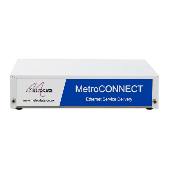
WC-SERIAL USER MANUAL 1.1 WC-Serial The WC-Serial is a compact unit as shown occupying half a shelf in a traditional 19inch rack. All connectors and LED status indicators are accessible from the rear of the unit. 1.2 Safety The WC-Serial must not be connected to cabling which would be required by BS6701 to equipped with over voltage protection. -
Page 8: En55022 Statement
WC-SERIAL USER MANUAL 1.3.1 EN55022 Statement The WC-Serial is a Class A product. In a domestic environment, this product may cause radio interference, in which case the user will be required to take adequate measures. 1.3.2 FCC Declaration This equipment has been tested and found to comply with the limits of the Class A digital device, pursuant to Part 15 of the FCC rules. -
Page 9: Installation
The WC-Serial is available with either AC Mains or DC power options. 2.1.1 Mains Power The WC-Serial has an internal power supply and is supplied via an IEC mains power socket. The WC-Serial operates over the wide range 100 to 250V AC and draws less than 6 watts. -
Page 10: User Lan Ports
WC-SERIAL USER MANUAL 2.1.3 User LAN Ports The WC-Serial has two User LAN ports presented on RJ45 connectors. The two ports support 10/100BaseT with auto MDI/MDI-X crossover switching. The ports are configured as a pair using the bit switches on the underside and therefore may be manually configured with auto negotiation disabled. -
Page 11: Serial Led's
WC-SERIAL USER MANUAL 2.1.6 Serial LED’s The Serial interface has two status LED’s as described below 2.1.6.1 Transmit (TX) LED The transmit LED is set to pulse on for 100mS whenever a packet is transmitted on the serial interface. With a very low packet rate, the LED may flash, but with normal traffic conditions the TX LED will be on all the time. -
Page 12: Base Label And Bit Switches
WC-SERIAL USER MANUAL 2.2 Base Label and Bit Switches On the underside of the WC-Serial there are bit switches which may be used to configure certain functions within the unit. The bit switches are used to configure the operational mode of the WC-Serial and will be effective immediately. -
Page 13: Switch 1, Data Inversion
WC-SERIAL USER MANUAL 2.2.1 Switch 1, Data Inversion In normal operation the WC-Serial would be operated with the data in normal mode with a ‘1’ representing a Mark, and ‘0’ representing Space. This switch allows this to be inverted. 2.2.2 Switch 2, TX Clock Inversion In normal operation the WC-Serial would be operated with the transmit clock in the normal state. -
Page 14: Network Port Configuration
2.2.6 Network Port Configuration Bit switches 6 to 8 are used to configure the setting for the LAN ports of the device and are used on installation to ensure the WC-Serial physical interface matches that of the host port it will connect to. -
Page 15: Rack Mounting
19 inch rack using the rack mounting kit, part number 80-05-256. To mount the WC-Serial in the 19 inch rack mount adaptor first remove the two M3x12 screws and washers from the rear panel of the unit. Then align the WC- Serial rear panel with the mounting bracket, and secure the unit to the adaptor using the previously removed screws. -
Page 16: Wc-Serial Fault Finding
WC-SERIAL USER MANUAL 3 WC-Serial Fault Finding The WC-Serial is designed to be a simple ‘plug and play’ device which uses an auto sensing cable to configure the serial port. Serial port timing is provided by the attached DCE (modem) equipment. -
Page 17: Yellow Led On, Wan Sync Alarm
The WAN SYNC alarm indicates that both transmit and receive clocks are present but it is not possible to synchronise to the received serial. The WC-Serial expects to receive an HDLC stream and SYNC is declared once flags have been detected and the HDLC packet CRC error rate is low.
Need help?
Do you have a question about the WC-Serial and is the answer not in the manual?
Questions and answers