
Related Manuals for SONOPLOT MICROPLOTTER Proto

Summary of Contents for SONOPLOT MICROPLOTTER Proto
- Page 1 ™ P ICROPLOTTER ROTO ANUAL EVISION 3030 L AURA UITE , WI 53562 IDDLETON (608) 824-9311 CONTACT SONOPLOT...
-
Page 3: Table Of Contents
ONTENTS Introduction Ultrasonic fluid dispensing Surface height sensing Precision robotic positioner Installation Unpacking and setup Positioning system Connecting the system to a computer Installing the SonoGuide software Loading a dispenser cartridge Powering on the system Sample Application One-component oligonucleotide microarray Wires from nanometallic inks SonoGuide Overview... - Page 4 Dispenser refurbishing Revision History...
- Page 5 SonoPlot, the SonoPlot logo, SonoDraw, SonoGuide, and Microplotter, among others, are trademarks of SonoPlot, Inc. in the United States and other countries. Other parties’ trademarks or service marks are the property of their respective owners and should be treated as such. The Microplotter products and accessories are protected by one or more of the following U.S.
-
Page 7: Introduction
NTRODUCTION Congratulations on your purchase of a SonoPlot Microplotter instrument! A Microplotter system is a leading-edge tool for the fabrication of biological microarrays, polymer electronics, or any other application that requires precise and accurate dispensing of extremely small liquid volumes. It can dispense picoliters of a wide variety of solutions onto almost any planar surface in discrete spots or continuous traces such as lines or arcs. - Page 8 Fluid deposition via ultrasonic pumping A Microplotter system also has the unique capability of dispensing continuous lines. This is accomplished by starting as if to create a spot on a surface, but not deactivating the dispenser after fluid contact has been made with the surface. Instead, the dispenser is moved along the surface in a straight line, leaving behind a smooth line wherever it passes.
-
Page 9: Surface Height Sensing
As you read through the following chapters, you will learn how to install, configure, and operate your Microplotter Proto instrument in order to take advantage of its unique capabilities in your line of research or development. -
Page 11: Installation
NSTALLATION Unpacking and setup The Microplotter Proto instrument will come in one large crate containing the system itself, the control electronics, and a box of smaller components. Warning: The positioning system is heavy, and should be lifted by more than one person. - Page 12 Rear view of control electronics box Power cable Positioning stage X, Y, and axis cables. These are interchangeable, and can be attached in any order. USB cable to control computer...
-
Page 13: Connecting The System To A Computer
RJ-11 cable to dispenser Connecting the system to a computer Once the cables have been connected to the electronics box, insert the USB cable from the electronics box into a USB port on your computer and also insert the USB cable from the CCD camera to a different USB port on your computer. -
Page 14: Installing The Sonoguide Software
Follow the steps below to install the SonoGuide software on your computer. MacOS Go to www.sonoplot.com/downloads and click on the SonoGuide for Mac link. Download the SonoGuide.DMG file. Once downloaded, double click on the DMG file. The SonoGuide Installer window will appear on... - Page 15 Drag the SonoGuide icon over to the Applications folder. SonoGuide has now been installed to your MacOS computer. Windows Go to www.sonoplot.com/downloads and click on the SonoGuide for Windows link. Download the SonoGuideInstaller.exe. Once downloaded, run the installer. Select the Installation Folder.
- Page 16 Select the components to install.
- Page 17 Select where you would like to create SonoGuide’s shortcut. SonoGuide is ready to be installed.
- Page 18 Click Install to start installing SonoGuide. Once the installer has finished installing SonoGuide, click on Finish. SonoGuide has been installed and is ready to use.
-
Page 19: Loading A Dispenser Cartridge
Loading a dispenser cartridge Warning: Avoid contacting the exposed glass needle to any surface, as even a slight touch can shatter the fragile tip. To load a dispenser cartridge, carefully place the notched side of the dispenser onto the printhead, as shown. -
Page 20: Powering On The System
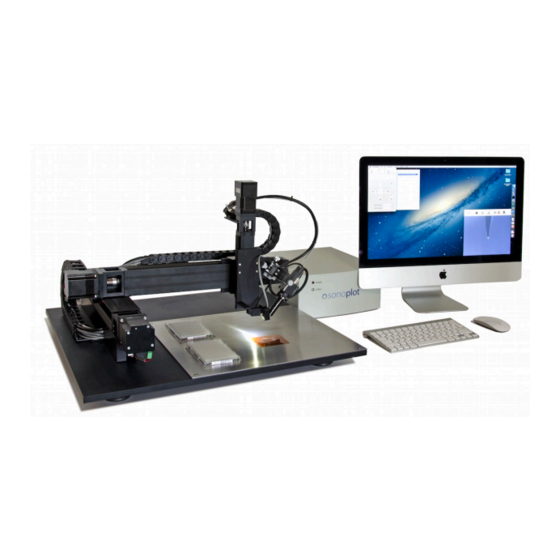
Powering on the system Once all components have been assembled, the control electronics are plugged in, and the SonoGuide software has been installed, it is possible to power on the system and start dispensing. To turn on the control electronics flip the power switch for the control electronics on the rear left as you face the front of the control box. - Page 21 Fully installed Microplotter Proto system ...
-
Page 23: Sample Application
AMPLE PPLICATION In this chapter, two sample applications of a Microplotter system will be used to illustrate its capabilities and the basic functions of its hardware and software. The first, a deposition of a one-component oligonucleotide (DNA) microarray, serves as an introduction to the operation of a Microplotter instrument and its software while providing an example of a common application for this technology within the biological sciences. - Page 24 Before you start the dispensing process, you will need to calibrate the cant (level) of the surface to be dispensed onto. Place a treated glass microscope slide in an appropriate slot on the deck (or platen) of the Microplotter system. If your deck does not support microscope slides, either replace the deck with one that does or use a different substrate material.
- Page 25 This should take a few seconds, after which a notification will appear that confirms the calibration of the dispenser. The camera may not be focused on the tip of the new dispenser. Adjust the three thumbscrews on the camera mount to bring the tip of the dispenser into focus. If the contrast of the image is poor, the image is too bright or dark, or the hue is wrong, you can adjust the settings of the camera by opening the Camera Controls from the windows options and adjusting the sliders in the dialog that will appear.
- Page 26 The sizes of the large and small steps are set by the Large Step and Small Step text input boxes. All values are in microns and can be set differently for each axis. Set the large step to 10000 microns (one centimeter), to move one centimeter at a time, and grossly position the robot above the upper-left corner of the microscope slide.
- Page 27 Open the surface calibration window by clicking on the Calibrate Surface button. Under the Distance to calibrate group,set the distance to calibrate along the X axis to 20000 microns (20 mm is just a little less than the full 25 mm width of a typical microscope slide) and set the distance to calibrate along the Y axis to 70000 microns (again, 70 mm is just shorter than the full 75 mm height of a microscope slide).
- Page 28 If not already set at this value, change the Dispensing strength to be 1 V and the Spraying strength to be 12 V. These settings regulate the ultrasonic pumping action within the dispenser while dispensing fluid and emptying the glass needle, respectively. The values listed should be good defaults for aqueous solutions within a dispenser having a tip inside diameter of between 10 and 50 microns.
- Page 29 To save the location of this well, open the Solutions toolbar item and the Solutions Settings window. This will bring up a windows for setting solution locations. Click the + button to add a new solution to the list. Enter in a name of Solution 1 and hit Return when you are done.
- Page 30 If it does not, the glass tip may be clogged with a small dust particle. To clear this, open the dispenser control window again by selecting the menu item Dispenser | Show dispenser controls. Click first on the Dispense button to drive the dispenser at its more gentle settings. Wait for a few seconds.
-
Page 31: Wires From Nanometallic Inks
Once fluid contact has been made, it is time to start the pattern. Choose the menu option File | Open Pattern... and pick the pattern you drew earlier. Open the Pattern window and assign the solutions saved to the associated layer. Repeat until all solutions in the pattern are accounted for. - Page 32 similar wells. Check the solvent resistance of your well material first before using these solvents. Nanometallic inks using ethanol or water as a solvent can safely be loaded in the wells of a standard microtiter plate. Another concern regarding inks is their volatility. While it can work with a wider range of solutions than inkjets or similar competing technologies, a Microplotter instrument still has difficulty with highly volatile solvents, such as acetone.
-
Page 33: Sonoguide
UIDE Overview SonoGuide is the main control interface for the Microplotter Proto instrument. Movement of the positioning system, calibration of substrates, and operation of the dispensers are all controlled through this piece of software. It was designed with the intention of providing the maximum amount of flexibility to the end user in order to enable many novel applications. - Page 34 Once SonoGuide establishes communication with the positioner, it will next check to determine whether the positioner has been homed. When the positioner has been turned on, its motors need to seek to a standard home position before they can be commanded to move anywhere. This is intended to provide a constant starting location for the absolute positioning of the dispenser head.
-
Page 35: Directional Controls
The graphical user interface has several windows initially, including: • Directional controls • Saved positions • CCD camera display window • Working area of the positioner These will be described in order, starting with the directional controls. Directional controls The window for the directional controls appears as follows: These controls allow you to move the positioner manually in a stepwise fashion or a continuous fashion. -
Page 36: Toolbar Items
move the positioner in small steps, while the double-arrow ones move the positioner in large steps. The step sizes are specified, in microns, by the Large step and Small step text boxes. For reference, 1000 microns = 1 mm and 10000 microns = 1 cm. Unless otherwise indicated, all distance inputs in the control software are specified in microns. -
Page 37: Saving Positions
Saving positions It is often useful to be able to save positions that can be returned to quickly at a later time. A window of the interface is provided to allow you to do this. This panel presents a list of previously saved positions, their associated coordinates, and a set of 3 buttons. -
Page 38: Robotic Positioner Settings
Robotic positioner settings The robotic positioner can be moved manually via the controls in the main interface, but it is possible to have even finer control of movement properties by using the Positioner configuration window accessed under the SonoGuide | Tools | Motor Settings menu option. - Page 39 Warning: Changing the tuning values can lead to positioner inaccuracy or complete instability of the positioning system. Only alter them if necessary to correct positioning problems or when instructed by SonoPlot personnel. Additionally, this window allows you to import motor settings and export these settings which...
-
Page 40: Printing Patterns
File | Open Pattern... menu item. You can also open recently printed patterns from the File | Open Recent menu. Both SonoPlot’s .pattern files and AutoCAD DXF format files can be loaded in this manner. Once a pattern has been loaded, it will... - Page 41 The feature width specified below the pattern dimensions is used to make the preview more accurately reflect what will be printed, and does not control the actual dispensing size. It also is used to set the spacing between lines when drawing a filled rectangle. Each layer in the pattern or DXF file is listed below these options.
- Page 42 The first item lets you select the Dispense Mode. Here you can select the system to use the spraying action instead of the more gentle dispensing actuation when printing. This is occasionally used to coat larger areas with a less controlled spray of material. Then there are three selectable options for how the pattern is to be printed.
-
Page 43: Camera Display
aperture dispenser. As a rule of thumb, a 200 micron pickup height works well for dispenser apertures up to 50 microns wide and a 1000 micron pickup height works for anything above that. When you are ready to print, you can click on the Print button. The controlling computer will automate the dispensing process from beginning to end. -
Page 44: Camera Settings
file and allowing you to give it a name (the default is temp.mp4). Once you click OK, the video will start recording to disk. When you are finished recording from the camera, click on the Stop recording menu item under the Camera menu or click on the Stop toolbar item. The video files saved by SonoGuide are recorded into ISO standard MPEG4 files with an MP4 extension. - Page 45 Near the top of this dialog is an option to Automatically adjust light sensitivity. If selected, the software will attempt to analyze the image coming from the camera and adjust the gain, brightness, and exposure settings of the camera to produce an optimal picture under variable lighting conditions.
-
Page 46: Dispenser Control
• Saturation - The intensity of the color response of the camera can also be controlled using this setting. Low values can lead to a grayscale image and high values can cause color bleeding. • White balance, Blue / U - The camera uses a color CCD and the color balance of that CCD can be controlled by manipulating the blue and red (U and V) components of the image. - Page 47 For dispensing, setting the voltage to 0 will cause only a very small pulse to be applied, which can be ideal for dispensing that is primarily driven by surface tension. This can yield very low variabilities for droplets dispensed on chemically uniform surfaces. However, it can lead to missing droplets.
-
Page 48: Dispenser Calibration
Dispenser calibration When a new dispenser has been connected to the system, it needs to be calibrated before it can be used to deposit fluid or sense the physical height of a surface. From time to time, the dispenser may need to be recalibrated due to changes in its contents or drift in the system. The connection of a dispenser to the system is not automatically detected. -
Page 49: Solution Well Locations
A sharp dip, followed by a spike, occurs at around 440 kHz. This is a resonance within the dispenser. The sharper the dropoff, in the resonance, the stronger it is. Several smaller resonances can be seen, but those are weaker than the one at around 440 kHz. The exact resonance frequency is the frequency near the bottom of the dip where impedance is at a minimum. - Page 50 The first window is a list of solutions. Each solution can be selected by clicking on its name. New solutions can be added to the list by clicking the plus button, and old solutions can be removed by clicking the minus button. When first adding a solution, you will be given the chance to edit its name.
- Page 51 If your solutions are not in a micro titer plate, but in custom wells that you have placed on the deck of the system, you will need to manually define their positions. To set up a custom well location, first move the dispenser into the well so that it is taking up solution. Then click on the Use current coordinate as custom position button to set the location of the well.
-
Page 52: Surface Cant Calibration
The last toolbar option is for calibrating the locations of wells within a microtiter plate. If you have changed dispensers, or have switched between 96- and 384-well microtiter plate types, you will need to set the new starting location of the first well in the microtiter plate on the system’s deck. -
Page 53: Rotational Calibration
Enter the width and height of the area that you would like to be calibrated in the X and Y directions (in microns). If calibrating a sample, choose distances that are a little less than the dimensions of the sample, keeping the measurements within the bounds of that sample. Once the proper distances have been set, bring the dispenser to approximately 1 mm over the top left corner of the sample, then click on Use current position next to the Top-Left option. -
Page 54: Diagnostics
current position button next to the first position in the dialog box. Move the positioner to the second point (Top-Right) and click on the Use current position button next to the second position in the list. The angle at which the pattern will be rotated, based on these points, is displayed at the bottom of the dialog box. - Page 55 The red line indicates the threshold for surface sensing. If the signal is not strong enough to cross this threshold, the software will not detect contact of the dispenser with the surface. In that case, recalibrate the surface sensor as described in the previous section. When retracted from the surface, the signal should sharply drop off once again.
- Page 56 Advanced label. This will expose a series of realtime readouts from the ultrasonic frequencies used to determine when contact has been made with a surface. This can be used by SonoPlot personnel to help figure out why a given dispenser may not be behaving properly.
-
Page 57: Useful Keyboard Shortcuts
Useful Keyboard Shortcuts The SonoGuide software includes a series of useful keyboard shortcuts: Find Surface: Ctrl/Cmd + F Set A1 position: Ctrl/Cmd + 1 Move to desired position: Ctrl/Option + click Go Home: Fn + Left arrow (MacOS) Go Home: Home key (Windows) When using Trackball: Hold SHIFT to move 10X ... -
Page 59: Troubleshooting
ROUBLESHOOTING The dispenser will no longer take up fluid This may be the result of clogging within the dispenser. To resolve this, move the dispenser back into the source fluid well. Open the dispenser controls by choosing the Dispenser | Show dispenser controls menu item or the Control dispenser toolbar item. - Page 60 As the dispensers are very fragile, you must be careful to ensure you are not putting too much pressure on the dispensing tip. Sonoplot suggests moving the tip down to a short distance above the surface, then stepping down in 10 micron steps until a fluid bridge is made between the tip and the surface.
- Page 61 If the impedance scan is a series of noisy peaks between 0 and 20 ohms, the dispenser is short-circuited. At this time, the only solution is to replace the dispenser. NOTE: A short circuit is possible if you have been working with a metallic ink, and the ink has formed bridge across both sides of the piezoelectric element (the gray rectangle to which the glass capillary is attached).
-
Page 63: Technical Specifications
ECHNICAL PECIFICATIONS Feature size 20 µm - 200 µm Feature types Droplets and contiguous lines Deposition volume ≥ 1 pL Deposition variability As low as 10% Viscosity ≤ 450 cP Positioning 31 x 31 x 7 cm (X, Y, Z axes) 10 µm resolution Calibration Automatic surface height calibration... - Page 65 ISPENSER REFURBISHING The glass micropipette on the dispenser can be replaced by the user. Open the dispenser cartridge assembly by loosening the two black plastic screws on the front of the dispenser assembly. Remove the dispenser cover. Remove the old glass micropipette by removing the RJ 11 wire assembly and dipping the piezo/ glass pipette end of the RJ 11 wire in acetone until the glue holding the micropipette is dissolved.
- Page 67 EVISION ISTORY Version 1.3 •Updated SonoGuide chapter to include new version UI/features. Version 1.2 • Added the <polygon> pattern element to Chapter 9. Version 1.1 • Revised the SonoGuide chapter to include the new pattern preview window and DXF import capabilities.
Need help?
Do you have a question about the MICROPLOTTER Proto and is the answer not in the manual?
Questions and answers