
Summary of Contents for ST Group ST 100
- Page 1 ST 100 NEARFIELD SEARCH RECEIVER USER MANUAL ST Group, Ltd. St. Petersburg, Russia +7 (812) 412 -3321 info @sm ersh.pr o www. spymarket.com...
-
Page 2: Table Of Contents
Contents CONTENTS General information………………………………………….…………………………………………….… Purpose and Capabilities………………………..…………………….………………………………………………………………… Kit….……………………………………………………………………………………………………………………………………..Description of Components……………………………………………………………………………………………………………… Power supply…………………………………………………………………………………………………………………………………… Specifications…………………………………………………………………………………………………………………………………… Interface Settings…………….………………………………………………………………………………. Turning on/off……..…………………………………………………………………………………………………………………………… The Main Menu…………………………………………………………..………………………………………………………………….… Information Line………………………………………………………………………………………………………………………..……. Settings (SERVICE Mode)…….….……………………………………………………………………………………………………… Channel#1. SEARCH RECEIVER (20 MHz - 6 GHz)………………………………………………….. PANORAMA mode ……………..……………………………………………………………………………………………………………. DIFFERENTIAL mode ……………………………………………………………………………………………………………………… 3.2.1 SIGNAL ANALYSIS AT A FIXED FREQUENCY function….………………………………..………………………………... - Page 3 Contents 8.2.2 Signal source localization………………………………………………………………………………………………………………… Recommendations for using an INFRARED DETECTOR…………………………………………………………………. 8.3.1 Search for signals………………………………………………………………………………………………….………………………… 8.3.2 Selection of "FALSE" signals …………………………………………………………………………………………………………… Recommendations for using parametric detector……………………………………………………………………….. Software………………………………………………………………………………………………………..… Purpose…………………………………………………………………………………………………………………………………………. Functionality ………………………………………………………………………………………………………………………………..…. PC system requirements……………………………………………………………………………………………………………….. Installation……………………………………………………………………………………………………………………………………… SELECTED RANGES mode……………………………………………………………………………………………………………….. MOBILE DEVICES mode ……………………………………………………………………….…………………………………………...
-
Page 4: General Information
General information 1. GENERAL INFORMATION The manual describes the principle of operation of the ST 100 (hereinafter "ST 100" or "Device"). The manual contains hyperlinks that allow you to go to the text fragments of interest. 1.1. PURPOSE AND CAPABILITIES ST 100 is designed to search, identify and localize wireless eavesdropping devices. -
Page 5: The Kit
Cable for connecting the main unit to the USB port of the PC ………………………….. Parametric detector ST 100 P………………………………………………………………………………. Screws for attaching the parametric detector to the main unit.………………………… Mini-antenna.…………………………………………………………………………….……………….………… Case ……………………………………………………………………………………………………………………… Fig.1 For transportation and storage of the ST 100 the shockproof case is used. -
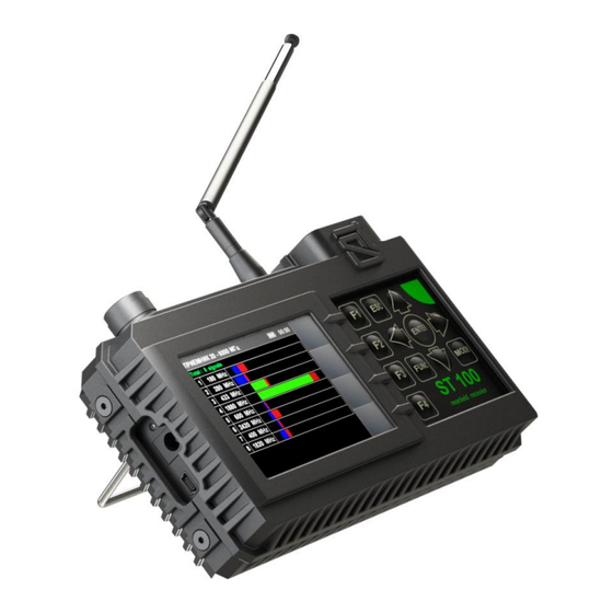
Page 6: Description Of Components
General information Fig.2 Numbers indicate the elements of the kit, laid in a certain place of the lodgment. The designations correspond to the numbering presented in item 1.2. 1.3. DESCRIPTION OF COMPONENTS 1.3.1. MAIN UNIT Purpose of the main unit: •... - Page 7 General information Fig.3 In fig.3 Component Display Keyboard Power switch / volume control Headphone jack Parametric detector connector IR detector sensor Antenna connector Support Serial number plate Connectors for attaching a parametric detector Built-in speaker Charger connection indicator Charger socket Mini-USB connector for PC connection...
-
Page 8: Power Supply
1.3.6. USB FLASH DRIVE MP3 files (for PTS), this Manual and the ST 100 software recorded on the USB flash drive. 1.4. POWER SUPPLY The device operates on a built-in battery, the charge level of which displayed using an indicator in the information line (Fig.6, item... -
Page 9: Specifications
General information 1.5. SPECIFICATIONS SEARCH RECEIVER (20 МГц – 6 ГГц) frequency range, MHz 20…6000 bandwidth, MHz 0,1/1/20 demodulation input impedance, Ohm scanning speed, GHz/sec uneven frequency response, dB ±6 minimum level of the detected signal, dB dynamic range, dB gain control (fixed values), dB 0, 8, 16, 24, 32, 40 antenna... -
Page 10: Interface Settings
3). Screen view is in Fig.4. Fig.4 On the screen: company logo, device name (ST 100) and firmware version. It is necessary to press any button on the keyboard for continue. 2.2. THE MAIN MENU The MAIN MENU is shown in Fig.5 Fig.5... -
Page 11: Information Line
Interface settings 2.3. INFORMATION LINE In the upper part of the screen, there is an information line (Fig.6). Fig.6 In Fig.6: Channel is on Videocamera signal detection indicator Accumulator charge level Current time in a format "HH:MM" 2.4. SETTINGS (SERVICE MODE) This mode is design to set the date, time and interface language (Russian or English). - Page 12 Interface settings 2.4.1. DATE SETTING Using the buttons, set the cursor to the "DATE" item and press ENTER. The date setting menu (Fig.8) in the "DD-MM-YYY" format will appear on the screen. Fig.8 Use the buttons to set the cursor to the "DAY" menu item and use the buttons to set the desired value.
-
Page 13: Channel#1. Search Receiver (20 Mhz - 6 Ghz)
Channel#1. SEARCH RECEIVER (20 MHz - 6 CHz) 3. CHANNEL#1. SEARCH RECEIVER (20 MHZ - 6 GHZ) The channel is designed to detect radio signals of analog and digital radio transmitting eavesdropping devices in the 20 MHz -6 GHz range. To receive radio signals, two antennas are used: a telescopic antenna (Fig.1, item 2) and a mini-antenna (Fig.1, item 9). -
Page 14: Panorama Mode
Channel#1. SEARCH RECEIVER (20 MHz - 6 CHz) MODES: PANORAMA mode DIFFERENTIAL mode AUTOMATED mode LOCALIZATION Mode 3.1. PANORAMA MODE Functionality: signal analysis in AUTOMATED mode; signal analysis in DIFFERENTIAL mode; search for a signal source using the LOCALIZATION mode; ... - Page 15 Channel#1. SEARCH RECEIVER (20 MHz - 6 CHz) Scroll bar Upper limit of the set swath Set gain value Controls: Button Action ESC, MODE Switch to MAIN MENU ENTER Turn on SIGNAL ANALYSIS AT A FIXED FREQUENCY function Marker control Scaling a panorama relative to a marker Turn on LOCALIZATION mode Turn on AUTOMATED mode...
-
Page 16: Signal Analysis At A Fixed Frequency Function
Channel#1. SEARCH RECEIVER (20 MHz - 6 CHz) DIFFERENTIAL mode is turn on from the PANORAMA mode (Fig.12) by pressing the F3 button, the field of which will become lighter. The device screen is shown in Fig.14. Fig.14 In Fig.14: SEARCH RECEIVER (20 MHz - 6 GHz) is on Indication of turn on of the DIFFERENTIAL mode Constant differential signal detected in the last scan cycle (purple) - Page 17 Channel#1. SEARCH RECEIVER (20 MHz - 6 CHz) The screen view is shown in Fig.15. Fig.15 In Fig.15: SEARCH RECEIVER (20 MHz - 6 GHz) is on Signal level on fixed frequency SETTING "0" function indicator Bandwidth value OSCILLOSCOPE function indicator Functionality: ...
-
Page 18: Setting "0" Function
Channel#1. SEARCH RECEIVER (20 MHz - 6 CHz) 3.2.2. SETTING "0" FUNCTION The function is intended to localize the signal source detected when using the SIGNAL ANALYSIS AT A FIXED FREQUENCY function. The use of this function is especially effective when searching for sources of strong signals, when even with the minimum value of the gain the signal level indicator goes off scale and the localization of the signal source is difficult. -
Page 19: Search For Video Camera Signals Function
Channel#1. SEARCH RECEIVER (20 MHz - 6 CHz) In Fig.16: SEARCH RECEIVER (20 MHz - 6 GHz) is on Fixed frequency Time division value Oscillogram of the demodulated signal at a fixed frequency Activity indicator OSCILLOSCOPE function Functionality: determination of the time parameters of the demodulated signal; ... -
Page 20: Automated Mode
"NON-DANGEROUS" - signals from base stations of mobile communication systems; "DANGEROUS" - signals of wireless mobile devices; "UNKNOWN" - all other signals. The ST 100 software allows you to assign a "DANGEROUS" or "NON-DANGEROUS" attribute to certain frequency bands. - Page 21 Channel#1. SEARCH RECEIVER (20 MHz - 6 CHz) If the received signals fall into these ranges, they are highlighted in the table with the corresponding color ("NON-DANGEROUS" - green, "DANGEROUS" – red, "UNKNOWN" – white). The screen view after turning on the mode is shown in Fig.18. Fig.18 In Fig.18: SEARCH RECEIVER (20 MHz - 6 GHz) is on...
-
Page 22: Frequency Tuning Function
Channel#1. SEARCH RECEIVER (20 MHz - 6 CHz) Controls: Button Action Return to the previous mode MODE Switch to MAIN MENU FUNC Sorting signals Table cursor control Turn on SETTING "0" function Setting the bandwidth and turning on the FM demodulator Turn on OSCILLOSCOPE function Turn on/off gain setting ENTER... -
Page 23: Search For Video Camera Signals Function
Channel#1. SEARCH RECEIVER (20 MHz - 6 CHz) 3.4.2. SEARCH FOR VIDEO CAMERA SIGNALS FUNCTION In AUTOMATED mode, the function of searching for video cameras signals is implemented. It turns on automatically when the table cursor is placed on a table row. If the signal matches certain parameters, the video camera detection indicator appears (Fig.18, item 2). -
Page 24: Channel#2. Search Receiver (6 Ghz - 12 Ghz)
Channel#2. SEARCH RECEIVER (6 GHz - 12 GHz) 4. CHANNEL#2. SEARCH RECEIVER (6 GHZ - 12 GHZ) The channel is designed to detect analog and digital radio transmission eavesdropping devices in the frequency range 6 GHz - 12 GHz. Signals are received by an antenna located inside the main unit. Analysis of the detected signals is performed using: ... -
Page 25: Channel#3. Search Receiver For Monitoring The Selected Ranges
Channel#3. SELECTED RANGES 5. CHANNEL#3. SEARCH RECEIVER FOR MONITORING THE SELECTED RANGES (SELECTED RANGES) The channel is designed to detect signals from the most common digital communication standards and in user-defined frequency ranges. Ch a n ne l fu nc t io n a l d i a gr a m Fig.21 MODES: ... - Page 26 Channel#3. SELECTED RANGES To receive signals, antennas are used (item 3), connected to the ANT 1 socket on the top panel of the main unit (Fig.10). The channel is turned on from the MAIN MENU, while the MOBILE DEVICES mode is automatically activated.
- Page 27 Channel#3. SELECTED RANGES 5.2. BASE STATIONS MODE The mode allows you to determine the signal levels of digital communication base stations in real time and analyze them. The mode can be turn on from the MOBILE DEVICES mode or USER LIST mode. To turn on the mode, press F2.
- Page 28 Channel#3. SELECTED RANGES Fig.24 Controls: Button Action ESC, MODE Switch to MAIN MENU ENTER Turn on ANALYSIS OF THE DETECTED SIGNAL function Table cursor control Turn on MOBILE DEVICES mode Turn on BASE STATIONS mode Turn on/off GAIN SETTING function FUNC, F3 Not used 5.4.
- Page 29 Channel#3. SELECTED RANGES Fig.25 In Fig.25: SELECTED RANGES is on Digital communication standard Time division value White frame of active window (OSCILLOSCOPE or SPECTRUM ANALYZER) OSCILLOSCOPE Lower limit of the range Frequency value on the SPECTRUM ANALYZER marker SPECTRUM ANALYZER SPECTRUM ANALYZER marker Upper limit of the range Bandwidth...
- Page 30 Channel#3. SELECTED RANGES When it is turned on, the level of the detected signal is taken as "0" and the LEVEL INDICATOR shows the difference value of the signal (the indicator color will turn purple). Use the ENTER button to turn the SETTING "0" function on or off. Controls: Button Action...
- Page 31 Channel#4. INFRARED DETECTOR 6. CHANNEL#4. INFRARED DETECTOR The channel is designed to detect eavesdropping devices transmitting information in the IR-range. The detector sensor is located on the top panel of the main unit (Fig. 3, item The analysis of the detected signals is carried out using: ...
- Page 32 Channel#4. INFRARED DETECTOR 6.1. DIFFERENTIAL MODE DIFFERENTIAL mode is designed to localize the source of the detected IR signal. When the mode is turned on, the level of the detected signal is taken as "0" and the differential signal level is displayed on the level indicator (Fig.25, item To turn on the DIFFERENTIAL mode, press the ENTER.
- Page 33 Channel#5. PARAMETRIC DETECTOR 7. CHANNEL#5. PARAMETRIC DETECTOR PARAMETER DETECTOR is designed to detect working electronic devices, including those that do not transmit information during a search. These devices include: eavesdropping devices using digital channels for transmitting information; cell phones; ...
- Page 34 Channel#5. PARAMETRIC DETECTOR The parametric detector is attached to the main unit with two screws (Fig.1, item 8), as shown in Fig.29 (A). In Fig.29 (B), the parametric detector is installed on the main unit. Fig.29(A) Fig.29(В) At te nt i on ! The parametric detector cable connector is equipped with a clamp. To disconnect the connector, press the button (Fig.
- Page 35 Channel#5. PARAMETRIC DETECTOR The channel is turn on from the MAIN MENU. The screen of the device after switching on is shown in Fig. 32. Fig.32 At the same time, the transmitter and receiver of the parametric detector are turned on, the sound is heard in the headphones.
- Page 36 RECOMMENDATION FOR USE 8. RECOMMENDATIONS FOR USE 8.1. RECOMMENDATION FOR USING THE SEARCH RECEIVERS (20 MHZ - 6 GHZ AND 6 GHZ - 12 GHZ) There are two options for searching for eavesdropping devices: search in the AUTOMATED mode; ...
- Page 37 RECOMMENDATION FOR USE 8.1.2. SEARCH IN THE PANORAMA MODE AND IN THE DIFFERENTIAL MODE PANORAMA mode and DIFFERENTIAL mode are used to search for eavesdropping devices in a difficult electromagnetic environment in the search area. 1. In the tested room turn on the player of the test sound (PTS) and adjust the volume level. 2.
- Page 38 RECOMMENDATION FOR USE Features of the energy method when using SIGNAL ANALYSIS AT A FIXED FREQUENCY function After defining the frequency of "DANGEROUS" signals in DIFFERENTIAL mode, AUTOMATED mode or in PANORAMA mode, the user must turn on SIGNAL ANALYSIS AT A FIXED FREQUENCY function.
- Page 39 RECOMMENDATION FOR USE Fig.34 INTERPRETATION OF DEVICE READINGS IN THE LOCALIZATION MODE In the LOCALIZATION mode, the energy method is used (analysis of the change in the level of the detected signal when the device is moved around the tested room). After turning on the mode and scanning the entire range, a table (Fig.17) with information...
- Page 40 RECOMMENDATION FOR USE The dotted line indicates the "0" (initial) signal level, fixed when the mode was turned on. Ideally, when the mode is turned on, the level of the detected signal should not be displayed in the table, but the signal frequency will be determined (Fig.35, item 1). However, in a real environment, insignificant signal levels can be observed (green indicator).
- Page 41 RECOMMENDATION FOR USE In fig.36 User actions Indication Interpretation Turn on the The received signal level is taken as "0". LOCALIZATION mode The device is Move the device to the The current signal level has increased approaching the signal center of the room compared to the level at point #1 source The signal level is less...
- Page 42 RECOMMENDATION FOR USE GSM1800 1805 - 1880 2110 - 2170 3G low 2010 - 2025 DECT 1880 - 1900 USER LIST Frequency range, MHz ---- 88 - 108 ---- 430 - 450 Using the software, you can correct the composition and parameters of the ranges of mobile devices, base stations and ranges of the user list.
- Page 43 RECOMMENDATION FOR USE 8.2.2. SIGNAL SOURCE LOCALIZATION When using the SELECTED RANGES channel, the signal source is localized using the ANALYSIS OF THE DETECTED SIGNAL function (item 5.4). To turn on this function, set the cursor on the required line in the table of the current mode and press ENTER.
- Page 44 RECOMMENDATION FOR USE 8.3.2. SELECTION OF "FALSE" SIGNALS When approaching radio signal sources (WiFi router, DECT base, etc.), the received signal level may increase due to interference to the input circuits of the device. To select "FALSE" and IR signals, cover the IR sensor with your hand (Fig.3, item 6).
- Page 45 9.2. FUNCTIONALITY The user has the ability to: 1. Correct the factory settings and download the data to the ST 100 and/or save them as a file on the HDD. 2. Download data from ST 100 to the HDD, modify it, and then download the corrected data to the ST 100.
- Page 46 (the driver is installed, the main unit is turned off and connected to the PC); 3. "No response from ST100!" – there is no response from ST 100 (the main unit is not connected to the PC or it is turned off or the driver is not installed).
- Page 47 ranges of operation of various standard radio equipment, etc. After downloading to the ST 100 information about the "DANGEROUS" and "NON-DANGEROUS" ranges, the signals displayed in the AUTOMATED mode table (item 3.4) will be highlited with the corresponding colors.
- Page 48 "DANGEROUS" or "NON-DANGEROUS" range classification. the field for viewing the comment that was entered during the adjustion buttons for control of data exchange with ST 100 initial frequency of the range input field ending frequency of the range input field...
-
Page 49: Mobile Devices Mode
Download to ST 100 only information about the corrections of the selected ranges. Press the "Write to ST100"; Download to ST 100 information about all lists (available in all modes). Press the "Write ALL to ST100" button. 9.6. "MOBILE DEVICES" MODE... - Page 50 - activity selection checkbox (if the checkbox is not checked, after downloading data into the device memory, this range will not be displayed in the list on the screen) - buttons to control the exchange of data with ST 100 (read and write data relating only to the "Mobile devices" mode...
- Page 51 SOFTWARE From ST100: Press "Read ALL from ST100" button. All information will be downloaded (including the list of ranges of mobile devices). Press "Read from ST100" button. Only the list of mobile ranges will be downloaded. Press "Restoring default Mobile Bands" button. The list of ranges of mobile devices used in Russia, set by the manufacturer, will be downloaded.
-
Page 52: Base Stations Mode
"OPERATION IN MOBILE DEVICES MODE" section. 9.9. FIRMWARE UPDATE MODE The firmware version number is displayed on the screen when the ST 100 is turned on (Fig. 40). Fig.40 You can download the current version of the firmware on the website http://spymarket.com/tp... - Page 53 ST 100_vx_xx.bin, (x_xx - version number) to the HDD of the PC. 2. Run the ST 100 program on the PC. 3. Connect the ST 100 main unit to the PC. 4. Go to the "FIRMWARE UPDATE" tab.
- Page 54 Reference information . Controls. 10. REFERENCE INFORMATION CONTROLS INITIAL SETTINGS MAIN MENU Turn on SEARCH RECEIVER (20 MHZ - 6 GHZ) Turn on SEARCH RECEIVER (6 GHZ – 12 GHZ) Turn on SELECTED RANGES Turn on PARAMETRIC DETECTOR Table cursor control ENTER Confirm action SETTINGS...
-
Page 55: Function
Reference information . Controls. CHANNEL#1. SEARCH RECEIVER (20 MHZ - 6 GHZ) Gain setting Increase gain Reducing gain Turn off Gain setting ENTER MODE Switch to MAIN MENU FUNC Not used F1-F3 PANORAMA mode (DIFFERENTIAL mode) PANORAMA mode (DIFFERENTIAL mode) Switch to MAIN MENU MODE Scaling (Zoom +) - Page 56 Reference information . Controls. PANORAMA mode, SIGNAL ANALYSIS AT A FIXED FREQUENCY, OSCILLOSCOPE functions MODE Switch to MAIN MENU Turn off the OSCILLOSCOPE function Time axe scaling Setting the bandwidth and turning on the FM demodulator Turn on Gain setting ENTER Not used FUNC...
- Page 57 Reference information . Controls. AUTOMATED mode, OSCILLOSCOPE function MODE Switch to MAIN MENU ESC, F3 Turn off the OSCILLOSCOPE function Time axe scaling Changing of bandwidth (1 or 20 MHz) Turn on Gain setting ENTER Not used FUNC LOCALIZATION MODE MODE Switch to MAIN MENU Off mode (step back)
- Page 58 Reference information . Controls. PANORAMA (DIFFERENTIAL) mode, SIGNAL ANALYSIS AT A FIXED FREQUENCY function MODE Switch to MAIN MENU Turn off function (step back) ENTER Frequency tuning Turn on/off SETTING "0" function OSCILLOSCOPE function F2 F4 FUNC Not used PANORAMA mode, SIGNAL ANALYSIS AT A FIXED FREQUENCY, OSCILLOSCOPE functions MODE Switch to MAIN MENU OSCILLOSCOPE function...
- Page 59 Reference information . Controls. AUTOMATED mode, FREQUENCY TUNING function MODE Switch to MAIN MENU Turn off FREQUENCY TUNING function ENTER Frequency tuning Turn on/off SETTING "0" function Turn on the OSCILLOSCOPE function F2 F4 FUNC Not used AUTOMATED mode, OSCILLOSCOPE function MODE Switch to MAIN MENU Turn off the OSCILLOSCOPE function...
-
Page 60: Channel#4. Infrared Detector
Reference information . Controls. BASE STATIONS mode MODE Switch to MAIN MENU Cursor control Turn on ANALYSIS OF THE DETECTED SIGNAL ENTER function Turn on MOBILE DEVICES mode Turn on USER LIST mode Turn on Gain setting F2, FUNC Not used USER LIST mode Switch to MAIN MENU MODE... - Page 61 Reference information . Controls. CHANNEL#5. PARAMETRIC DETECTOR MODE Switch to MAIN MENU Not used ENTER F1-F4 FUNC...
Need help?
Do you have a question about the ST 100 and is the answer not in the manual?
Questions and answers