Table of Contents
Advertisement
Quick Links
Use and maintenance manual
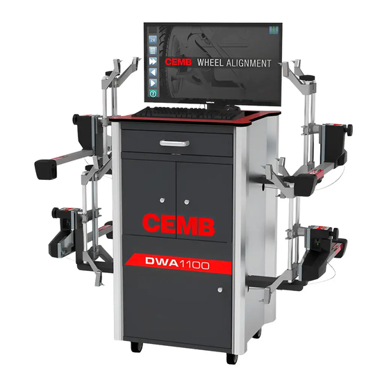
DWA1100
CEMB S.p.A.
Via Risorgimento, 9
23826 Mandello del Lario (LC) ITALY
Telefono: + 39 706369 Fax: + 39 0341 700725
www.cemb.com garage@cemb.com
The Manufacturer declines all liability for any damage to people or property caused by incorrect use of this product.
Subject to change without prior notice.
Advertisement
Table of Contents

Summary of Contents for CEMB DWA1100
- Page 1 Use and maintenance manual DWA1100 CEMB S.p.A. Via Risorgimento, 9 23826 Mandello del Lario (LC) ITALY Telefono: + 39 706369 Fax: + 39 0341 700725 www.cemb.com garage@cemb.com The Manufacturer declines all liability for any damage to people or property caused by incorrect use of this product.
- Page 2 Istruzioni originali Translation of the original instructions Traduction de la notice originale Übersetzung der Originalanweisungen Traducción de las instrucciones originales Tradução das instruções originais...
-
Page 3: Table Of Contents
INSTRUCTIONS FOR USE CONTENTS CAUTION! GENERAL WARNINGS PRECAUTIONS AND INSTRUCTIONS FOR SAFETY, USE AND MAINTENANCE MACHINE DESCRIPTION TECHNICAL DATA COMPONENTS 1 - MACHINE USE 1.1 - BATTERY AND COMMUNICATION STATUS 1.2 - RECHARGING THE BATTERIES 2 - PROGRAM FLOW 2.1 - HOW TO INTERACT WITH THE PROGRAM 3 - PREPARING FOR MEASUREMENT 3.1 - HOME PAGE 3.2 - SETTINGS... - Page 4 13 - MAINTENANCE 13.1 - CLEANING 13.2 - HOW TO ACTIVATE THE DATABANK AND THE SOFTWARE 14 - TROUBLESHOOTING 14.1 - MALFUNCTIONS 14.2 - ALIGNMENT PROBLEMS 15 - STORING AND SCRAPPING 15.1 - STORING 15.2 - SCRAPPING 16 - TESTING THE MEASURING HEADS BY FITTING THEM ON THE VEHICLE 16.1 - MEASUREMENT I –...
-
Page 5: Caution
CAUTION! General warnings ► ▪ The manual refers to the essential requirements set out in the directives, standards and provisions pertaining to use of the machine summarising the most significant points. ▪ In addition to the service instructions, the general rules of law and the binding rules regarding the prevention of accidents and protection of the environment must be observed. -
Page 7: Machine Description
MACHINE DESCRIPTION Technical data ► Power supply and consumption Measuring cabinet Power supply: 230 VAC single-phase 50/60 Hz 115 VAC single-phase on request Max power absorbed: 0,46 kW Max current absorbed: 2 A - 230V 4 A - 115V Measuring heads Internal power supply: 7.2 V rechargeable batteries (Li-Ion) Components... - Page 8 Turntables Plate diameter: 310 mm Capacity: 1000 kg each. 1. Handle 2. Off 3. Plate with non-slip disc 4. Goniometer 5. Reference dial (option only for car) - Premium type turntables. Brake pedal lock This device is used to lock the brake pedal while preparing to make a measurement. Steering lock This device is used to hold the steering wheel in a fixed position;...
-
Page 9: Machine Use
1 - MACHINE USE 1.1 - Battery and communication status ► On some pages battery icons are displayed, which indicate the status of the batteries and the communication between the computer and the measuring heads. FRONT LH FRONT RH REAR RH REAR LH The colour of the battery icons indicates the status of the battery charge: •... -
Page 10: Recharging The Batteries
1.2 - Recharging the batteries ► To recharge the measuring head batteries: 1. Check that the battery power switch is set to (I) 2. Connect the measuring heads to the power cables Recharging is indicated on the screen by the blue battery icons and on the measuring head by the keypad LEDs flashing in sequence and automatically ends after about 5 hours if the battery is completely flat. -
Page 11: Program Flow
2 - PROGRAM FLOW The following flow chart schematizes the typical program flow for a car or truck with only two axles. In case of trucks with more axles certain operations must be repeated. PREPARING FOR Chapter 5 MEASUREMENT VEHICLE Chapter 6 SELECTION SKIP VEHICLE... -
Page 12: How To Interact With The Program
2.1 - How to interact with the program ► The operations indicated by the on-screen keys F1 ... F7 can be performed by clicking on or pressing — on the keyboard or pressing the arrow buttons of the measuring head keypad. On the normal pages: ... -
Page 13: Preparing For Measurement
3 - PREPARING FOR MEASUREMENT 3.1 - Home page ► The home page appears at the beginning of each alignment procedure. From this page you can select: ▪ the car and truck alignment procedure (if enabled) ▪ the measuring mode with 2 or 4 measuring heads. The measuring mode with 2 measuring heads allows measuring and adjusting only the toe-in and camber of the front axle. - Page 14 : switch between the car or the truck procedure : switch between the mode with 2 or 4 measuring heads : menu : settings page : customer databank page : test : calibration ...
-
Page 15: Settings
3.2 - Settings ► To access this page from the home page press and then 3 4 5/6 The following parameters can be set: 1. Time of inactivity after which the measuring heads 12. Settings page password ('ON' = password required go into standby to reduce battery consumption to access the Settings page) (infrared LEDs off). - Page 16 : print settings see below : databank/software activation 13.2 : reset to factory settings : data export setting : saves the settings and exits ¨ : allow selecting and setting the various parameters Print settings ►...
- Page 17 Data export setting ► It is possible to save automatically and daily any single alignment anywhere in the network. Any file contains the complete daily measurements before and after adjustment. How to set it: • Create a new folder where wished to save the data. Any accessible path in the network can be used. •...
-
Page 18: Customer Databank
3.3 - Customer databank ► To access this page from the home page press then . From this page you can search for and display the customer informations and the relative vehicles measurements stored previously. You can search the data by customer name, vehicle license plate, date or work order. -
Page 19: Vehicle Selection
4 - VEHICLE SELECTION 4.1 - Selecting a vehicle ► The Vehicle Selection page allows selecting a vehicle so that during adjustment you can compare the measu- rements with the manufacturer's specifications and display adjustment help images. Select the vehicle first by manufacturer and then by model and sub-model. For faster selection of the model you can display only the models registered as of the year indicated. -
Page 20: Customer Informations
4.2 - Customer informations ► Press to insert customer informations : saves the informations and exits... -
Page 21: Vehicle Specifications
5 - VEHICLE SPECIFICATIONS The "Vehicle Specifications" page allows analysing the manufacturer's specifications to decide which opera- tions are to be performed. In most cases the manufacturer specifies the minimum, standard and maximum values for the main angles: toe-in, camber and caster. Nevertheless, in some cases the manufacturer might: •... -
Page 22: Adjustment Help Images
5.1 - Adjustment help images ► Selecting this option a page is displayed showing the images of the mechanical adjustments that can be made on the vehicle being measured. : displays the next image : goes back to the Vehicle Specifications... -
Page 23: Ride Height
5.2 - Ride height ► To access this page, press from the Vehicle Specifications page The Ride Height page allows: • Viewing which measurements on the vehicle are required by the manufacturer (ride height or inclination of parts of the suspension) and if necessary enter the results. •... -
Page 24: Loads
5.3 - Loads ► To access this page, press from the Vehicle Specifications page. The Loads page allows viewing the loads to be positioned in the vehicle and the amount of fuel there needs to be in the tank as specified by the manufacturer. 1. - Page 25 1. Wheelbases and tracks 2. Manufacturer, model, sub-model or technical name, year of registration of the vehicle (enter in the format 'aaaa - bbbb' 3. Angle values. The first 3 columns indicate: Minimum/standard/maximum or standard/upper tolerance/lower tolerance depending on what was selected with .
-
Page 26: (Truck Only) Axle Configuration
) 5.5 - Axle configuration ► The Axle Configuration page allows configuring the axles of trucks, buses or semi-trailers reference axle You can configure up to 7 axles of which 2 front ones as steering axles and 5 rear axles; the last rear axles can be configured as steering axles. -
Page 27: Fit And Align The Bar On The Fifth Wheel Pin
) 5.6 - Fit and align the bar on the fifth wheel pin ► Only in the case of a semi-trailer, when you go to the next page you are asked to fit the front measuring heads on the fifth wheel pin adaptor. 1. -
Page 28: Runout
6 - RUNOUT The runout phase allows correcting the wheel clamp mounting error. This error is caused by imprecise positioning of the claws or by deformation of the rim or the wheel clamp and is difficult to avoid. Even though there are wheel clamps on the market that are claimed to be "without runout", there is actually no certainty that they sufficiently reduce the error. - Page 29 Scheme to follow to select the most suitable runout method: START START Alignment sensors available ? 3 x 90° LIFTED Is the car lift long enough and the 180° LIFTED vehicle light enough for the runout method on the ground? Are there often wheel steering errors during movement when exe- cuting the runout methods...
-
Page 30: How To Execute Runout
6.1 - How to execute runout ► Starting conditions: • Position the vehicle with the front wheels on the turn plates, the steering wheel straight, the parking brake disengaged and the gear in neutral. • Lock the turn plates and the rear slip plates •... -
Page 31: 180° Or 90° Runout On The Ground
6.2 - 180° or 90° runout on the ground ► 180° 90° 1. Align the steering wheel and position the steering lock 2. Level the measuring heads (green LED) and press on the keypad of any one of the measuring heads 3. - Page 32 HYBRID In the case of runout on the ground, in HYBRID configuration and in CAR measuring mode, before moving the vehicle (step 3), position the rear sensors type TRUCK in the following position: Fasten the rear sensors by tightening the pin locking knob; that way, you prevent the sensor from touching the horizontal plane during backward movement.
-
Page 33: 180° Runout Lifted
6.3 - 180° Runout lifted ► 1. Lift the vehicle so that the wheels are free to turn (you can also lift one wheel at a time) 2. Level all the measuring heads (green LED) 3. Turn a wheel to a reference position, for example, with the handle of the wheel clamp facing down, level the measuring head and press 4. -
Page 34: 3X90° Runout Lifted
6.4 - 3x90° Runout lifted ► Left- hand side wheels Right- hand side wheels 1. Lift the vehicle 2. Turn a wheel to a reference position, for example, with the handle of the wheel clamp facing the rear of the vehicle, level the measuring head and press 3. -
Page 35: Steering
7 - STEERING The steering function allows measuring the characteristic steering angles: caster, SAI, TOOT. It consists of making several measurements with the wheels steered at different steering angles. You can select from three steering modes: • FAST steering: recommended because it is fast to execute •... -
Page 36: Fast Steering
7.1 - FAST steering ► 1. Steer to the left until the word "STOP" appears 2. Without moving the steering wheel, wait for "STOP" to disappear. 3. Steer to the right until the word "STOP" appears again 4. Without moving the steering wheel, wait until "STOP" disappears and a pair of yellow triangles appears 5. -
Page 37: Diagnostics
8 - DIAGNOSTICS The Diagnostics page displays the measurements made on the vehicle before adjustment, next to the data- bank specifications. The measurements out-of-tolerance are displayed in red so that you can easily identify what to adjust. : displays the vehicle dimensions 10.1 ... -
Page 38: Adjustment
9 - ADJUSTMENT During adjustment the wheel angles are continuously measured and displayed so that the effect of the adjustments can immediately be seen. The main angles are shown both in value and in graphic form by an indicator on a green and red scale Tolerances: Minimum Standard... -
Page 39: Adjustment Procedures
9.1 - Adjustment procedures ► The adjustment procedure depends on the type of vehicle, the measuring mode and the manufacturer’s specifications: • Adjustment procedure with two measuring heads 1. Front axle adjustment • Normal car adjustment procedure 1. Rear axle adjustment 2. -
Page 40: Adjusting A Front Axle
Adjust in order the wheel camber and toe-in until the indicator is in the green zone. The thrust angle is can- celled when the toe-in of the wheels is the same. For optimal adjustment, first adjust the camber and then the toe-in If it is difficult to access the adjustment points, you can use the "freezing"... - Page 41 Difference between the right and left values and the maximum permitted value Left front caster Right front caster Right front camber Left front camber Right front toe-in Left front toe-in Total toe-in Steering angle Total toe-in The differences between the right and left camber and caster and the relative tolerances are also displa- yed.
- Page 42 ) Adjustment sequence for the truck procedure: 1. Centre the steering box by turning the steering wheel 2. If nec essary, straighten the steering wheel by acting on the adjuster between the steering box and the steeri wheel without moving the steering box 3.
-
Page 43: (Truck) Adjusting A Rear Axle
) 9.4 - Adjusting a rear axle ► Before the Rear Adjustment page, the Chassis Distance page appears to remind you to adjust the axle with respect to the chassis. 1. Check with a rule and if necessary adjust the distance between the wheels and the chassis so that it is the same for the right and left wheels ... -
Page 44: (Truck) Adjust The Parallelism Between The Two Front Steering Axles
) 9.5 - Adjust the parallelism between the two front steering axles ► In the case of trucks equipped with two front steering axles, at the end of the adjustment procedure you are asked to position the four measuring heads on the two front steering axles to adjust the parallelism between the direction of the first and the second front steering axle. -
Page 45: (Car) Adjusting The Front Toe-In With The Vehicle Resting On A Support
) 9.6 - Adjusting the front toe-in with the vehicle resting on a support ► (toe-in curve -VAS procedure) For vehicles for which the VAS procedure is required, when exiting the Rear Adjustment page, a message is displayed asking you to do some checks on the vehicle. 1. -
Page 46: Adjusting With The Wheels Raised Or Steered (Freezing)
5. Adjust the toe-in by acting on the upper head 6. Press and the following appears: 7. Lift the vehicle, remove the VAS tool, lower the vehicle and settle the suspension 8. Press to go to the Front Adjustment page. 9.7 - Adjusting with the wheels raised or steered (freezing) ►... -
Page 47: Adjustment In Case Of Interruption Of The Infrared Rays
7. Lower the vehicle or straighten the wheels 8. Press to again unfreeze the measurements If you go from the Rear Adjustment page to the Front Adjustment page with the vehicle lifted, for easier operation it is suggested to level the steering wheel and position the steering lock before lifting the vehicle. 9.8 - Adjustment in case of interruption of the infrared rays ►... -
Page 48: Summary
10 - SUMMARY Once you have completed the adjustments, the Summary page appears summarising the measurements before and after adjustment. From this page you can save or print the measurements; modify the customer informations; view the vehicle dimensions and enter the maximum steering measurements Axles whose measurements are displayed ... -
Page 49: Vehicle Dimensions
) 10.1 - Vehicle dimensions ► To access this page from the Summary page press and then The vehicle dimensions are useful to check the symmetry and identify any damage to the suspension system or the chassis. The page displays the thrust angles, axle deviation (set-back), wheelbase and track difference in value and in schematic form. -
Page 50: Wheel Alignment And Measuring Head Levelling
HEEL ALIGNMENT AND MEASURING HEAD LEVELLING In some phases of the alignment procedure, the Alignment and Levelling page may appear asking you to align the wheels and level the measuring heads. Direction in which to steer Measuring head Measuring head level indicators level indicators 1. -
Page 51: Spoiler
12 - SPOILER For some vehicles, especially if fitted with a spoiler, the vehicle body may get in the way of the optical toe-in sensor beam preventing measurement. Beam interrupted In this case, a message appears to warn you that the toe-in sensor beam has been interrupted. In order to, in any case, make the measurement, you can start the Spoiler procedure, which consists of incli- ning the measuring heads that are unable to measure until the optical sensors can see each other. - Page 52 3. Press on the measuring head keypad. The level indicator now shows only the central green LED on, as if the measuring head were horizontal. The following appears: 4. Release the handle and incline the measuring head on the other side of the vehicle (right front) until only the central green LED is shown on then lock the handle.
-
Page 53: Maintenance
13 - MAINTENANCE 13.1 - Cleaning ► • Clean the display with a dry, soft and antistatic cloth; if it is particularly dirty, clean it with a moist cloth and then dry. • Dust the PC keyboard with a soft brush. When not in use, it is advisable to cover the system to protect it against dust. - Page 54 2. Communicate to our customer service the "Machine serial number", the "Databank version", the "Software version" and the sections of the software (car, truck or both) and the groups of databanks for which you wish to obtain the activation code. Example: Databank version: 200801All Machine serial number: 1234-003F...
-
Page 55: Troubleshooting
14 - TROUBLESHOOTING 14.1 - Malfunctions ► The computer does not turn on Check the mains socket and the connections No power supply Press the computer power-on button Display off Turn on the display (button on display) The measuring head does not turn on or turns off unexpectedly Batteries flat Charge the batteries Battery recharging does not start... - Page 56 The keyboard does not work Keyboard disconnected from Check that the keyboard is connected to the computer computer Keyboard language incorrect Set the keyboard language Windows manua The mouse does not work Mouse disconnected from the Check that the mouse is connected to the computer computer The printer does not work The printer is off...
-
Page 57: Alignment Problems
14.2 - Alignment problems ► The steering wheel remains askew • Repeat the measurement executing runout compensation Runout compensation not • If you do not intend to execute runout compensation, executed minimise the runout error by using 3-point wheel clamps or grippers designed to minimise the runout error of 4-point wheel clamps Runout compensation executed... - Page 58 This screen appears Beams interrupted by the Free the visual range of the infrared beams operator getting in the way Activate the procedure that allows you to adjust when Lateral rays interrupted by interposition of an the rays are interrupted irremovable obstacle Execute 3x90 runout Front or rear beams interrupted...
-
Page 59: Storing And Scrapping
15 - STORING AND SCRAPPING 15.1 - Storing ► In the event of long-term storage, disconnect the power supply and protect any parts which may be damaged by excessive accumulation of dust, such as the printer and the display. Grease parts which may be damaged if allowed to dry out. -
Page 60: Testing The Measuring Heads By Fitting Them On The Vehicle
ESTING THE MEASURING HEADS BY FITTING THEM ON THE VEHICLE 16.1 - Measurement I – Toe-in and camber in driving direction ► Position the vehicle in the measuring position but not above the turn plates and the sliding plates. Engage the brake pedal lock. - Page 61 MEASUREMENT SHEET FOR MEASURING HEAD TEST Example: Company: Device no.: Year of construction: Measurement made: Date: MEASUREMENT I COLUMN I MEASUREMENT II COLUMN II COLUMN III COLUMN IV IN DRIVING M e a s u - IN REVERSE M e a s u - Difference DIRECTION r e m e n t...
Need help?
Do you have a question about the DWA1100 and is the answer not in the manual?
Questions and answers