Table of Contents
Advertisement
Quick Links
Advertisement
Table of Contents

Summary of Contents for Sense-Tech Kimax 1
- Page 1 Installation- and Instruction Manual...
-
Page 2: Table Of Contents
Dimensions and technical specifications ................19 Warranty Kimax 1 cabin, trailer and hydraulic are all covered by Sense-Tech Weighing Systems ApS guarantee. Electronic failure and broken components caused by normal use are repaired or exchanged when necessary, when sent to the factory. -
Page 3: How Does It Work
How does it work? The Kimax 1 on board scale is an axle pressure gauge that uses pressure gauging on the air suspension to indicate the load, and to always keep you informed about the present load situation. - Page 4 A dual air inlet can be applied on vehicles with one or more individual axles arranged in a combined level control system. Using a Kimax 1 on two or more individual axles offers you a limited accuracy, because the measuring of the load depends on the center of...
-
Page 5: Air Sensor Installation
Sensor Electrical Additional Introduction Setup Calibration Protection Daily use installation installation information Air sensor installation Connection of compressed air Before you carry out any installation work related to the air suspension, make sure that the suspension has been brought to the lowest possible position and all compressed air is released. First step in the installation is to identify the hose supplying compressed air to the bellows. - Page 6 Air inlet 6 mm Throttle 8 mm Pressure towards Kimax 1 Air pressure for the bellows The Kimax instruments are equipped with push-in fittings. You must make a clean perpendicular cut with a sharp knife or a hose cutter before you connect a new air hose to a Kimax instrument.
- Page 7 Sensor Electrical Additional Introduction Setup Calibration Protection Daily use installation installation information Sensor layout on different vehicles...
-
Page 8: Hydraulic Installation On A Forklift
The hydraulic transmitter should be placed as close to the lifting cylinder as possible to obtain the best measuring accuracy. Setting the Lo calibration point (Kimax 1 Hydraulic) Raise the forks approx. 20 cm from the ground and lower them again approx. 5 cm. -
Page 9: Electrical Installation
For connecting cables use crimp connectors or another approved method. Avoid short-circuiting the system by faulty connections or squeezed cables. Fasten the cables at suitable intervals. Make sure all Kimax 1 instruments are protected with fuses in the supply cables. Pink RS232 TX Data for a printer... - Page 10 Sensor Electrical Additional Introduction Setup Calibration Protection Daily use installation installation information Warning light 0,5 A Brown White Tracker Fuse Switch Key on position Battery Optional: Warning light (A2), Tracker and Kimax printer. Unused wires must be separately isolated.
-
Page 11: Kimax 1 Menu
Sensor Electrical Additional Introduction Setup Calibration Protection Daily use installation installation information Kimax 1 menu Value Press for ~4 secs Value Adjust the value Value Adjust the value Value Adjust the value Value Adjust the value Value Adjust the value... -
Page 12: In Menu
In the Adh menu it is possible to read the input value of the sensor input from when the hi calibration was performed (stored sensor value at loaded calibration). When a hi calibration is performed the Kimax unit automatically saves the in value from the sensor input as an Adh value. Calibration Kimax 1 (example) Calibration... -
Page 13: Calibration
Two reference values are needed to make a correct calibration, one value for an unloaded vehicle (Lo), and one for a loaded vehicle (hi). By means of these two reference values the Kimax 1 Axle Load Indicator will generate a complete pressure chart and display the current axle load on the display. -
Page 14: Alarms
Daily use installation installation information Alarms Calibration Kimax 1 (example) The Kimax 1 has two different alarm functions. When the weight reading exceeds the A1 alarm level, the three digits in the display start flashing. Calibration When the weight reading exceeds the A2... -
Page 15: Protecting Your Calibration
Protecting your calibration Locking your Kimax 1 To lock your Kimax 1 and hereby prevent unintended changes to the calibration, activate at the same time for 5 seconds, while the Kimax is powered. When the display switches off you may release the buttons. Now the display reads -L- and the Kimax is locked. -
Page 16: Daily Use
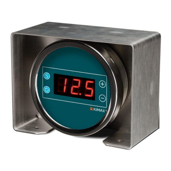
Protection Daily use installation installation information Daily use The Kimax 1 has four buttons and a display with three LED digits. The display is easy to read in a dark cabin and outside in bright sunlight. Plus Save Minus Scroll When the unit starts up it shows tot and after 1 sec. -
Page 17: Serial Output
Serial output The Kimax 1 instrument offers you a RS-232 serial output that broadcasts the measured value, that you read on the display. The string of data is broadcasted every 10 second and can be transmitted to a fleet management vehicle tracker. -
Page 18: Troubleshooting
Sensor Electrical Additional Introduction Setup Calibration Protection Daily use installation installation information Troubleshooting Problem Possible solution Display is flashing like this... The value shown is below zero. Display is flashing like this... When the value on the display exceeds the value for A1 the display starts to flash. -
Page 19: Dimensions And Technical Specifications
Sensor Electrical Additional Introduction Setup Calibration Protection Daily use installation installation information Dimensions and technical specifications Kimax 1 cabin version Air inlet Air inlet* Supply cable * Not present on single air inlet instruments... - Page 20 Air inlet** Air inlet *The Gore-Tex membrane is for venting the Kimax 1 housing, to avoid getting vacuum in the housing during shifting ambient temperatures. The Gore-Tex membrane is only present on the trailer versions of the Kimax 1 instruments.
- Page 21 Air inlet** Air inlet *The Gore-Tex membrane is for venting the Kimax 1 housing, to avoid getting vacuum in the housing during shifting ambient temperatures. The Gore-Tex membrane is only present on the trailer versions of the Kimax 1 instruments.
- Page 22 Introduction Setup Calibration Protection Daily use installation installation information Technical specification Kimax 1 cabin Supply voltage 10 ... 30 Volt direct current Set includes: Kimax 1 cabin 2 sensors Current consumption max. 90 mA Part number 012000-0101 1 x display unit, cabin...
- Page 23 Approval CE and E1 The policy of Sense-Tech Weighing Systems ApS is to continually improve our products. This means that product specifications may change without prior notice. Kimax 1 & Kimax 2 are registered trademarks owned by Sense-Tech Weighing Systems.
- Page 24 Technical file at Sense-Tech Weighing Systems ApS, DK-7173 Vonge Erik Kjærgaard Director Vonge 29. May 2018 Sense-Tech Weighing Systems ApS ● Bygade 43 A ● DK 7173 Vonge ● Tel +45 7670 3001 ● Fax +45 7670 3002 mail@sense-tech.com ● www.sense-tech.com...
Need help?
Do you have a question about the Kimax 1 and is the answer not in the manual?
Questions and answers