
Summary of Contents for Ronde & Schwarz R&S NRP18S Series
- Page 1 ® R&S NRP18S-xx High-Power Three-Path Diode Power Sensors User Manual (;ÜTä2) 1178368602 Version 07...
- Page 2 This manual describes the following high-power three-path diode power sensors with firmware version FW 02.30 and later: ● ® R&S NRP18S-10 (1424.6721K02) ● ® R&S NRP18S-20 (1424.6738K02) ● ® R&S NRP18S-25 (1424.6744K02) © 2022 Rohde & Schwarz GmbH & Co. KG Muehldorfstr.
-
Page 3: Table Of Contents
® Contents R&S NRP18S-xx Contents 1 Safety and regulatory information............7 Safety instructions......................7 Labels on the product....................8 Warning messages in the documentation..............8 2 Welcome....................9 Documentation overview....................9 2.1.1 Getting started manual....................9 2.1.2 User manuals........................9 2.1.3 Tutorials...........................9 2.1.4 Instrument security procedures..................9 2.1.5 Basic safety instructions....................9 2.1.6... - Page 4 ® Contents R&S NRP18S-xx 5 Operating concepts................22 R&S NRP Toolkit......................22 5.1.1 Versions and downloads....................22 5.1.2 System requirements....................22 5.1.3 R&S NRP Toolkit for Windows..................23 Remote control......................24 R&S NRPV........................25 R&S Power Viewer...................... 26 R&S Power Viewer Mobile..................28 R&S NRX........................
- Page 5 ® Contents R&S NRP18S-xx 8.5.5 Configuring the trigger....................54 Configuring results..................... 59 8.6.1 Setting the power unit....................59 8.6.2 Setting the result format....................60 Configuring the measurement modes..............61 8.7.1 Continuous average measurement................61 8.7.2 Burst average measurement..................65 8.7.3 Timeslot measurement....................66 8.7.4 Trace measurement......................
- Page 6 ® Contents R&S NRP18S-xx Trace measurement with synchronization to measurement complete....116 10 Remote control basics...............118 10.1 Remote control interfaces and protocols............... 118 10.1.1 USB interface......................118 10.2 Status reporting system................... 119 10.2.1 Overview........................119 10.2.2 Device status register....................122 10.2.3 Questionable status register..................123 10.2.4 Standard event status and enable register (ESR, ESE)..........
-
Page 7: Safety And Regulatory Information
® Safety and regulatory information R&S NRP18S-xx Safety instructions 1 Safety and regulatory information The product documentation helps you use the product safely and efficiently. Follow the instructions provided here and in the following chapters. Intended use The power sensors are intended for accurate and uncomplicated power measurements in production, R&D and calibration labs as well as for installation and maintenance tasks. -
Page 8: Labels On The Product
® Safety and regulatory information R&S NRP18S-xx Warning messages in the documentation Choosing the operating site Only use the product indoors. The product casing is not waterproof. Observe the ambient conditions such as altitude, operating temperature and climatic loads; see the data sheet. Meaning of safety labels Safety labels on the product warn against potential hazards. -
Page 9: Welcome
® Welcome R&S NRP18S-xx Documentation overview 2 Welcome This chapter provides an overview of the user documentation and an introduction to the R&S NRP18S-xx . 2.1 Documentation overview This section provides an overview of the R&S NRP18S-xx user documentation. Unless specified otherwise, you find the documents on the R&S NRP18S-xx product page at: www.rohde-schwarz.com/product/nrp18s-xx 2.1.1 Getting started manual... -
Page 10: Data Sheets And Brochures
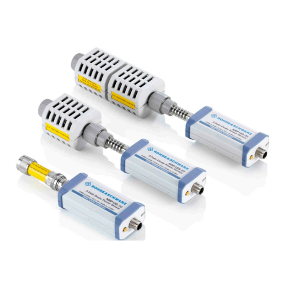
® Welcome R&S NRP18S-xx Key features 2.1.6 Data sheets and brochures The data sheet contains the technical specifications of the R&S NRP18S-xx . It also lists the firmware applications and their order numbers, and optional accessories. The brochure provides an overview of the instrument and deals with the specific char- acteristics. - Page 11 ® Welcome R&S NRP18S-xx Key features Figure 2-1: R&S NRP18S-10, R&S NRP18S-20 and R&S NRP18S-25 (from left) To provide physically correct results, the sensor itself numerically compensates the influence of the attenuator. Hence, the measurement output is not the power level that is measured at the input port of the sensor.
-
Page 12: Preparing For Use
® Preparing for use R&S NRP18S-xx Choosing the operating site 3 Preparing for use Here, you can find basic information about setting up the product for the first time. ● Unpacking and checking..................12 ● Choosing the operating site..................12 ● Considerations for test setup.................. -
Page 13: Considerations For Test Setup
® Preparing for use R&S NRP18S-xx Connecting to a DUT 3.3 Considerations for test setup Give particular attention to the following aspects when handling power sensors. Handling the R&S NRP18S‑xx power sensor ► CAUTION! Hot surfaces. Under certain conditions, the maximum surface tempera- tures of the power sensor can exceed the limits defined in the EN 61010-1 stan- dard, safety requirements for electrical equipment for measurement, control and laboratory use. -
Page 14: Powering The Power Sensor
® Preparing for use R&S NRP18S-xx Powering the power sensor To connect to the DUT 1. Ensure that the RF connector of your DUT is compatible with the RF connector of the power sensor or attenuator. Table 4-1. 2. Inspect both RF connectors carefully. Look for metal particles, contaminants and defects. -
Page 15: Connecting A Cable To The Host Interface
® Preparing for use R&S NRP18S-xx Connecting to a controlling host 3.6 Connecting a cable to the host interface For connecting the power sensor to a USB host, use the host interface. See Chap- ter 4.3, "Host interface", on page 20. Depending on the USB host, use one of the following cables: ●... - Page 16 ® Preparing for use R&S NRP18S-xx Connecting to a controlling host 3.7.1.1 Simple USB connection All R&S NRP18S-xx power sensors can be connected to the USB interface of a com- puter. Required equipment ● R&S NRP18S-xx power sensor ● R&S NRP‑ZKU cable Setup ‑...
- Page 17 ® Preparing for use R&S NRP18S-xx Connecting to a controlling host Required equipment ● 1 to 4 R&S NRP18S-xx power sensors ● 1 R&S NRP‑ZK6 cable per sensor ● R&S NRP‑Z5 sensor hub with external power supply unit and USB cable ●...
-
Page 18: Base Unit
® Preparing for use R&S NRP18S-xx Connecting to a controlling host Set up as shown in Figure 3-2. 1. Connect the R&S NRP‑ZK6 cable to the power sensor. See "To connect a cable to the host interface of the power sensor" on page 15. -
Page 19: Power Sensor Tour
® Power sensor tour R&S NRP18S-xx RF connector 4 Power sensor tour This chapter provides an overview of the available connectors and LEDs of the power sensor. ‑ xx power sensor Figure 4-1: R&S NRP18S 1 = RF connector (attenuator), see Chapter 4.1, "RF connector", on page 19... -
Page 20: Status Information
® Power sensor tour R&S NRP18S-xx Trigger I/O connector ‑ xx RF connector characteristics Table 4-1: R&S NRP18S Power sensor Male connector Matching female con- Tightening torque nector R&S NRP18S 1.36 Nm (12'' lbs) 4.2 Status information The status LED gives information about the state of the power sensor. The following states are defined: Indication State... - Page 21 ® Power sensor tour R&S NRP18S-xx Trigger I/O connector Further information: ● Chapter 8.5.2, "Triggering", on page 46 User Manual 1178.3686.02 ─ 07...
-
Page 22: Operating Concepts
® Operating concepts R&S NRP18S-xx R&S NRP Toolkit 5 Operating concepts For operating the power sensor, you can choose from various possibilities: ● Chapter 5.2, "Remote control", on page 24 ● Chapter 5.3, "R&S NRPV", on page 25 ● Chapter 5.4, "R&S Power Viewer", on page 26 ●... -
Page 23: R&S Nrp Toolkit For Windows
® Operating concepts R&S NRP18S-xx R&S NRP Toolkit ● Microsoft Windows 8/ 8.1 32/64-bit ● Microsoft Windows 10 32/64-bit 5.1.3 R&S NRP Toolkit for Windows The R&S NRP Toolkit installer for Windows-based systems contains the components described in the release notes available at www.rohde-schwarz.com/software/nrp-tool- kit. -
Page 24: Remote Control
® Operating concepts R&S NRP18S-xx Remote control 4. Click "Next" and complete the installation process. 5.1.3.1 Components of the R&S NRP Toolkit Access: "Start" > "NRP-Toolkit" The following tools are part of the R&S NRP Toolkit for Windows. Configure Network Sensor Useful if you have troubles establishing a LAN connection with an R&S NRP LAN power sensor. -
Page 25: R&S Nrpv
® Operating concepts R&S NRP18S-xx R&S NRPV Further information: ● Chapter 8, "Remote control commands", on page 35 ● Chapter 10, "Remote control basics", on page 118 ● Chapter 10.1, "Remote control interfaces and protocols", on page 118 ● Chapter 3.7.1, "Computer", on page 15 5.3 R&S NRPV... -
Page 26: R&S Power Viewer
® Operating concepts R&S NRP18S-xx R&S Power Viewer Connect the power sensor to the signal source. 2. Connect the power sensor to the computer as shown in Figure 5-1. For a detailed description, refer to Chapter 3.7.1.1, "Simple USB connection", on page 16. - Page 27 ® Operating concepts R&S NRP18S-xx R&S Power Viewer Setup Figure 5-2: Setup with the R&S Power Viewer 1 = Signal source 2 = Attenuator 3 = R&S NRP18S-xx power sensor 4 = Host interface connector 5 = R&S NRP‑ZKU cable 6 = USB connector 7 = Computer with installed R&S Power Viewer 1.
-
Page 28: R&S Power Viewer Mobile
® Operating concepts R&S NRP18S-xx R&S NRX 5.5 R&S Power Viewer Mobile The R&S Power Viewer Mobile extends the functionality of the R&S Power Viewer to Android-based devices, such as a smartphone and tablets. For connecting the power sensor to USB-C type mobile phones (Android), use an R&S NRP-ZKC cable. - Page 29 ® Operating concepts R&S NRP18S-xx R&S NRX 5 = R&S NRP‑ZK8 cable 6 = Sensor input connector of the R&S NRX 7 = R&S NRX base unit 1. NOTICE! Incorrectly connecting or disconnecting the power sensor can damage the power sensor or lead to erroneous results. Ensure that you connect or discon- nect the power sensor as described in Chapter 3.4, "Connecting to a DUT",...
-
Page 30: Firmware Update
® Firmware update R&S NRP18S-xx Updating the firmware 6 Firmware update ● Hardware and software requirements..............30 ● Updating the firmware..................... 30 6.1 Hardware and software requirements For performing a firmware update, the system requirements are as follows: ● Connectors and cables for establishing a connection to the computer: Chapter 3.7.1, "Computer", on page 15. - Page 31 ® Firmware update R&S NRP18S-xx Updating the firmware Firmware Update for NRP Family A firmware update can take up to 5 minutes. Ensure that the update is not interrupted. 1. Check the prerequisites. See "Checking the prerequisites" on page 30. 2.
-
Page 32: Using Remote Control
® Firmware update R&S NRP18S-xx Updating the firmware 8. Check if the update was successful. The firmware version in the "Identification" field must match the version you selected in the "Firmware" field. Troubleshooting You do not find the sensor in the list of sensors provided by Firmware Update for NRP Family. - Page 33 ® Firmware update R&S NRP18S-xx Updating the firmware The size of the file is 10242884. This number has 8 digits. Thus, the <block_data> consist of the following: ● ● How many digits follow to specify the file size. ● 10242884 Number that specifies the file size.
-
Page 34: Replacing An R&S Nrp-Zxx With An R&Snrp18S-Xx
® Replacing an R&S NRP‑Zxx with an R&S NRP18S-xx R&S NRP18S-xx Prerequisites 7 Replacing an R&S NRP‑Zxx with an R&S NRP18S-xx The R&S NRP18S-xx power sensors are compatible with the R&S NRP‑Zxx series of power sensors. R&S NRPxx power sensor Replaces R&S NRP‑Zxx power sensor R&S NRP18S-10 R&S NRP-Z22... -
Page 35: Remote Control Commands
® Remote control commands R&S NRP18S-xx Conventions used in SCPI command descriptions 8 Remote control commands In the following, all commands implemented in the sensor are listed according to the command system and then described in detail. Mostly, the notation used complies with SCPI specifications. -
Page 36: Notations
® Remote control commands R&S NRP18S-xx Notations Basic unit Also noted as degrees Angle Percent dBuV DBUV 8.2 Notations For a detailed description of SCPI notations, see Chapter 10, "Remote control basics", on page 118. Numeric suffixes <n> If a command can be applied to multiple instances of an object, e.g. specific sensors, the required instances can be specified by a suffix added to the command. -
Page 37: Common Commands
® Remote control commands R&S NRP18S-xx Common commands Example: Definition: [SENSe<Sensor>:]AVERage:COUNt:AUTO:NSRatio <nsr> Command: AVER:COUN:AUTO:NSR 0.01 Special characters | and { } A vertical bar in parameter definitions indicates alternative possibilities in the sense of "or". The effect of the command differs, depending on which parameter is used. Example: Definition: INITiate:CONTinuous ON | OFF Command INITiate:CONTinuous ON starts the measurements... -
Page 38: Idn
® Remote control commands R&S NRP18S-xx Common commands The command does not alter the ENABle and TRANsition parts of the registers. Usage: Event *ESE <register> Event status enable Sets the event status enable register to the specified value. The query returns the con- tents of the event status enable register in decimal form. -
Page 39: Opt
® Remote control commands R&S NRP18S-xx Common commands *OPC? basically functions like *WAI, but also returns a response. The response is an advantage, because you can query the execution of commands from a controller pro- gram before sending new commands. Thus preventing overflow of the input queue when too many commands are sent that cannot be executed. -
Page 40: Stb
® Remote control commands R&S NRP18S-xx Common commands Setting parameters: <number> Range: 0 to 9 *RST: Usage: Setting only *SRE <register> Service request enable Sets the service request enable register to the specified value. This command deter- mines under which conditions a service request is triggered. Parameters: <register>... -
Page 41: Preparing For The Measurement
® Remote control commands R&S NRP18S-xx Preparing for the measurement Usage: Event 8.4 Preparing for the measurement Before starting a measurement, you need to do the following: ● Selecting the reference source................41 ● Selecting a measurement path................41 ● Selecting a measurement mode................ -
Page 42: Selecting A Measurement Mode
® Remote control commands R&S NRP18S-xx Preparing for the measurement 0 is the most sensitive path. 2 is the most insensitive path. 1 is the path with medium sensitivity. Range: 0 to 2 *RST: [SENSe<Sensor>:]RANGe:AUTO <state> Enables or disables the automatic measurement path selection. Parameters: <state>... -
Page 43: Configuring The Measured Values
® Remote control commands R&S NRP18S-xx Preparing for the measurement "XTIMe:POWer" Trace mode Chapter 8.7.4, "Trace measurement", on page 68. *RST: "POWer:AVG" 8.4.4 Configuring the measured values Before starting a measurement, you can configure the measurand or enable the mea- surement of additional-measured values. -
Page 44: Controlling The Measurement
® Remote control commands R&S NRP18S-xx Controlling the measurement Example: The following sequence of commands configures a peak trace measurement: *RST SENSe:FUNCtion "XTIMe:POWer" SENSe:FREQuency 1.0e9 SENSe:TRACe:POINts 500 SENS:TRAC:TIME 20e-3 TRIGger:SOURce INTernal TRIGger:SLOPe POSitive TRIGger:DTIMe 0.001 TRIGger:HYSTeresis 0.1 TRIGger:LEVel 30e-6 SENSe:TRACe:AVERage:COUNt 8 SENSe:TRACe:AVERage:STATe ON CALCulate:FEED "POWer:PEAK:TRACe"... -
Page 45: Starting And Ending A Measurement
® Remote control commands R&S NRP18S-xx Controlling the measurement 8.5.1 Starting and ending a measurement ..........................45 ABORt ........................45 INITiate:ALL ......................45 INITiate[:IMMediate] ......................45 INITiate:CONTinuous ABORt Immediately interrupts the current measurement. If the measurement has been started as a single measurement (INITiate[:IMMediate]), the power sensor goes into the idle state. -
Page 46: Triggering
® Remote control commands R&S NRP18S-xx Controlling the measurement Ends the continuous measurement mode, and sets the sensor to the idle state. *RST: Example: Chapter 9.3, "Performing a buffered continuous average measurement", on page 113. 8.5.2 Triggering In a basic continuous measurement, the measurement is started immediately after the initiate command, see also Chapter 8.5.2.2, "Waiting for a trigger event",... -
Page 47: Internal
® Remote control commands R&S NRP18S-xx Controlling the measurement Otherwise, as many measurement cycles are performed as determined by the trig- ger count. 8.5.2.3 Trigger sources The possible trigger conditions and the execution of a trigger depend on the selected trigger mode and trigger source. -
Page 48: Controlling The Measurement Results
® Remote control commands R&S NRP18S-xx Controlling the measurement 1 = Dropout time 2 = Trigger hysteresis 3 = Trigger level The RF power between the slots is below the threshold defined by the trigger level and the trigger hysteresis. Therefore, the trigger hysteresis alone cannot prevent triggering at B or at C. -
Page 49: Interplay Of The Controlling Mechanisms
® Remote control commands R&S NRP18S-xx Controlling the measurement Repeating termination control Outputs a measurement result when the entire measurement has been completed. This means that the number of measurement cycle repetitions is equal to the set aver- age count. If the average count is large, the measurement time can be very long. Useful if you expect slow changes in the results, and you want to avoid outputting redundant data. - Page 50 ® Remote control commands R&S NRP18S-xx Controlling the measurement Example: Repeating termination control Further settings for this example: ● [SENSe<Sensor>:]AVERage:TCONtrol REPeat The measurement is started by the trigger event. Due to the chopper phases, one measurement lasts twice the defined aperture time. As defined by the average count, after 4 measurements, the result is averaged and available.
- Page 51 ® Remote control commands R&S NRP18S-xx Controlling the measurement Example: Moving termination control Further settings for this example: ● [SENSe<Sensor>:]AVERage:TCONtrol MOVing ● TRIGger:COUNt Every measurement is started by a trigger event. Due to the chopper phases, one measurement lasts twice the defined aperture time. During each measurement, the trigger synchronization is high (TRIGger:SYNC:STATe ON).
- Page 52 ® Remote control commands R&S NRP18S-xx Controlling the measurement Example: Average count = 1 [SENSe<Sensor>:]AVERage:COUNt For average count 1, the setting of the termination control has no impact. In both cases, the measurement runs for the duration of one aperture time. Then, settled data is available, and the power sensor returns to the idle state.
- Page 53 ® Remote control commands R&S NRP18S-xx Controlling the measurement Example: Moving termination control Further settings for this example: ● [SENSe<Sensor>:]TRACe:AVERage:TCONtrol MOVing Every chopper phase is started by a trigger event and lasts the defined trace time. Dur- ing a chopper phase, the trigger synchronization is high (TRIGger:SYNC:STATe ON).
-
Page 54: Configuring The Trigger
® Remote control commands R&S NRP18S-xx Controlling the measurement 8.5.5 Configuring the trigger Further information: ● Chapter 8.5, "Controlling the measurement", on page 44 Remote commands: ....................54 TRIGger:ATRigger:DELay ..................54 TRIGger:ATRigger:EXECuted? ....................55 TRIGger:ATRigger[:STATe] ......................55 TRIGger:COUNt ....................... 55 TRIGger:DELay ..................... 55 TRIGger:DELay:AUTO ....................... -
Page 55: Chapter 8.5, "Controlling The Measurement
® Remote control commands R&S NRP18S-xx Controlling the measurement TRIGger:ATRigger[:STATe] <state> Controls the automatic trigger function. If enabled, an artificial trigger is generated if the delay time has elapsed after the measurement start and no trigger event has occurred. The delay time is set using TRIGger:ATRigger:DELay. Parameters: <state>... -
Page 56: Trigger:dtime
® Remote control commands R&S NRP18S-xx Controlling the measurement TRIGger:DTIMe <dropout_time> Sets the dropout time for the internal trigger source. During this time, the signal power must exceed (negative trigger slope) or undercut (positive trigger slope) the level defined by the trigger level and trigger hysteresis. At least, this time must elapse before triggering can occur again. -
Page 57: Trigger:immediate
® Remote control commands R&S NRP18S-xx Controlling the measurement Parameters: <hysteresis> Range: 0.00 to 10.00 *RST: 0.00 Default unit: DB TRIGger:IMMediate Causes a generic trigger event. The power sensor leaves the waiting for trigger state immediately, irrespective of the trigger source and the trigger delay, and starts the measurement. -
Page 58: Trigger:sender:state
® Remote control commands R&S NRP18S-xx Controlling the measurement If the power sensor is the trigger sender, it can output its trigger event either on the EXTernal<1> or EXTernal2. If the power sensor triggers itself, the trigger source of the power sensor must be assigned to the other external port, as shown in the examples. -
Page 59: Configuring Results
® Remote control commands R&S NRP18S-xx Configuring results Parameters: <source> HOLD | IMMediate | INTernal | BUS | EXTernal | EXT1 | EXTernal1 | EXT2 | EXTernal2 Chapter 8.5.2.3, "Trigger sources", on page 47. *RST: IMMediate TRIGger:SYNC:PORT <sync_port> Selects the external connection for the sync output of the power sensor. For more information, see TRIGger:SYNC:STATe. -
Page 60: Setting The Result Format
® Remote control commands R&S NRP18S-xx Configuring results 8.6.2 Setting the result format The FORMat subsystem sets the format of numeric data (measured values) that is exchanged between the remote control computer and the power sensors if high-level measurement commands are used. Remote commands: ......................60 FORMat:BORDer... -
Page 61: Configuring The Measurement Modes
® Remote control commands R&S NRP18S-xx Configuring the measurement modes 32 | 64 32-bit or 64-bit If you omit the length, the R&S NRP18S-xx sets the last used length. Example for REAL,32 format: #6768000..<binary float values>..Example for REAL,64 format: #71536000..<binary float values>.. - Page 62 ® Remote control commands R&S NRP18S-xx Configuring the measurement modes Configuring continuous average measurements of modulated signals When measuring modulated signals in continuous average mode, the measurement can show fluctuation due to the modulation. If that is the case, adapt the size of the sampling window exactly to the modulation period to get an optimally stable display.
- Page 63 ® Remote control commands R&S NRP18S-xx Configuring the measurement modes ..............63 [SENSe<Sensor>:][POWer:][AVG:]APERture ............... 63 [SENSe<Sensor>:][POWer:][AVG:]BUFFer:CLEar ............63 [SENSe<Sensor>:][POWer:][AVG:]BUFFer:COUNt? .............. 63 [SENSe<Sensor>:][POWer:][AVG:]BUFFer:DATA? ..............64 [SENSe<Sensor>:][POWer:][AVG:]BUFFer:SIZE ...............64 [SENSe<Sensor>:][POWer:][AVG:]BUFFer:STATe ................64 [SENSe<Sensor>:][POWer:][AVG:]FAST ............65 [SENSe<Sensor>:][POWer:][AVG:]SMOothing:STATe [SENSe<Sensor>:][POWer:][AVG:]APERture <integration_time> Sets the duration of the sampling window in continuous average mode. During this time interval, the average signal power is measured.
- Page 64 ® Remote control commands R&S NRP18S-xx Configuring the measurement modes [SENSe<Sensor>:][POWer:][AVG:]BUFFer:SIZE <count> Sets the size of the result buffer in continuous average mode. You can enable the buffer using [SENSe<Sensor>:][POWer:][AVG:]BUFFer: STATe. Parameters: <count> Range: 1 to 8192 *RST: Example: BUFF:SIZE 1 Chapter 9.3, "Performing a buffered continuous average measurement", on page 113.
-
Page 65: Burst Average Measurement
® Remote control commands R&S NRP18S-xx Configuring the measurement modes [SENSe<Sensor>:][POWer:][AVG:]SMOothing:STATe <state> Enables or disables the smoothing filter, a steep-edge digital lowpass filter. If you can- not adjust the aperture time exactly to the modulation period, the filter reduces result fluctuations caused by modulation. -
Page 66: Timeslot Measurement
® Remote control commands R&S NRP18S-xx Configuring the measurement modes Defining a time interval for the measurement At the beginning and at the end of the measurement interval, you can define time inter- vals that are excluded from the measurement, see Chapter 8.8.3, "Excluding intervals", on page 77. - Page 67 ® Remote control commands R&S NRP18S-xx Configuring the measurement modes Timeslot 1 Timeslot 2 Timeslot 3 Trigger event Trigger level Time Timeslot width Start of fence Length of fence Figure 8-3: Timeslot parameters Triggering a timeslot measurement In timeslot mode, internal and external trigger events from the signal are evaluated depending on the settings of the parameter.
-
Page 68: Trace Measurement
® Remote control commands R&S NRP18S-xx Configuring the measurement modes [SENSe<Sensor>:][POWer:]TSLot[:AVG]:WIDTh <width> Sets the length of the timeslot. See Figure 8-3. Parameters: <width> Range: 10.0e-6 to 0.10 *RST: 1.000e-3 Default unit: Seconds [SENSe<Sensor>:][POWer:]TSLot[:AVG][:EXCLude]:MID:OFFSet[:TIME] <time> Determines the distance from the start of the timeslots to the start of the interval to be blanked out. - Page 69 ® Remote control commands R&S NRP18S-xx Configuring the measurement modes Remote commands: ..............69 [SENSe<Sensor>:]TRACe:AVERage:COUNt ..............69 [SENSe<Sensor>:]TRACe:AVERage:TCONtrol ..............70 [SENSe<Sensor>:]TRACe:AVERage[:STATe] ..................70 [SENSe<Sensor>:]TRACe:DATA? ................72 [SENSe<Sensor>:]TRACe:MPWidth? ................72 [SENSe<Sensor>:]TRACe:OFFSet:TIME ..................72 [SENSe<Sensor>:]TRACe:POINts .................72 [SENSe<Sensor>:]TRACe:REALtime ..................73 [SENSe<Sensor>:]TRACe:TIME [SENSe<Sensor>:]TRACe:AVERage:COUNt <count> Sets the number of readings that are averaged for one measured value. The higher the count, the lower the noise, and the longer it takes to obtain a measured value.
- Page 70 ® Remote control commands R&S NRP18S-xx Configuring the measurement modes [SENSe<Sensor>:]TRACe:AVERage[:STATe] <state> Enables or disables the averaging filter in trace mode. Parameters: <state> *RST: [SENSe<Sensor>:]TRACe:DATA? Returns the measured trace data in a well-defined format. Unlike FETCh<Sensor>[:SCALar][:POWer][:AVG]?, this command takes the set- tings of into account, as explained below.
- Page 71 ® Remote control commands R&S NRP18S-xx Configuring the measurement modes #214THIS IS A TEST<LF> Explanation: 'THIS IS A TEST' has 14 bytes, and '14' has 2 digits, hence the #214 User data content In the further description, the term "user data content" is used for the totality of the con- tained measurement results.
- Page 72 ® Remote control commands R&S NRP18S-xx Configuring the measurement modes Example: TRAC:DATA? Usage: Query only [SENSe<Sensor>:]TRACe:MPWidth? Queries the attainable time resolution in trace mode. The result is the smallest possible distance between two pixels, i.e. it is the smallest time interval that can be assigned to a pixel.
-
Page 73: Configuring Basic Measurement Parameters
® Remote control commands R&S NRP18S-xx Configuring basic measurement parameters [SENSe<Sensor>:]TRACe:TIME <time> Sets the trace length, time to be covered by the trace sequence. This time period is divided into several equal intervals, in which the average power is determined. The number of intervals equals the number of trace points, which is set using [SENSe<Sensor>:]TRACe:POINts. - Page 74 ® Remote control commands R&S NRP18S-xx Configuring basic measurement parameters [SENSe<Sensor>:]AVERage:COUNt:AUTO <state> Sets the mode for determining the average count. Parameters: <state> Auto averaging: the averaging factor is continuously determined and set depending on the power level and other parameters. Fixed filter: the previous, automatically determined averaging factor is used.
- Page 75 ® Remote control commands R&S NRP18S-xx Configuring basic measurement parameters [SENSe<Sensor>:]AVERage:COUNt:AUTO:RESolution <resolution> Defines the number of significant places for linear units and the number of decimal pla- ces for logarithmic units that are likely free of noise in the measurement result. The setting is only considered, if the following applies: ●...
- Page 76 ® Remote control commands R&S NRP18S-xx Configuring basic measurement parameters [SENSe<Sensor>:]AVERage:COUNt:AUTO:TYPE <type> Sets the automatic averaging filter mode. Parameters: <type> RESolution | NSRatio RESolution The usual mode for the power sensors. NSRatio Predefines the compliance to an exactly defined noise compo- nent.
-
Page 77: Setting The Frequency
® Remote control commands R&S NRP18S-xx Configuring basic measurement parameters 8.8.2 Setting the frequency The frequency of the signal to be measured is not automatically determined. For ach- ieving better accuracy, the carrier frequency of the applied signal must be set. [SENSe<Sensor>:]FREQuency <frequency>... -
Page 78: Configuring Corrections
® Remote control commands R&S NRP18S-xx Configuring basic measurement parameters [SENSe<Sensor>:]TIMing:EXCLude:STARt <exclude_start> Available in burst average and timeslot modes. Sets a time interval at the beginning of bursts that is excluded from the measurement. Figure 8-6. Parameters: <exclude_start> Range: 0.0 to 1.0 *RST: Default unit: Seconds [SENSe<Sensor>:]TIMing:EXCLude:STOP <exclude_stop>... -
Page 79: Offset Corrections
® Remote control commands R&S NRP18S-xx Configuring basic measurement parameters Sets the duty cycle for measuring pulse-modulated signals. The duty cycle defines the percentage of one period during which the signal is active. If the duty cycle is enabled, the R&S NRP18S-xx considers this percentage when calculating the signal pulse power from the average power. -
Page 80: S-Parameter Correction
® Remote control commands R&S NRP18S-xx Configuring basic measurement parameters 8.8.4.3 S-parameter correction S-parameter correction compensates for the losses and reflections introduced by a component — such as an attenuator, directional coupler, or matching pad — that is attached to a power sensor. Using S-parameters instead of a fixed offset increases measurement accuracy by accounting for the interaction between the power sensor and the component. - Page 81 ® Remote control commands R&S NRP18S-xx Configuring basic measurement parameters 3. Make sure that the S-parameter settings — selected S-parameter device, S-param- eter correction state — always match the used hardware configuration. 3-Path Diode Power Sensor MHz to GHz, 100 pW to 200 mW (−70 dBm to +23 dBm) SMART SENSOR TECHNOLOGY - port device between signal source and power sensor input Figure 8-7: Operation with 2...
-
Page 82: S-Gamma Corrections
® Remote control commands R&S NRP18S-xx Configuring basic measurement parameters 8.8.4.4 S-gamma corrections Using the complex reflection coefficient, you can determine the power P delivered by the signal source with considerably greater accuracy. The coefficient of the signal source Γ is defined by its magnitude and phase: source ●... -
Page 83: I-Gamma Queries
® Remote control commands R&S NRP18S-xx Configuring basic measurement parameters [SENSe<Sensor>:]SGAMma:CORRection:STATe <state> Enables or disables the use of the complex reflection coefficient to correct the interac- tions of power sensor and signal source. Parameters: <state> *RST: [SENSe<Sensor>:]SGAMma:MAGNitude <magnitude> Sets the magnitude of the complex reflection coefficient of the source, Γ source Parameters: 0.0 ≙... -
Page 84: Using The S-Parameters Program
® Remote control commands R&S NRP18S-xx Configuring basic measurement parameters [SENSe<Sensor>:]IGAMma:PHASe? Queries the phase angle of the complex input reflection coefficient Γ . The result is provided in degrees. Range: -180 degrees to +180 degrees. Example: IGAM:PHAS? Query -1.327654E+02 Response Usage: Query only [SENSe<Sensor>:]IGAMma:EUNCertainty? -
Page 85: Menu Bar
® Remote control commands R&S NRP18S-xx Configuring basic measurement parameters User interface of the S-Parameters program Figure 8-10: S-Parameters dialog Menu bar........................85 └ File........................85 └ Sensor......................86 └ Device......................86 └ Options......................86 └ User Data....................86 └ Remote....................86 └ Show Cal. -
Page 86: Sensor
® Remote control commands R&S NRP18S-xx Configuring basic measurement parameters Sensor ← Menu bar Provides options for loading and saving calibration data directly from or to the sensor, see: ● "To load a calibration data set from a power sensor" on page 88 ●... -
Page 87: Global Flags
® Remote control commands R&S NRP18S-xx Configuring basic measurement parameters Figure 8-11: Example Global Flags Groups the settings for the power sensor behavior regarding S-parameter corrections. S-Parameter Correction ON by Default ← Global Flags If this option is enabled, the S-parameter correction is activated automatically when the sensor is started. -
Page 88: Use Flags In Factory Cal. Data Set
® Remote control commands R&S NRP18S-xx Configuring basic measurement parameters Use Flags in Factory Cal. Data Set ← Global Flags Available if the power sensor supports two different calibration data sets: ● Factory calibration data set containing all factory calibration data. ●... - Page 89 ® Remote control commands R&S NRP18S-xx Configuring basic measurement parameters The "Upload Calibration Data" dialog opens. It shows a list of the available sen- sors. 3. If you cannot find your power sensor in the list, for example because of reconnect- ing the power sensor, you can reload the list by clicking "Rebuild List".
- Page 90 ® Remote control commands R&S NRP18S-xx Configuring basic measurement parameters 6. Create a backup of the calibration data set before making any changes. Select "File" > "Save Calibration Data". A dialog opens where you can select the location to save the calibration data. To change the S-parameter data 1.
- Page 91 ® Remote control commands R&S NRP18S-xx Configuring basic measurement parameters 5. If needed, load uncertainty data. See "To load an uncertainty parameter file" on page 91. 6. Check the entries in the " S-Parameter Device Mnemonic", "Lower Power Limit/W" and "Upper Power Limit/W" fields 7.
- Page 92 ® Remote control commands R&S NRP18S-xx Configuring basic measurement parameters To save the calibration data to the sensor 1. Select "Sensor" > "Save Calibration Data". The "Download Calibration Data" dialog opens. 2. Confirm that the correct power sensor is selected by clicking "Download". After a successful transfer of the data to the power sensor, a confirmation message is displayed.
- Page 93 ® Remote control commands R&S NRP18S-xx Configuring basic measurement parameters ● Option line The option line has the format #[<frequency unit>][<parameter>][<format>][<R n>], where: – Identifies the option line. – <frequency unit> Possible values are Hz, kHz, MHz or GHz. If a frequency unit is not specified, GHz is implicitly assumed.
-
Page 94: Querying Measurement Results
® Remote control commands R&S NRP18S-xx Querying measurement results – <parameter> U must be specified for uncertainty data files. If a parameter is not specified, S is implicitly assumed and as a result an error message is triggered. – <format> This value is ignored in uncertainty measurement files. -
Page 95: Calibrating, Zeroing
® Remote control commands R&S NRP18S-xx Calibrating, zeroing FETCh<Sensor>[:SCALar][:POWer][:AVG]? Queries the last valid measurement result of the measurand that was configured before. To configure the measurand, use before the measurement is initi- CALCulate:FEED ated. Usage: Query only FETCh<Sensor>[:SCALar][:POWer]:BURSt? Queries the last valid measurement result in burst average mode. To configure the measurand, use before the measurement is initi- CALCulate:FEED... - Page 96 ® Remote control commands R&S NRP18S-xx Calibrating, zeroing ......................96 CALibration:DATA ....................96 CALibration:DATA:LENGth? ....................96 CALibration:USER:DATA ..................96 CALibration:USER:DATA:LENGth? ..................97 CALibration<Channel>:ZERO:AUTO CALibration:DATA <caldata> Writes a binary calibration data set in the memory of the power sensor. Parameters: <caldata> <block_data> CALibration:DATA:LENGth? Queries the length in bytes of the calibration data set currently stored in the flash mem- ory.
-
Page 97: Testing
® Remote control commands R&S NRP18S-xx Testing CALibration<Channel>:ZERO:AUTO <state> Performs zero calibration. Turn off all test signals before zeroing. An active test signal during zeroing causes an error. While zero calibration is in progress, no queries or other setting commands are allowed, since the command is synchronous. -
Page 98: Configuring The System
® Remote control commands R&S NRP18S-xx Configuring the system Query parameters: <Item> String Usage: Query only 8.12 Configuring the system The SYSTem subsystem contains a series of commands for general functions that do not directly affect the measurement. 8.12.1 Configuring general functions ...................99 SYSTem:DFPRint<Channel>? .......................99... -
Page 99: System:dfprint
® Remote control commands R&S NRP18S-xx Configuring the system SYSTem:DFPRint<Channel>? Reads the footprint file of the power sensor. Suffix: <Channel> 1...4 Measurement channel if more than one channel is available. Usage: Query only SYSTem:ERRor:ALL? Queries all unread entries in the SCPI communication error queue and removes them from the queue. -
Page 100: System:error:count
® Remote control commands R&S NRP18S-xx Configuring the system SYSTem:ERRor:COUNt? Queries the number of entries in the SCPI communication error queue. Example: SYST:ERR:COUN? Query Response: One error has occurred since the error queue was last read out. Usage: Query only SYSTem:ERRor[:NEXT]? Queries the SCPI communication error queue for the oldest entry and removes it from the queue. -
Page 101: System:help:headers
® Remote control commands R&S NRP18S-xx Configuring the system While a firmware update is in progress, the LED of the power sensor flashes in bright white color. When the firmware update is completed, you can read the result. The result of the query is a readable string. Example: SYST:FWUP:STAT? Query... -
Page 102: System:initialize
® Remote control commands R&S NRP18S-xx Configuring the system Query parameters: <item> "Manufacturer", "Type", "Stock Number", "Serial", "SW Build", "Sensor Name", "Hostname", "IP Address", "Technology", "Func- tion", "MinPower", "MaxPower", "MinFreq", "MaxFreq", "Resolu- tion", "Impedance", "Coupling", "Cal. Due Date", "Cal. Abs.", "Cal. -
Page 103: System:led:mode
® Remote control commands R&S NRP18S-xx Configuring the system Example: SYST:LED:MODE USER Sets the system status LED operating mode to user. SYST:LED:COL #H01a00000 The LED flashes slowly in red. SYSTem:LED:MODE SENSor Sets the system status LED operating mode back to the sensor internal settings. -
Page 104: System:parameters:delta
® Remote control commands R&S NRP18S-xx Configuring the system SYSTem:PARameters:DELTa? Returns an XML-output containing all commands that differ from the defined default status set by on page 39. *RST The commands are accompanied by the same information as for SYSTem: PARameters?. -
Page 105: System:serror:list:all
® Remote control commands R&S NRP18S-xx Configuring the system Static errors occur when you select conflicting settings. For example in timeslot mode, a static error occurs with the following settings: ● Width of a timeslot: 100 µs ● Exclude time at the start of the slot: 40 µs ●... -
Page 106: Using The Status Register
® Remote control commands R&S NRP18S-xx Using the status register Parameters: <update_time> Range: 0.0 to 10.0 *RST: 10e-3 Default unit: Seconds SYSTem:TLEVels? Queries the possible power test levels of the power sensor. Usage: Query only SYSTem:TRANsaction:BEGin Starts a series of settings. Usage: Event SYSTem:TRANsaction:END... -
Page 107: General Status Register Commands
® Remote control commands R&S NRP18S-xx Using the status register ● Chapter 10.2, "Status reporting system", on page 119 Contents: ● General status register commands............... 107 ● Reading the CONDition part................. 107 ● Reading the EVENt part..................108 ● Controlling the ENABle part.................. -
Page 108: Reading The Event Part
® Remote control commands R&S NRP18S-xx Using the status register 8.13.3 Reading the EVENt part STATus:DEVice[:EVENt]? STATus:OPERation:CALibrating[:SUMMary][:EVENt]? STATus:OPERation[:EVENt]? STATus:OPERation:LLFail[:SUMMary][:EVENt]? STATus:OPERation:MEASuring[:SUMMary][:EVENt]? STATus:OPERation:SENSe[:SUMMary][:EVENt]? STATus:OPERation:TRIGger[:SUMMary][:EVENt]? STATus:OPERation:ULFail[:SUMMary][:EVENt]? STATus:QUEStionable:CALibration[:SUMMary][:EVENt]? STATus:QUEStionable[:EVENt]? STATus:QUEStionable:POWer[:SUMMary][:EVENt]? STATus:QUEStionable:WINDow[:SUMMary][:EVENt]? Usage: Query only 8.13.4 Controlling the ENABle part STATus:DEVice:ENABle <value> STATus:OPERation:CALibrating:ENABle <value> STATus:OPERation:ENABle <value> STATus:OPERation:LLFail:ENABle <value>... -
Page 109: Controlling The Positive Transition Part
® Remote control commands R&S NRP18S-xx Using the status register STATus:QUEStionable:POWer:NTRansition <value> STATus:QUEStionable:WINDow:NTRansition <value> Parameters: <value> *RST: 8.13.6 Controlling the positive transition part STATus:DEVice:PTRansition <value> STATus:OPERation:CALibrating:PTRansition <value> STATus:OPERation:PTRansition <value> STATus:OPERation:LLFail:PTRansition <value> STATus:OPERation:MEASuring:PTRansition <value> STATus:OPERation:SENSe:PTRansition <value> STATus:OPERation:TRIGger:PTRansition <value> STATus:OPERation:ULFail:PTRansition <value> STATus:QUEStionable:CALibration:PTRansition <value> STATus:QUEStionable:PTRansition <value>... -
Page 110: Performing Measurement Tasks - Programming Examples
® Performing measurement tasks - programming examples R&S NRP18S-xx Performing the fastest measurement in continuous average mode 9 Performing measurement tasks - program- ming examples If you install the optional software development kit (SDK) of the R&S NRP Toolkit, pro- gramming examples are provided. - Page 111 ® Performing measurement tasks - programming examples R&S NRP18S-xx Performing the fastest measurement in continuous average mode write( '*RST' ) # Enable fast unchopped continuous average measurement write( 'SENS:POW:AVG:FAST ON' ) # Define output format (float) write( 'FORM:DATA REAL,32' ) # Select the trigger condition.
-
Page 112: Triggered Fast Unchopped Continuous Average Measurement
® Performing measurement tasks - programming examples R&S NRP18S-xx Performing the fastest measurement in continuous average mode 9.2.2 Triggered fast unchopped continuous average measurement This example, written in pseudo code, shows how to set up and execute a fast unchop- ped continuous average measurement. -
Page 113: Performing A Buffered Continuous Average Measurement
® Performing measurement tasks - programming examples R&S NRP18S-xx Performing a buffered continuous average measurement # If there is any result in the buffer --> read it if ( query( 'BUFF:COUN?') > 0 ) result = queryBinary( 'BUFF:DATA?' ) numData = numData + result.size # Stop the continuous measurement utilDeviceIO.DeviceWrite( instrument, 'INIT:CONT OFF' ) 9.3 Performing a buffered continuous average measure-... - Page 114 ® Performing measurement tasks - programming examples R&S NRP18S-xx Performing a buffered continuous average measurement // Buffer size is randomly selected to 17 SENSOR.write( "SENS:BUFF:SIZE 17" ); SENSOR.write( "SENS:BUFF:STAT ON" ); SENSOR.write( "TRIG:COUN 17" ); // Read out all errors / Clear error queue SENSOR.query( "SYST:ERR:ALL?", szBuf, sizeof( szBuf ) );...
-
Page 115: Performing Trace Measurements
® Performing measurement tasks - programming examples R&S NRP18S-xx Performing trace measurements 9.4 Performing trace measurements *RST //Set the sensor's operation mode to trace SENSe:FUNCtion "XTIMe:POWer" //Set the carrier frequency SENSe:FREQuency 1.8e9 //Set the number of points for the trace measurement //Using 500 points usually represents a good compromise //between USB transfer speed and resolution SENSe:TRACe:POINTs 500... -
Page 116: Trace Measurement With Synchronization To Measurement Complete
® Performing measurement tasks - programming examples R&S NRP18S-xx Trace measurement with synchronization to measurement complete 9.5 Trace measurement with synchronization to measure- ment complete This example, written in pseudo code, shows how to set up and execute a trace mea- surement using a non-blocking technique. - Page 117 ® Performing measurement tasks - programming examples R&S NRP18S-xx Trace measurement with synchronization to measurement complete // (this loop could also check for cancel-requests from the user or other break conditions) while ( ! bMeasReady ) query( "STAT:OPER:MEAS:EVEN?", &iEvent ); bMeasReady = ((iEvent &...
-
Page 118: Remote Control Basics
® Remote control basics R&S NRP18S-xx Remote control interfaces and protocols 10 Remote control basics For general information on remote control of Rohde & Schwarz products via SCPI, refer to www.rohde-schwarz.com/rc-via-scpi. 10.1 Remote control interfaces and protocols For remote control, communication between the R&S NRP18S-xx power sensors and the controlling host is established based on various interfaces and protocols. -
Page 119: Status Reporting System
® Remote control basics R&S NRP18S-xx Status reporting system USB Resource String The syntax of the used USB resource string is: USB::<vendor ID>::<product ID>::<serial number>[::INSTR] where: ● <vendor ID> is the vendor ID for Rohde & Schwarz (0x0AAD) ● <product ID> is the product ID for the Rohde & Schwarz sensor ●... - Page 120 ® Remote control basics R&S NRP18S-xx Status reporting system Status byte Error queue Device status Questionable status Standard event status RQS/MSS Operation status Message queue Figure 10-1: Status registers overview 1 = Status byte, see Table 10-3 Chapter 10.2.2, "Device status register", on page 122 Chapter 10.2.3, "Questionable status...
- Page 121 ® Remote control basics R&S NRP18S-xx Status reporting system Short description Bit is set if Questionable status register An EVENt bit is set in the QUEStionable status register and summary the associated ENABLe bit is set to 1. A set bit denotes a ques- tionable device status which can be specified in greater detail by querying the questionable status register.
-
Page 122: Device Status Register
® Remote control basics R&S NRP18S-xx Status reporting system 10.2.2 Device status register Sensor error summary Sensor error Sensor error Sensor error Sensor error Legacy locked Reference PLL locked Figure 10-2: Device status register Querying the register: ● STATus:DEVice:CONDition? ● STATus:DEVice[:EVENt]? Querying the static errors: ●... -
Page 123: Questionable Status Register
® Remote control basics R&S NRP18S-xx Status reporting system Bit no. Short description Bit is set if Legacy locked state The power sensor is locked in the NRP legacy mode. Via the SCPI channels (USBTMC or TCP/IP), only query commands can be sent, but no setting commands. - Page 124 ® Remote control basics R&S NRP18S-xx Status reporting system Power summary Calibration summary POST failure Figure 10-3: Questionable status register Querying the register: ● STATus:QUEStionable:CONDition? ● STATus:QUEStionable[:EVENt]? Table 10-5: Used questionable status bits and their meaning Bit no. Short description Bit is set if Power summary Summary of...
- Page 125 ® Remote control basics R&S NRP18S-xx Status reporting system Sensor power Sensor please zero Figure 10-4: Questionable power status register Querying the register: ● STATus:QUEStionable:POWer:CONDition? ● STATus:QUEStionable:POWer[:SUMMary][:EVENt]? Table 10-6: Used questionable power status bits and their meaning Bit no. Short description Bit is set if Sensor power Measurement data of the power sensor is corrupt.
-
Page 126: Standard Event Status And Enable Register (Esr, Ese)
® Remote control basics R&S NRP18S-xx Status reporting system Sensor calibration Figure 10-5: Questionable calibration status register Querying the register: ● STATus:QUEStionable:CALibration:CONDition? ● STATus:QUEStionable:CALibration[:SUMMary][:EVENt]? Table 10-7: Used questionable calibration status bits and their meaning Bit no. Short description Bit is set if Sensor calibration Zeroing of the power sensor was not successful. -
Page 127: Operation Status Register
® Remote control basics R&S NRP18S-xx Status reporting system Operation Complete Query Error Device-Dependent Error Execution Error Command Error User Request Power On Figure 10-6: Standard event status register (ESR) Table 10-8: Used standard event status bits and their meaning Bit no. - Page 128 ® Remote control basics R&S NRP18S-xx Status reporting system Calibrating Measuring Triggering Sense summary Lower limit fail Upper limit fail Figure 10-7: Operation status register Querying the register: ● STATus:OPERation:CONDition? ● STATus:OPERation[:EVENt]? Table 10-9: Used operation status bits and their meaning Bit no.
- Page 129 ® Remote control basics R&S NRP18S-xx Status reporting system Sensor calibrating Figure 10-8: Operation calibrating status register Querying the register: ● STATus:OPERation:CALibrating:CONDition? ● STATus:OPERation:CALibrating[:SUMMary][:EVENt]? Table 10-10: Used operation calibrating status bits and their meaning Bit no. Short description Bit is set if Sensor calibrating Sensor is being calibrated.
- Page 130 ® Remote control basics R&S NRP18S-xx Status reporting system Sensor measuring Figure 10-9: Operation measuring status register Querying the register: ● STATus:OPERation:MEASuring:CONDition? ● STATus:OPERation:MEASuring[:SUMMary][:EVENt]? Table 10-11: Used operation measuring status bits and their meaning Bit no. Short description Bit is set if Sensor measuring Sensor is measuring.
- Page 131 ® Remote control basics R&S NRP18S-xx Status reporting system Sensor waiting for trigger Figure 10-10: Operation trigger status register Querying the register: ● STATus:OPERation:TRIGger:CONDition? ● STATus:OPERation:TRIGger[:SUMMary][:EVENt]? Table 10-12: Used operation trigger status bits and their meaning Bit no. Short description Bit is set if Sensor waiting for trigger Sensor is waiting for a trigger event.
- Page 132 ® Remote control basics R&S NRP18S-xx Status reporting system Sensor initializing Figure 10-11: Operation sense status register Querying the register: ● STATus:OPERation:SENSe:CONDition? ● STATus:OPERation:SENSe[:SUMMary][:EVENt]? Table 10-13: Used operation sense status bits and their meaning Bit no. Short description Bit is set if Sensor initializing Sensor is being initialized.
- Page 133 ® Remote control basics R&S NRP18S-xx Status reporting system Lower limit fail Figure 10-12: Operation lower limit fail status registers Querying the register: ● STATus:OPERation:LLFail:CONDition? ● STATus:OPERation:LLFail[:SUMMary][:EVENt]? Table 10-14: Used operation lower limit fail status bits and their meaning Bit no. Short description Bit is set if Lower limit fail...
- Page 134 ® Remote control basics R&S NRP18S-xx Status reporting system Upper limit fail Figure 10-13: Operation upper limit fail status registers Querying the register: ● STATus:OPERation:ULFail:CONDition? ● STATus:OPERation:ULFail[:SUMMary][:EVENt]? Table 10-15: Used operation upper limit fail status bits and their meaning Bit no. Short description Bit is set if Upper limit fail...
-
Page 135: Troubleshooting
® Troubleshooting R&S NRP18S-xx Problems during a firmware update 11 Troubleshooting ● Displaying status information................135 ● Performing a selftest..................... 135 ● Problems during a firmware update..............135 ● Contacting customer support................136 11.1 Displaying status information Status information is available in several ways. Status LED of the R&S NRP18S-xx The position of the status LED is indicated in Chapter 4, "Power sensor... -
Page 136: Contacting Customer Support
® Troubleshooting R&S NRP18S-xx Contacting customer support 2. If the power sensor is not accessible anymore, contact the service. Firmware update was aborted If there is not enough free storage space, the firmware update is aborted. An error message is displayed, and the status LED of the power sensor starts flashing red. 1. -
Page 137: Transporting
® Transporting R&S NRP18S-xx 12 Transporting Packing Use the original packaging material. It consists of antistatic wrap for electrostatic pro- tection and packing material designed for the product. If you do not have the original packaging, use similar materials that provide the same level of protection. -
Page 138: Maintenance, Storage And Disposal
® Maintenance, storage and disposal R&S NRP18S-xx Regular checks 13 Maintenance, storage and disposal It is advisable to check the nominal data from time to time. 13.1 Regular checks If the power sensor is used frequently, check the RF connectors for visible damage - bent inner conductors, broken contact springs and so on. -
Page 139: Cleaning
® Maintenance, storage and disposal R&S NRP18S-xx Disposal 13.2 Cleaning 1. Disconnect the R&S NRP18S-xx : a) From the DUT. b) From the computer or base unit. 2. Clean the outside of the R&S NRP18S-xx using a lint-free cloth. You can dampen the cloth with water but keep in mind that the casing is not waterproof. - Page 140 ® Maintenance, storage and disposal R&S NRP18S-xx Disposal Rohde & Schwarz has developed a disposal concept for the eco-friendly disposal or recycling of waste material. As a manufacturer, Rohde & Schwarz completely fulfills its obligation to take back and dispose of electrical and electronic waste. Contact your local service representative to dispose of the product.
-
Page 141: List Of Commands
® List of commands R&S NRP18S-xx List of commands [SENSe<Sensor>:][POWer:][AVG:]APERture....................63 [SENSe<Sensor>:][POWer:][AVG:]BUFFer:CLEar..................63 [SENSe<Sensor>:][POWer:][AVG:]BUFFer:COUNt?..................63 [SENSe<Sensor>:][POWer:][AVG:]BUFFer:DATA?..................63 [SENSe<Sensor>:][POWer:][AVG:]BUFFer:SIZE....................64 [SENSe<Sensor>:][POWer:][AVG:]BUFFer:STATe..................64 [SENSe<Sensor>:][POWer:][AVG:]FAST......................64 [SENSe<Sensor>:][POWer:][AVG:]SMOothing:STATe..................65 [SENSe<Sensor>:][POWer:]BURSt:DTOLerance................... 66 [SENSe<Sensor>:][POWer:]BURSt:LENGth?....................66 [SENSe<Sensor>:][POWer:]TSLot[:AVG]:COUNt................... 67 [SENSe<Sensor>:][POWer:]TSLot[:AVG]:WIDTh....................68 [SENSe<Sensor>:][POWer:]TSLot[:AVG][:EXCLude]:MID:OFFSet[:TIME].............68 [SENSe<Sensor>:][POWer:]TSLot[:AVG][:EXCLude]:MID:TIME..............68 [SENSe<Sensor>:][POWer:]TSLot[:AVG][:EXCLude]:MID[:STATe]..............68 [SENSe<Sensor>:]AUXiliary..........................44 [SENSe<Sensor>:]AVERage:COUNt......................73 [SENSe<Sensor>:]AVERage:COUNt:AUTO....................74 [SENSe<Sensor>:]AVERage:COUNt:AUTO:MTIMe..................74 [SENSe<Sensor>:]AVERage:COUNt:AUTO:NSRatio..................74 [SENSe<Sensor>:]AVERage:COUNt:AUTO:RESolution................ - Page 142 ® List of commands R&S NRP18S-xx [SENSe<Sensor>:]TRACe:AVERage:COUNt....................69 [SENSe<Sensor>:]TRACe:AVERage:TCONtrol....................69 [SENSe<Sensor>:]TRACe:AVERage[:STATe]....................70 [SENSe<Sensor>:]TRACe:DATA?........................70 [SENSe<Sensor>:]TRACe:MPWidth?......................72 [SENSe<Sensor>:]TRACe:OFFSet:TIME......................72 [SENSe<Sensor>:]TRACe:POINts........................72 [SENSe<Sensor>:]TRACe:REALtime......................72 [SENSe<Sensor>:]TRACe:TIME........................73 *CLS.................................37 *ESE................................38 *ESR?................................38 *IDN?................................38 *IST?................................38 *OPC................................38 *OPT?................................39 *PRE................................39 *RCL................................39 *RST................................39 *SAV.................................39 *SRE................................40 *STB?................................40 *TRG................................40 *TST?................................40...
- Page 143 ® List of commands R&S NRP18S-xx STATus:OPERation:CALibrating:PTRansition....................109 STATus:OPERation:CALibrating[:SUMMary][:EVENt]?................. 108 STATus:OPERation:CONDition?........................107 STATus:OPERation:ENABle.......................... 108 STATus:OPERation:LLFail:CONDition?......................107 STATus:OPERation:LLFail:ENABle....................... 108 STATus:OPERation:LLFail:NTRansition......................108 STATus:OPERation:LLFail:PTRansition......................109 STATus:OPERation:LLFail[:SUMMary][:EVENt]?..................108 STATus:OPERation:MEASuring:CONDition?....................107 STATus:OPERation:MEASuring:ENABle.......................108 STATus:OPERation:MEASuring:NTRansition....................108 STATus:OPERation:MEASuring:PTRansition....................109 STATus:OPERation:MEASuring[:SUMMary][:EVENt]?..................108 STATus:OPERation:NTRansition........................108 STATus:OPERation:PTRansition........................109 STATus:OPERation:SENSe:CONDition?.......................107 STATus:OPERation:SENSe:ENABle......................108 STATus:OPERation:SENSe:NTRansition...................... 108 STATus:OPERation:SENSe:PTRansition...................... 109 STATus:OPERation:SENSe[:SUMMary][:EVENt]?..................108 STATus:OPERation:TRIGger:CONDition?.....................107 STATus:OPERation:TRIGger:ENABle......................
- Page 144 ® List of commands R&S NRP18S-xx STATus:QUEStionable:WINDow:PTRansition....................109 STATus:QUEStionable:WINDow[:SUMMary][:EVENt]?.................108 STATus:QUEStionable[:EVENt]?........................108 STATus:QUEue[:NEXT]?..........................107 SYSTem:DFPRint<Channel>?.........................99 SYSTem:ERRor:ALL?............................99 SYSTem:ERRor:CODE:ALL?.......................... 99 SYSTem:ERRor:CODE[:NEXT]?........................99 SYSTem:ERRor:COUNt?..........................100 SYSTem:ERRor[:NEXT]?..........................100 SYSTem:FWUPdate............................100 SYSTem:FWUPdate:STATus?........................100 SYSTem:HELP:HEADers?..........................101 SYSTem:HELP:SYNTax:ALL?........................101 SYSTem:HELP:SYNTax?..........................101 SYSTem:INFO?............................. 101 SYSTem:INITialize............................102 SYSTem:LANGuage............................102 SYSTem:LED:COLor............................. 102 SYSTem:LED:MODE............................. 103 SYSTem:MINPower?............................. 103 SYSTem:PARameters:DELTa?........................
- Page 145 ® List of commands R&S NRP18S-xx TRIGger:SENDer:PORT..........................57 TRIGger:SENDer:STATe..........................58 TRIGger:SLOPe...............................58 TRIGger:SOURce............................58 TRIGger:SYNC:PORT............................. 59 TRIGger:SYNC:STATe.............................59 UNIT:POWer..............................59 User Manual 1178.3686.02 ─ 07...
-
Page 146: Index
® Index R&S NRP18S-xx Index Connecting ..............13 Android device Disconnecting ............. 13 R&S Power Viewer Mobile .......... 28 Duty cycle ................78 Application cards ............... 10 Application notes ............... 10 Auto averaging ..............73 Electromagnetic interference (EMI) ........13 Electrostatic discharge (ESD) ........... - Page 147 ® Index R&S NRP18S-xx Measured values Remote control ............43 Measurement R&S NRP Toolkit ............... 22 Burst average ............. 65 Communication program ..........24 Continuous average ............ 61 Components for Windows-based systems ....23 Ending ................. 45 Firmware update ............24 Preparing ..............
- Page 148 ® Index R&S NRP18S-xx Sources Trigger .................47 Special characters Versions of R&S NRP software ......... 24 SCPI ................37 Standard event status register ........126 Status information ............135 Warning message ............... 8 Status LED ................ 20 White papers ..............10 Status register ..............
Need help?
Do you have a question about the R&S NRP18S Series and is the answer not in the manual?
Questions and answers