Table of Contents
Advertisement
Quick Links
Advertisement
Table of Contents

Summary of Contents for DURR NDT CR 35 NDT Plus
- Page 1 CR 35 NDT Plus HD-CR 35 NDT Plus Installation and operating instructions...
- Page 2 The current version of the installation and operating instructions is available in the Download Center: http://q-r.to/CR35NDT...
- Page 3 Contents Contents CR 35 flexible cassette ..NDT plastic cassette ..Stylus ..... Important information Light protection screen .
-
Page 4: Table Of Contents
Contents 11.4 Erasing the image plate ..11.5 Switch off the unit... . 12 Cleaning ......12.1 Image plate scanner . - Page 5 These installation and operating instructions CE labelling apply to: CR 35 NDT Order number: 2134-000-60 Conformity mark for the United Kingdom HD-CR 35 NDT Plus of Great Britain and Northern Ireland Order number: 2134-000-61 Manufacturer Warnings and symbols Warnings Date of manufacture...
- Page 6 Important information Warning – dangerous high voltage Warning - laser beam Lower and upper temperature limits Upper temperature limit Keep dry Fig. 2: Warning – laser beams This way up / store and transport in an Information about the laser upright position source Fragile, handle with care...
- Page 7 Important information Safety The Installation and Operating Instructions ❯ must be accessible to all operators of the unit Dürr NDT has designed and constructed this unit at all times. so that when used in accordance with its Inten- ded Use there is no danger to people or prop- Specialist personnel erty.
- Page 8 Important information Transport The original packaging provides optimum protec- tion for the unit during transport. Original packing for this unit can be ordered from DÜRR NDT as required. DÜRR NDT does not accept liability for any damage to the unit resulting from transport in unsuitable packaging, even during the guarantee period.
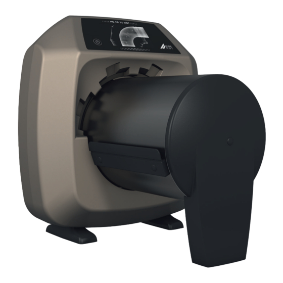
- Page 9 Product description Product description Overview CR 35 NDT Plus / HD-CR 35 NDT Plus Mains cable Image Plate Scanner Power supply unit Image plate Light protection screen CR 35 Image plate cassette (mounted on device) SDHC memory card NDT plastic cassette...
- Page 10 – HD-IP Plus image plate 10x24 cm CR 35 NDT Plus – HD-IP Plus image plate 10x48 cm image plate scanner ....2134-60 –...
- Page 11 Product description D-Tect Viewer ....2134-725-09 Consumables D-Tect measuring tool (wall thick- The following materials are consumed during ness and corrosion) ... . 2134-725-10 operation of the device and must be reordered D-Tect PT Tool .
- Page 12 Product description HD-IP Plus image plate GCR image plate 6x48 cm (1 piece) ... . . HDIP0648108 10x48 cm (1 piece) ... GP1048CM113 HD-IP Plus image plate GCR image plate 10x24 cm (1 piece) .
- Page 13 Laser class (unit) In accordance with IEC 60825-1:2007 Laser source Laser class In accordance with IEC 60825-1:2007 Wavelength l Output ≤ 15 Laser source HD-CR 35 NDT Plus Laser class in accordance with EN 60825-1:2007 Wavelength l Output Noise level Standby dB(A)
- Page 14 Product description General technical data Max. feeding width for image plates 35.4 13.9 Heat output < 140 Degree of soiling Duty cycle S2 (in accordance with VDE 0530-1) Duty cycle S6 (in accordance with VDE 0530-1) Max. noise level db(A) <...
- Page 15 Scan mode name: 100µm White IP - Binning Pixel size μm Native laser spot μm Laser Laser level 3000 Pixel binning HD-CR 35 NDT Plus (TreFoc) Scan mode name: BAM Certified Mode (15/15/30) Pixel size μm Native laser spot μm 12.5 Laser Laser level...
- Page 16 Product description Scan mode name: BAM Certified Mode (15/15/30) 2114 Pixel binning Basic local resolution μm Scan mode name: 25µm White IP - Binning Pixel size μm Native laser spot μm 12.5 Laser Laser level 2114 Pixel binning Scan mode name: 25µm Blue IP / High Res White IP Pixel size μm Native laser spot...
- Page 17 Product description Scan mode name: 100µm White IP - Binning Laser Laser level 4000 Pixel binning 9000-608-130/02 2206V004...
- Page 18 Product description Simplified declaration of con- Type plate formity The type plate is located on the rear side of the foot. WLAN stick A WLAN stick from a third-party manufacturer is installed in the unit; this stick complies with Directive 2014/53/EU, among others. Which WLAN stick is installed can be found directly on the WLAN stick.
- Page 19 Product description Operation If a scanning task is started via the imaging soft- ware, the image is automatically transmitted to the computer. Image plate scanner If a scanning task is started via the touch screen, the image is saved to the memory card and then needs to be transferred to the computer.
- Page 20 Product description Image plate The image plate stores X-ray energy, which is re- emitted in the form of light after excitation via the laser. This light is then converted to image infor- mation in the image plate scanner. The image plate has an active side and an inac- tive side.
- Page 21 Product description Additionally, the light protection cover with its NDT plastic cassette adhesive strips makes it easier to insert the image plate for scanning. Information on handling can be found in leaflet 9000--608-58. The light protection cover is a disposable item. CR 35 image plate cassette The plastic cassette can be inserted into stand- ard X-ray cassette trays.
- Page 22 Assembly Installation Assembly Carrying the unit The installation, connection and commis- NOTICE sioning of the device may only be per- Risk of damage to sensitive compo- formed by qualified specialists or persons nents in the unit as a result of shocks trained by DÜRR NDT.
- Page 23 Assembly Setting up the unit Removing the protective film from the touch screen Portable and mobile HF communication applian- ces can interfere with the effectiveness of electri- Grasp one corner of the protective touch ❯ cal devices. screen film and peel it off carefully. Do not stack the unit next to or together with ❯...
- Page 24 Assembly Check whether the memory card has been Electrical connections ❯ inserted in the unit correctly. If the memory Safety when making electrical connections card has been inserted in the unit incorrectly, take it out again and re-insert it properly. The unit must only be connected to a correctly ❯...
- Page 25 Assembly Connecting the device to the Connecting the unit via the network cable Connect the supplied network cable to the net- network ❯ work connection of the device. Purpose of the network connection The network connection is used to exchange information or control signals between the unit and a software installed on a computer, in order to, e.
- Page 26 Assembly Commissioning Port Purpose Service 2005 TCP, Diagnosis Telnet, NOTICE 23 TCP Short circuit due to the build up of condensation The port can vary depending on the con- Do not switch on the unit until it has ❯ figuration. warmed up to room temperature and it is dry.
- Page 27 Assembly Click on Apply. Configuring the unit in D-Tect ❯ The configuration is saved. Configuring is carried out using CRNetConfig, which is automatically installed on installation of Testing the device D-Tect. You can scan in an X-ray image to check that the Select Start >...
- Page 28 Assembly Entering a permanent IP address (recommen- Electrical safety checks ded) Carry out the necessary electrical safety check- ❯ ing in accordance with national law (e.g. hous- To reset the network settings, keep the ing leakage current). unit reset key pressed for 15 - 20 sec- Document the results.
- Page 29 Usage Using menus Usage The menus integrated in the main window con- tain additional commands, which can be selec- ted as required. Operating the touch To open the menu, touch ❯ screen NOTICE Damage to the touch screen due to incorrect handling Only operate the touch screen using ❯...
- Page 30 Usage 10 Correct use of image Calling up messages on the touch screen plates The Messages view shows an overview of all Image plates are flexible like X-ray film. How- ❯ previous messages. Here, the messages are divi- ever, the image plates should not be bent. ded into the following categories: Fault Unit will no longer function.
- Page 31 Usage 11 Operation Clean image plates properly (see "12.2 Image ❯ plate"). CAUTION The image data on the image plate is not permanent. The image data is altered by light, natu- ral X-ray radiation and scattered X-ray radiation. This will lead to a reduction in diagnostic information and clarity.
- Page 32 Usage X-ray with CR 35 image plate cassette X-ray without CR 35 image plate cassette Slide the image plate completely into the CR Slide the image plate directly into the CR 35 ❯ ❯ 35 image plate cassette. The black (inactive) flexible cassette or the light protection cover.
- Page 33 Usage 11.2 Scanning the image data via Where the image plate is used without the a computer CR 35 image plate cassette, then it must not be removed from the CR 35 flexible Starting the image plate scanner and soft- cassette/light protection cover and placed ware aside.
- Page 34 Usage Click Start. ❯ CAUTION The touch screen will display an animated vis- ual symbol requesting insertion of the image Loss of image data caused by light plate. entering the device Do not remove the CR 35 image plate Only insert the image plate when the ❯...
- Page 35 Usage X-ray without CR 35 image plate cassette Place the CR 35 flexible cassette/light protec- ❯ tion cover together with the image plate into Open the CR 35 flexible cassette/light protec- ❯ the unit until the image plate is automatically tion cover.
- Page 36 Usage 11.3 Scanning image data via the Select image settings and scan mode (see ❯ "4.3 Scanning modes"). touch screen on the unit The touch screen will display an animated visual symbol requesting insertion of the Starting the image plate scanner image plate.
- Page 37 Usage Scanning the image plate CAUTION X-ray with CR 35 image plate cassette Loss of image data caused by light Remove the CR 35 image plate cassette from ❯ entering the device the X-ray cassette. Do not remove the CR 35 image plate ❯...
- Page 38 Usage X-ray without CR 35 image plate cassette Place the CR 35 flexible cassette/light protec- ❯ tion cover together with the image plate into Open the CR 35 flexible cassette/light protec- ❯ the unit until the image plate is automatically tion cover.
-
Page 39: Erasing The Image Plate
Usage 12 Cleaning 11.4 Erasing the image plate The image data is automatically erased after scanning. NOTICE If you do not want the image data to be erased, The use of unsuitable agents and this function can be disabled for the current methods can damage the unit and scanning process by selecting Disable erasing accessories. -
Page 40: Image Plate Cassette, Flexible Cassette, Plastic Cassette
Usage Remove resistant or dried on dirt with the 12.3 Image plate cassette, flexible ❯ image plate cleaning wipe. When doing this, cassette, plastic cassette follow the instructions for use for the cleaning When dirty, the surfaces must be cleaned. wipe. -
Page 41: Maintenance
Usage 13 Maintenance 13.1 Recommended maintenance schedule Only specialist staff or personnel trained by DÜRR NDT may maintain the appliance. Prior to working on the unit or in case of danger, disconnect it from the mains. The recommended maintenance intervals are based on operating the appliance 220 working days per year. -
Page 42: Troubleshooting
Troubleshooting Troubleshooting 14 Tips for operators and service technicians Any repairs exceeding routine maintenance may only be carried out by qualified personnel or our service. Prior to working on the unit or in case of danger, disconnect it from the mains. 14.1 Poor X-ray image Error... - Page 43 Troubleshooting Error Possible cause Remedy X-ray image is mirror-inverted Image plate not inserted straight Insert image plate correctly. ❯ in foil cassette or light protection cover. Image plate not placed straight. Position the image plate cor- ❯ rectly. Ghosting or double exposure Image plate exposed twice Only expose the image plate ❯...
-
Page 44: Software Error
Troubleshooting Error Possible cause Remedy Light strips in the scanning Too much incident ambient light Darken the room. ❯ during the scanning process window Turn the unit so that the light ❯ does not fall directly onto the input unit. Horizontal, grey lines on the Transport slipping Clean the transport mecha-... - Page 45 Troubleshooting Error Possible cause Remedy Imaging software does not Unit not switched on Switch on the unit. ❯ recognise the unit Connecting cable between Check the connecting cable. ❯ device and computer not cor- rectly connected Computer does not detect any Check the connecting cable.
-
Page 46: Fault On The Unit
Troubleshooting 14.3 Fault on the unit Error Possible cause Remedy Unit does not switch on No mains voltage Check the mains cable and ❯ plug connection and replace if necessary. Check the power supply unit. ❯ If the touch screen does not ❯... - Page 47 Troubleshooting Error Possible cause Remedy Network connection has been WLAN stick not inserted Insert the WLAN stick into the ❯ unit. disconnected Distance to WLAN router too Set up the unit closer to the ❯ great WLAN router. Walls between WLAN router and Set up the unit closer to the ❯...
-
Page 48: Error Messages On The Touch Screen
Troubleshooting 14.4 Error messages on the touch screen Error Possible cause Remedy Error code -1008 Internal connection interrupted Update the firmware. ❯ Temperature of unit too high Allow the unit to cool down. Error code 1010 ❯ Inform a Service Technician. ❯... - Page 49 Troubleshooting Error Possible cause Remedy Error code 1172 Radiation deflector assembly or Switch the device off and on. ❯ the SOL sensor defect Inform a Service Technician. ❯ Replace the radiation deflec- ❯ tor assembly. Error code 10000 Unit exposed to too much light Darken the room.
-
Page 50: Appendix
Appendix Appendix 15 Settings menu layout Device data Device information Dealer information Report Operator Access level Administrator Service Technician In-house technician 9000-608-130/02 2206V004... - Page 51 Appendix Language German (DE) System settings English (EN) Date & time Date Time Network MAC address Name Interface WLAN DHCP IP address Subnet mask Gateway Acquisition settings Project number Genus project Subtitle Test date Comment X-ray parameters Acquisition type Weld / solder seam Casting / cast metal piece Touch screen...
- Page 52 Appendix Test Service menu Scanning mode Display scanning modes Edit scanning modes Maintenance Reset maintenance interval Messages Diagnosis Statistics Manipulation Transport Insert Erasure unit Pentaprism Query sensor values Sensors Temperatures Internal device voltages Oscilloscope Check touch screen Display test images Factory settings Reset scanning modes Visible from access level Operator or higher...
-
Page 53: Scanning Times
Appendix 16 Scanning times The scanning time corresponds to the time taken for complete scanning of image data and depends on image plate format and pixel size. The time to image will depend largely on the computer system used and its work load. Times stated are approximate. -
Page 54: File Sizes (Uncompressed)
Appendix 17 File sizes (uncompressed) The actual file size will depend on the image plate format and the pixel size. File sizes stated are approx- imate and have been rounded upwards. Suitable compression methods can considerably reduce the file size without loss of data. Scan mode name BAM Certified 25µm Blue IP /... - Page 56 Hersteller / Manufacturer: DÜRR NDT GmbH & Co. KG Höpfigheimer Str. 22 74321 Bietigheim-Bissingen Germany Fon: +49 7142 99381-0 www.duerr-ndt.com info@duerr-ndt.com...
Need help?
Do you have a question about the CR 35 NDT Plus and is the answer not in the manual?
Questions and answers