
Subscribe to Our Youtube Channel
Related Manuals for Stack ST500


Summary of Contents for Stack ST500
- Page 1 Quartz Quartz kRPM kRPM Model ST500 Tach-Timer 542047-003...
- Page 2 IMPORTANT The Tach-Timer is supplied with its Demonstration Mode active. Connecting power will start the Demonstration Mode. Change the Cylinders setting to disable the Demonstration Mode (see page 46)
- Page 3 Install the Tach-Timer and connect it to the switched battery circuit, e.g. Ignition (B+) and battery negative (B-). Install and connect the controls (follow the instructions starting on page 11). Connect the Tach-Timer ‘ES’ wire to the ignition low tension circuit. Connect any additional sensors supplied.
-
Page 5: Table Of Contents
ST500 Tach-Timer CONTENTS 3 ................INTRODUCTION 5 ..............How to use this manual 5 ..................Safety Issues 6 ..............Unpacking and Inspection 7 ................INSTALLATION 7 ................Product Installation 7 ................. Instrument Panel 8 ..................Wiring Harness 10 ................Tach–Timer Display 11 .................... - Page 6 ST500 Tach-Timer 29 ................Lap and Split Times 31 ................Manual Split Setup 32 ...............Automatic Split Setup 35 ......MEMORY REVIEW AND SYSTEM SETUP 35 ..............Memory review features 38 ..................Setup mode 48 ................... TESTING 50 ................MAINTENANCE 50 ................. Troubleshooting 59 ..............
-
Page 7: Introduction
ST500 Tach-Timer Introduction INTRODUCTION Thank you for selecting the Stack Tach–Timer as your choice of vehicle’s instrumentation – we feel sure that you are going to be delighted by your purchase! The Tach–Timer is a superb quality instrument that integrates a number of performance functions into a single display product. - Page 8 For Tach–Timers that include a speed and odometer display, you will also require a Stack ST670 or ST669 wheel speed sensor. If your Tach–Timer includes the option to trigger lap times automatically, you will also require a vehicle-mounted infra-red (IR) sensor and a track- side IR beacon.
-
Page 9: How To Use This Manual
The wiring harness supplied with the Tach–Timer is certified for • use in high temperature applications up to 105°C. Do not substitute wires that have a lower temperature rating than this. Contact Stack © Stack Limited... -
Page 10: Unpacking And Inspection
• Use suitable glands or grommets to protect the wiring harness where • it passes through vehicle bulkheads or panels. Unpacking and Inspection When you unpack your ST500 Tach–Timer, check all the items against the packing list. © Stack Limited... -
Page 11: Installation
ST500 Tach-Timer Installation INSTALLATION You do not need complicated tools or special training to install the Tach– Timer. To gain the benefits of using this quality instrument all you need are a few basic workshop tools, the willingness to read and follow these instructions carefully and the time to complete each task in sequence. -
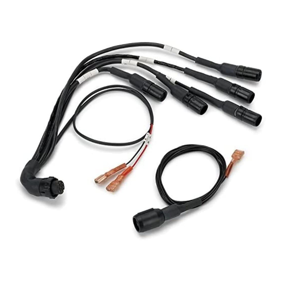
Page 12: Wiring Harness
80 mm diameter hole. Wiring Harness Stack supplies a wiring harness to connect the Tach–Timer within the vehicle. If you find that the standard wiring harness is unsuitable for installation on your vehicle, contact Stack for details of wiring harness extensions. - Page 13 ST500 Tach-Timer Installation Figure 3 - Electrical connections © Stack Limited...
-
Page 14: Tach-Timer Display
Installation ST500 Tach-Timer 3 Note that your installation may not use all the cables in the harness. You should tie back and protect all unused connectors. 4 Begin at the instrument panel where you will install the Tach–Timer. Lay the wiring... -
Page 15: Controls
ST500 Tach-Timer Installation into the incorrect port. Tighten the locking collar by hand. The sec- ond, 6-way, port allows you to connect the optional additional shift light. Fit the Tach–Timer into the instrument panel using the supplied O- ring. Reach behind the instrument panel and position the securing bracket as shown in Figure 4. -
Page 16: Engine Speed Measurement
To measure engine speed you must make the correct connections between the Tach–Timer and the vehicle ignition system. Contact Stack for advice if you have a complicated ignition system. Ignition System... - Page 17 ST500 Tach-Timer Installation Electronic ignition connection Connect to the electronic ignition of the vehicle as indicated in Figure 6. If your Tach–Timer includes the Lap Timing sensor, the Wheel Speed sensor or the external shift light follow the instructions below to install them.
-
Page 18: Lap Timing Sensor (Optional)
Lap Timing Sensor (optional) The lap-timing sensor triggers the Tach–Timer automatically each time the vehicle passes the Stack infra-red (IR) beacon at the side of the track. Choose a location on the vehicle for the lap-timing sensor: • You must position the sensor to be horizontal and square to the vehicle axis. - Page 19 ST500 Tach-Timer Installation period after it senses the first beacon. This ‘lap masking’ feature prevents multiple triggering within each lap. Attach the wire labelled ‘LAP’ of the harness to the sensor at the 4- way ‘Sure-Seal’ connector. Take care to assemble this connector in the correct orientation.
-
Page 20: Trackside I.r. Beacon (Optional)
Installation ST500 Tach-Timer Trackside I.R. Beacon (optional) There must be only one Stack trackside beacon used on the track. Do not place your beacon half way around the track because this may inconvenience other users of Stack equipment. If you have fitted the optional lap timing sensor to your vehicle, you will need to use the trackside IR beacon to trigger the sensor for each lap. -
Page 21: Manual Lap Timing (Optional)
ST500 Tach-Timer Installation • Protect both transmitter lenses of the beacon from water spray. During wet conditions, fit a protective shroud over the beacon. You must supply the beacon with power from a convenient 12V DC source. A sealed lead-acid battery with a rating of at least 2.5 Ah is ideal for this purpose. -
Page 22: Wheel Speed Sensor (Optional)
Furthermore, because split timing also comes directly from the lap timing input, any errors in the lap timing will degrade the accuracy of split times. For these reasons, Stack does not recommend the use of manual lap timing. - Page 23 ST500 Tach-Timer Installation not try to use these as targets. If possible, choose a wheel that ex- • periences negligible wheel spin, lift or lock-up – for example, an undriven wheel. Ideally, the targets should be • equally spaced around the wheel...
-
Page 24: External Shift Light (Optional)
Before you install an external shift light, you should note the following: • Select a location for the shift light that the driver can see easily. • Stack can supply an external shift light that you can connect di- rectly to the Tach–Timer. You can also request a special shrouded version that you can mount on top of the dashboard to be in the direct line of sight for the driver. -
Page 25: Battery Connection
ST500 Tach-Timer Installation Drill a hole or install a bracket to support the external light in the location you have selected. Connect the light to the 6-way connector on the Tach–Timer. Battery connection The Tach–Timer accepts power from the vehicle electrical system through the two cables labelled ‘B+’... -
Page 26: Operation
Operation ST500 Tach-Timer OPERATION This section of the manual tells you how to use the Tach–Timer. You can access all the Tach–Timer functions by using the Driver button and the rotary control. This simple but effective method of operation allows the driver to operate the system with minimal distraction. - Page 27 ST500 Tach-Timer Operation Turn rotary control in Memory review and Setup mode to cycle • through menu options In Setup mode - Adjust parameter • • In Lap memory mode - Cycle through lap and split times Press and turn...
-
Page 28: Power-On The Tach-Timer
Operation ST500 Tach-Timer Normal mode is the normal operating condition of the Tach–Timer. • In this condition the Tach–Timer provides all available measurements and functions for the driver. Setup mode allows you to configure the Tach–Timer for your • specific vehicle and driver requirements. -
Page 29: Changing The Display Layers
If none of these indications appears when you power-on the system, consult the troubleshooting instructions near the end of this user guide. Contact Stack for advice if necessary. Changing the display layers With the Tach–Timer operating in its ‘normal’ mode, you will see a display similar to that shown in Figure 10. - Page 30 Operation ST500 Tach-Timer Display Layer 2 The display includes the odometer only on the ST500SR Tach-Timer. It is optional on other models. Layer 2 shows the odometer reading and the vehicle speed. On models that do not have the odometer option available, the odometer part of the display will be blank.
- Page 31 ST500 Tach-Timer Operation Display Layer 4 The Corner Speed function is standard on the ST500P and M. Optional on other models. Layer 4 shows the minimum Corner Speed. This is the latest value trapped by the Tach–Timer for the minimum speed reached while cornering.
- Page 32 Operation ST500 Tach-Timer Lap time (always enabled) M:SS.ss Or M:SS.s if time longer than 10 minutes Split time (if enabled) Acceleration (if enabled) Standing quarter mile (if enabled) Battery alarm Lap memory has fewer than 20 spaces remaining Lap memory is full...
-
Page 33: Lap And Split Times
The driver presses the Driver button to cancel the pop-up message and return to the normal driver display. Lap and Split Times The lap timing feature of the ST500 Tach–Timer allows you to measure the following: • Total time to complete each lap •... - Page 34 Operation ST500 Tach-Timer When the vehicle passes the beacon (or when the driver presses the Lap Timer button) again, the Tach–Timer displays the total time for the completed lap in a pop-up message. Simultaneously, it resets the timer to zero and starts to time the next lap.
-
Page 35: Manual Split Setup
ST500 Tach-Timer Operation distances manually, or you can set them automatically as you drive the vehicle around the track. After you configure the Tach–Timer with split distances, it will start to measure distance around the track until it passes the S1 reference point. -
Page 36: Automatic Split Setup
Operation ST500 Tach-Timer and turn the control simultaneously to set the first split distance. Release the rotary control and then turn it clockwise one step until the display shows the Split 2 distance. Press and turn the control to set the second split distance. - Page 37 ST500 Tach-Timer Operation display change: The distance shown continues to increase as the vehicle moves, until the driver presses the Driver button again to mark the second Split distance marker. This procedure sets both split marker distances in the Setup Menu. You can follow the instructions to set the split distances manually if you need to adjust them.
- Page 38 Operation ST500 Tach-Timer vehicle is already moving, the Tach–Timer will wait for the speed to be zero. You will still require a beacon at the top of the hill to give the end time. © Stack Limited...
-
Page 39: Memory Review And System Setup
ST500 Tach-Timer Memory review MEMORY REVIEW AND SYSTEM SETUP Press the rotary control for longer than one second, then release it to enter the Memory review and Setup mode. Whatever the engine speed, the tachometer needle will be placed •... - Page 40 Memory review ST500 Tach-Timer Press and turn the rotary control to cycle through the lap memory, turning the control anticlockwise to review earlier laps. The Tach–Timer can record lap and split times for up to 75 laps before the lap memory becomes full.
- Page 41 ST500 Tach-Timer Memory review Standing quarter mile timer review – Standard feature on ST500SR. Optional on other models. The display shows the time that it took to cover a quarter mile from a standing start. The timer will be triggered automatically each time the vehicle starts moving.
-
Page 42: Setup Mode
Setup ST500 Tach-Timer Setup mode In the Setup mode, if you press the Driver button as you press and turn the rotary control, you will change some of the parameters in larger steps. Standard feature on all models. Press and hold the rotary control for longer than one second to reset all the peak values. - Page 43 ST500 Tach-Timer Setup Use the rotary control to set the vehicle speed that triggers the start of the acceleration timing. You can use the Setup mode to set the speed units to MPH or km/h. Use the rotary control as explained above to alter the speed that triggers the end of the acceleration timing function.
- Page 44 Setup ST500 Tach-Timer Standard feature on ST500M. Optional on other models. Use the rotary control as explained above to alter the distance from the beacon to the point where you want the second split (S2). Optional feature on all models.
- Page 45 ST500 Tach-Timer Setup Seq-bar The shift lights illuminate in sequence, with each light adding to those already illuminated as the engine speed reaches each set point: !""" !!"" !!!" !!!! Seq-blink The shift lights illuminate in the sequence as explained above, but they will flash together when the engine speed reaches the set point for Shift light 4.
- Page 46 Setup ST500 Tach-Timer Optional feature on all models. This function operates identically to ‘Shift 1’, except that Shift light 3 illuminates. This function operates identically to ‘Shift 1’, except that Shift light 4 illuminates. Check the settings for all shift lights after you adjust these values.
- Page 47 The lap timing system supplied with the Tach–Timer uses a unique coded infra-red frequency which is common to ALL standard Stack lap timing systems. This feature allows Stack users to share a common beacon at each circuit and ensures that the Tach–Timer will not be triggered by other manufacturers’...
- Page 48 Note: It is important that you are aware that your beacon can be picked up by other Stack users and can affect lap times if put out mid-session. Therefore, please do not put out your beacon when cars are running. It...
- Page 49 ST500 Tach-Timer Setup the Tach–Timer uses for the split timing distances. Standard feature on all models. Press and turn the rotary control to select a comfortable setting for the contrast of the LCD. The range is from zero to 31.
- Page 50 You can set the units used for this measurement to millimetres or inches. Standard on all models, except optional on ST500. Press and turn the rotary control to set the number of pulses that the wheel speed sensor detects for each complete rotation of the wheel.
- Page 51 ST500 Tach-Timer Setup setting from 0 to 16. Set the number of cylinders your engine has. For 2- stroke engines, set this value to the twice number of cylinder (for example, set the value to 6 for a 3-cylinder 2-stroke engine).
-
Page 52: Testing
Testing ST500 Tach-Timer TESTING After you have installed and set-up the system, you should test it to make certain all the sensors, displays and alarm functions work correctly: Switch on the vehicle ignition and check that the Tach–Timer initialises correctly. - Page 53 ST500 Tach-Timer Testing Speed Time (seconds) km/h 1 mile 1000 metres 48.28 74.56 37.28 96.56 64.37 55.93 43.49 82.78 51.43 80.47 44.74 55.92 64.38 96.56 37.28 62.14 57.93 112.56 51.43 31.96 74.56 48.28 128.75 27.96 Table 2 - Time to cover measured distances at various speeds...
-
Page 54: Maintenance
Maintenance ST500 Tach-Timer MAINTENANCE The Tach–Timer is a fully sealed unit that has no wearing or consumable parts. The unit requires no maintenance after installation. You will break the seals essential to keep the instrument waterproof and invalidate the product warranty if you remove the rear cover of the Tach–Timer. - Page 55 ST500 Tach-Timer Maintenance Display is dead There is no backlight. Nothing appears on the display. The blue dial lights are on but appear dim. The ‘Battery low’ warning may appear on the display. • Battery is almost dead Recharge or renew battery •...
- Page 56 Maintenance ST500 Tach-Timer Check wiring for a short between pin 8 and pin 2 (B–) of the 8-way connector. Driver button: ‘Show Peak Values’ function does not work. ‘Change display layer’ function does not work. • Driver button faulty Renew the Driver button Disconnect the Driver button and short pins 1 and 4 together on the connector ‘S1’...
- Page 57 ST500 Tach-Timer Maintenance • Faulty Rotary Control wiring Check the Rotary Control wiring for correct continuity Pin 8 of the 8-way connector to pin 1 of the ‘RC’ connector Pin 1 should be less than 1.0 ohm. Pin 1 of the ‘RC’ connector to B– (chassis) should be greater than 1M ohms.
- Page 58 Maintenance ST500 Tach-Timer • Transmitter positioned with the sun at a low angle behind it Move the transmitter to face into the sun • Water on transmitter lenses Remove water from the lenses. Fit a protective cover. Shield lenses with a cover in all wet conditions.
- Page 59 ST500 Tach-Timer Maintenance See the instructions supplied in this manual. If connected directly to the coil, check that it is to the switched low tension side (usually the negative side). Tachometer value too high or too low by a constant %-age amount •...
- Page 60 Maintenance ST500 Tach-Timer Use the ECU tachometer output signal in preference to the coil negative. No Tachometer reading • Signal not suitable to drive a Tachometer Signal from ignition or ECU is only 5V Check for a more suitable connection point, such as the coil negative signal.
- Page 61 ST500 Tach-Timer Maintenance Typical wheel circumference is 1800mm (70 inches) for a car or 900mm (35 inches) for a kart No speed reading. Speed reading erratic, value jumps high or low. • Faulty sensor and/or wiring Check the sensor indicator for correct operation...
- Page 62 (battery connection) and chassis Use ‘Helical’ suppressed leads in extreme cases. • ST500 wiring is too close to the HT leads and/or injector leads, or the HT leads are tied to isolated metal work to which ST500 wiring is also tied.
-
Page 63: Who To Contact For Help
Demonstration Mode will be activated. To turn off the Demonstration Mode, set the correct number of cylinders - see pages 46 and 47 for instructions. Who to contact for help The contact details for Stack are: UK and International: USA and North America: Stack Limited... -
Page 64: Specifications
Specification ST500 Tach-Timer SPECIFICATIONS Tachometer accuracy ±0.02% over operating temperature range Operating temperature –20°C to +70°C (–4°F to +158°F) Storage temperature –40°C to + 80°C (–40°F to +176°F) Humidity 0 to 95% non-condensing Vibration 10 to 55Hz 5mm pk-pk 50 to 2000 Hz... - Page 65 ST500 Tach-Timer Index Acceleration limit 45 Functions 3 Acceleration timer 36, 38 Arming 33 Hillclimb 33 Backlight brightness 42 Ignition connections 12 Battery alarm setting 43 Infra-red beacon 16, 29, 43 Battery voltage 37 Location 16 Moving 30 Connection to battery 21...
- Page 66 Index ST500 Tach-Timer Lap masking 15, 43 Pop-up displays 27 Lap review 35 Pop-up duration 43 Lap times 25, 29, 35 Memory overflow 36 Reset peaks 38 Reset 38 Lap timing button 17 Lap timing sensor 14 Setup mode 24, 35, 38...
- Page 67 ST500 Tach-Timer Index Shift light 20, 24, 40 Speed 26 Split times 29, 35, 39 Automatic setup 32, 47 Manual setup 31 Reset 38 Sprint 33 Standing quarter mile. See Distance timer Switch functions 24 Testing 48 Troubleshooting 50 Wheel circumference 44, 46 Wheel speed sensor 18, 46 ©...
- Page 68 Index ST500 Tach-Timer © Stack Limited...
- Page 70 Published by Stack Limited Wedgwood Road Bicester Oxfordshire OX6 7UL England...
Need help?
Do you have a question about the ST500 and is the answer not in the manual?
Questions and answers