
Summary of Contents for FARMTECH agromaster ITS-400P
- Page 1 FarmTech Machinery Pty Ltd 30 Moloney Drv Wodonga Vic 3690 Ph. 02 60246800 Fax. 02 60246844 www.farmtech.com.au...
-
Page 2: Table Of Contents
- INDEX - 1. Introduction ..................1 2. Technical data ................... 1 3. Parts ....................2 4. How to Operate ................3-4 5. Important safety information ..........4 6. Checkup ....................5 7. Storage ....................5 8. Parts sales & Trouble shooting .......... -
Page 3: Introduction
1. Introduction 1) Power source is not necessary since it is operated by rotating the wheel. 2) The spreading angle can be adjusted.(Three spreading patterns) 4) Adjust the spreading amount by adjusting lever. 5) Yellow hopper makes rust free and visible inside. 6) It can spread by ATV, UTV and compact tractor. -
Page 4: Parts
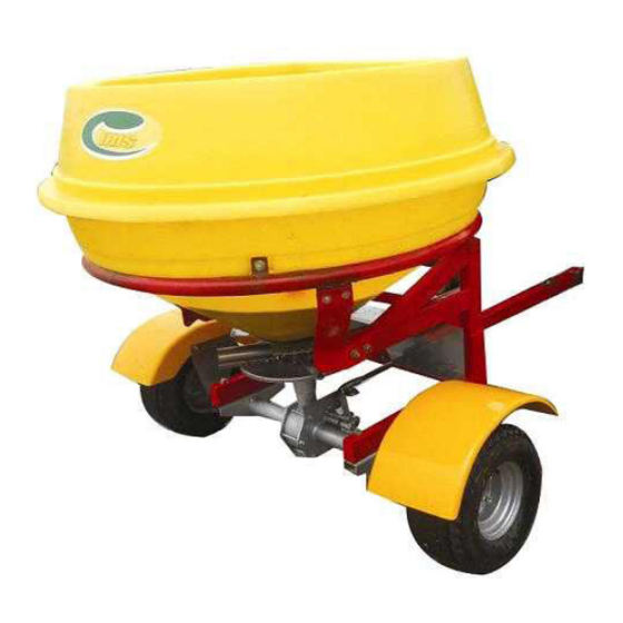
3. Parts Pull-Type Spreader(ITS-400P,700P,900P) ➀ ➁ ④ ➈ ➄ ➅ ➆ ➇ ➉ ➂ ➀ Hopper ➁ Frame ➂ Tires ➃ Tongue ➄ Shutter & Spreading Direction ➅ Vanes ➆ Disc ➇ Gearbox ➈ Prevention Plate ➉ Mud Guard - 2 -... -
Page 5: How To Operate
4. How to Operate 1) Connect the links of spreader to the links of ATV or a small tractor. 2) Check for horizontality after fastened the equipment to ATV or a tractor. 3) If the horizontality is not maintained, use the horizontality-maintaining pole to do so. - Page 6 6) Adjust spread rate by using adjusting lever.(Cable remote control) 7) Spread fertilizer by hauling through ATV or a compact tractor. 9) Three spreading patterns : A simple adjustment of shutter level allows direction of distribution towards the righthand side or towards the lefthand side. - 4 -...
-
Page 7: Important Safety Information
8) You may require an additional adjustment by moving the individual vanes when the condition of fertilizer changes(weight, condition(wet or dry), etc) Moving the vane tips forward(No.1) will carry more material to the lefthand side. Moving the vane tips backward(No.3) will allow more material to be spread to the righthand side Please have a test spreading after each adjustment. -
Page 8: Checkup
6. Checkup 1) Make sure to apply Lubricant where needed and check for loosen nuts and bolts before operating. 2) Check for air pressure on the tires. 3) Before operating, please check for lubrication, and connection of the parts. 4) Test drive the equipment before actual use. 7. - Page 9 8. SPREADING CHART FOR FERTILIZER ITS-400P,700P SPREAD VEHICLE QUANTITY TO BE SPREAD, IN KGS PER HECTARE AT CONTROL LEVER SETTING INDICATED FERTILIZER WIDTH SPEED TYPE (METERS) (km/h) 111.7 444.6 1014.6 1813.7 2561.6 3327.7 4261.3 5379.7 Coarse Grain 12.5 39.2 636.4 898.8 1167.6 1495.2...
- Page 10 ITS-900P SPREAD VEHICLE QUANTITY TO BE SPREAD, IN KGS PER HECTARE AT CONTROL LEVER SETTING INDICATED FERTILIZER WIDTH SPEED TYPE (METERS) (km/h) 120.5 479.7 1094.7 1956.9 2763.8 3590.4 4597.7 5804.4 Coarse Grain 40.7 161.9 369.4 660.3 932.5 1211.4 1551.3 1958.4 Fertilizers 12.0 21.8...
-
Page 11: Parts Sales & Trouble Shooting
9. Parts sales & Trouble shootings Parts sales 1) The parts list provided is in compliance with ITS-400P,700P,900P standards. Refer to this list when order any parts. 2) Follow next steps as below when order parts: ex) We would like to order 1 unit of Vane Model Number Description... - Page 12 11. Assembling instructions for ITS B MODEL 1) GEARBOX AND AXLE 2) FRAME 1) HOPPER BRACE 2) HOPPER RING A) Fix the frame on the proper bracket of gearbox and axle by 4 SCREWS M12x110, 4 LOCK NUTS M12, 8 WASHERS M12 B) Fix the hopper brace on the proper bracket of the frame by 4 SCREWS M12x75, 4 LOCK NUTS M12,...
- Page 13 C) Fix the hopper ring on the proper bracket of the frame and hopper brace by 8 SCREWS M10x40, 8 LOCK NUTS M10, 16 WASHERS M10 - 11 -...
- Page 14 1) DISC&VANE, DISC'S UPPER BUSHING AND SPREADING SHAFT A) Fix the spreading shaft into the disc' upper busing by 1 SUS SCREW M8x45 and 1 SUS FLANGE NUT M8 B) Tighten - 12 -...
- Page 15 C) Fix the disc&vane, disc's upper bushing&spreading shaft on the proper rotary bushing of the gearbox and axle by 6 SUS SCREWS M8x25, 4 SUS LOCK NUTS M8 - 13 -...
- Page 16 1) HOPPER 2) SHUTTER & LOCK SET - 14 -...
- Page 17 A) Place the hopper into the hopper ring by centering B) Fix the hopper brace on the proper bracket of the hopper ring by 4 SUS SCREWS M10x40, 4 SUS LOCK NUTS M10, 8 SUS WASHERS M10 C) Tighten D) Tighten E) Tighten F) Tighten - 15 -...
- Page 18 1) LOWER AGITATOR 2) CLUTCH LEVER SET A) Insert the lower agitator and then fix the lower agitator on the shaft by 8 SUS SCREWS 8x45 and 1 SUS FLANGE NUTS M8 B) Tighten C) Assemble the clutch lever set - 16 -...
- Page 19 E)1 key 8x7x40 G) Fix the clutch lever on the proper bushing of the frame by 1 SCREWS M10x25 and 1 WASHER M10 H) 1 SCREWS M8x15 I) Tighten - 17 -...
- Page 20 J) Assemble the clutch lever set with gearbox clutch M) Assemble the spring - 18 -...
- Page 21 1) LEVER SET AND ADJUSTING BAR SET A) Fix the lever cable on the proper bracket of the frame by 2 SCREWS M6x20 and 2 LOCK NUTS M6 B) Tighten C) Fix the adjusting bar B on the proper bracket of the frame by 1 SCREWS M10x25 and 2 NUTS M10 - 19 -...
- Page 22 D) Tighten E) Fix the lever cable on the proper bushing of the lever cable by 1 SCREWS M8x25 and 1 LOCK NUTS M8 F) Tighten G) Fix the adjusting bar A on the proper hole of the shutter by 1 WASHER M10 and 1 RPIN - 20 -...
- Page 23 H) Fix the adjusting bar A on the proper hole of the adjusting bar B by 1 WASHER M10 and 1 RPIN 1) PREVENTION PLATE A) Fix the prevention plate on the proper bracket of the frame by 2 SUS SCREWS M10x25, 2 SUS SPRING LOCK WASHERS M10, 2 SUS NUTS M10 and 4 SUS WASHERS M10 B) Tighten...
- Page 24 1) DRAWBAR SET A) Fix the drawbar tube on the proper bracket of the frame by 2 SCREWS M12x75, 2 LOCK NUTS M12, 4 WASHERS M12 B) Fix the drawbar brace on the proper bracket of the frame by 2 SCREWS M10x35, 2 LOCK NUTS M10, 4 WASHERS M10 C) Fix the drawbar brace on the proper bracket...
- Page 25 D) Tighten E) Tighten F) Tighten - 23 -...
- Page 26 1) MUD COVER BRACE 2) MUD COVER 3) 18x8.5-8(ITS-400P,700P), 20x10-8(ITS-900) A) Fix the mud cover brace on the proper bracket of the drawbar tube by 1 SCREWS M10x50, 1 SPRING LOCK WASHERS M10, 1 NUTS M10 and 2 WASHERS M10 B) Tighten - 24 -...
- Page 27 C) Fix the tire&wheel on the wheel flange by 8 CAP NUTS M12 D) Tighten E) Fix the mud cover brace on the proper bracket of the axle by 4 SCREWS M10x25, 4 SPRING LOCK WASHERS M10, 4 NUTS M10 and 8 WASHERS M10 F) Tighten - 25 -...
- Page 28 1) EXTENSION HOPPER(KS-700P, KS-900P) A) Place the extension hopper on the hopper B) Fix the extension hopper on the hopper by 8 SCREWS M8x30, 8 SPRING LOCK WASHERS M8, 8 NUTS M8 and 16 WASHERS M8 C) Tighten - 26 -...
-
Page 30: Certificate Of Quality Assurance
CERTIFICATE OF QUALITY ASSURANCE All products manufactured and sold by IRIS SPREADERS, Co. are designed and assembled in accordance with regulations on farm machinery under very strict quality management. If the product is managed and used in accordance with instructions on regular check-ups and maintenance schedule provided in the owner’s operation manual then we assure you that the product always will be at its best condition and outstanding performance, and... - Page 31 ▶ On delivery the customer should check the censure that the machine has not been damaged in transit, and that it complies with that ordered as that it is complete with all the accessories as specified in the purchase contract. If it is found defective, a written complaint should be sent within 8 days of receipt of the same.
- Page 32 3) Any malfunction or defect caused by using unspecified fuel (low quality fuel or contaminated fuel) 4) Any malfunction caused by not complying with instructions prescribed in Owner’s Operation Manual or Warning Signs 5) Any defect caused by unauthorized modification of the product or use of non-genuine parts.
- Page 33 6. In case we upgrade the specifications of certain model, we do not have any responsibility to upgrade the already-sold-equipments. 7. TRANSFER OF WARRANTY Since we honor the remaining warranty time even after the transfer of ownership through sale or donation, it is very important to acquire the Certificate of warranty when transfer of the product takes place.
- Page 34 WARRANTY INFORMATION ○ In order for us to guarantee our highest quality on our products, we offer complimentary inspections designated agencies. malfunction occurs caused by manufacturing defect during warranty period, we will repair or replace the parts at free of charge. ○...
- Page 35 After Service Execution Report DATE PERFORMED TECHNICIAN CONFIRMED...
- Page 37 P.O. BOX 638 WODONGA VIC 3689.
Need help?
Do you have a question about the agromaster ITS-400P and is the answer not in the manual?
Questions and answers