Table of Contents
Advertisement
Quick Links
Advertisement
Table of Contents

Related Manuals for PSI PP 3034


Summary of Contents for PSI PP 3034
- Page 1 User´s Manual PP 3034...
- Page 2 PP 3034 User Manual Acknowledgements PCL is a Trademark of Hewlett Packard Company. A Publication of PSi Laser GmbH Hommeswiese 116 a 57258 Freudenberg/Germany http://www.psi-laser.de Version: 5112 991 21751 October 2021 Great care has been taken to ensure that the information in this handbook is accurate and complete.
-
Page 3: Content Safety Regulations
SAFETY REGULATIONS Safety Regulations for the Laser Printer PP 3034 and Paper Stacker iPS 3034 The laser printer PP 3034 and the intelligent Paper Stacker iPS 3034 fulfil the safety regulations according to IEC 62368-1 for information technology equipments. The mains cable must be connected only to a grounded protected wall-socket. The printer´s mains voltage must agree with the local mains voltage. - Page 4 Electromagnetic Compatibility We certify that the equipment at issue, Type: Printer PP 3034 and the intelligent Paper Stacker iPS 3034 correspond to the laws and regulations ruling electromagnetic compatibility of appliances (2014/30/EU) and, the- refore, fulfil the requirements for conformity marking with the CE-sign.
- Page 5 Also ensure that the cables of the printer do not interfere with the output paper path. The intelligent Paper Stacker iPS 3034 can only be used in conjunction with the printer PP 3034. Caution: Connector not located in limited Power Source! It is only for connecting the Paper Stacker (iPS 3034).
- Page 6 PP 3034 User Manual Notes to Operators and Key Operators 1 The following safety rules should be observed • The unit should be kept free from moisture, dirt, dust and exposure to heat and direct sun- light at all times.
- Page 7 PP 3034 User Manual 1.4 CE Marking (Declaration of Conformity) (For European Users) This product complies with the following EU directives: 2014/35/EU and 2014/30/EU directives. This declaration is valid for the area of the European Union(EU) only. This device must be used with shielded interface cable and shielded network cable.
- Page 8 PP 3034 User Manual 2.4 Laser treatment WARNING The print head unit is NOT A FIELD SERVICE ITEM. Therefore, the print head unit should not be opened under any circumstances. 2.5 Label Indications • For United States CAUTION Use of controls, adjustments or performance of procedures other than those specified in this manual may result in hazardous radiation exposure.
- Page 9 PP 3034 User Manual • For Denmark ADVARSEL Usynlig laserstråling ved åbning, når sikkerhedsafbrydere er ude af funktion. Undgå udsttelse for stråling. Klasse 1 laser produkt der opfylder IEC 60825-1:2014 sikkerheds kravene. • For Finland, Sweden VAROIUS! Laitteen käyttäminen muulla kuin tässä köyttöohjeessa mainitulla tavalla saattaa altistaa käyttäjän turvallisuusluokan 1 ylittävälle näkymättömälle lasersäteilylle.
-
Page 10: Table Of Contents
1.2.6 ALIGN THE PRINTER ON THE IPS ..................22 1.2.7 MOUNT THE PENDULUM ON THE IPS 3034 ..............23 1.2.8 CONNECT THE PRINTER PP 3034 WITH THE IPS 3034 ...........24 1.3 OPERATING THE IPS 3034 .......................24 1.3.1 ADJUSTING THE PAPER EXIT TRAY TO THE USED PAPER LENGTH .......24... - Page 11 2.4.1 PROFIL AUSWAHL ......................40 2.4.2 PAPER MENU ........................41 2.4.3 PCL-MENUE ........................42 2.4.4 HEXDUMP-MENUE ......................42 2.4.5 GENERAL MENU ......................43 2.4.6 CONFIG.-MENU ......................43 2.4.7 CLOCK MENU ........................44 2.4.8 TEST MENU ........................44 2.4.9 INFO MENU ........................45 2.5 EXPLANATION OF INDIVIDUAL MENU ITEMS ...............45 2.6 MENU MODE CHANGE PROFILE .....................47 2.7 GENERAL MENU ........................56 2.8 MENU MODE BASIC SETTINGS ....................57...
-
Page 12: Preface
PREFACE About this Manual This manual covers the printer PP 3034 and the intelligent Paper Stacker iPS 3034. The structure of this manual is such that the operator is led step-by-step through the various procedures. Starting with unpacking and installation of the consumables it moves on to set- ting-up configuration parameters and ends with the mounting of options. - Page 13 Appendix A Programming This appendix describes commands extension of PCL5 and PJL in section 1 and 2. The Bar code programming is described in section 5. These command structures are valid for the PP 3034 Laser Printer with PCL5 Emulation.
-
Page 14: Installing The Printer Pp 3034 And The Intelligent
Installation 1. INSTALLING THE PRINTER PP 3034 AND THE INTELLIGENT PAPER STACKER IPS 3034 1.1 REQUIREMENTS TO THE LOCATION OF THE PRINTER In this chapter the preconditions are described concerning the environment, the physical prere- quisites, and the demand for space which are required for installation of the printer. - Page 15 Installation Note: The printer must never be installed such that its right side (paper exit) points to a window. If the top cover is opened to clear a paper jam or to perform maintenance actions sunbeams would directly fall onto the photoconductor drum and would permanently destroy its surface after an impact period of about 1 minute.
-
Page 16: A First Look At The Devices
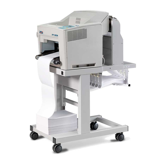
6 Paper exit 7 Pendulum 8 Paper exit tray 9 Castors Note: The intelligent Paper Stacker (2) – also called iPS 3034 - is a special option. Note: Printer drivers for Windows ® are available from the PSi Laser website Page 16... -
Page 17: Unpacking The Intelligent Paper Stacker - Ips 3034
Installation 1.2.1 UNPACKING THE INTELLIGENT PAPER STACKER - IPS 3034 Check delivery for completeness Please check the delivery for damage. If a part is damaged, the supplier must be contacted immediately. Unpacking of iPS 3034 • Remove top cover (1). •... -
Page 18: Unpacking And Installing The Printer
1.2.2 UNPACKING AND INSTALLING THE PRINTER The printer PP 3034 is delivered in a package with the following label. Note: Before unpacking the PP 3034 should be checked whether the specified mains voltage corresponds to the local power supply. Otherwise, contact the supplier. - Page 19 Installation Unpacking the printer • Remove Styrofoam buffer (1) - see previous page. • Remove positions (3), (4) und (5) - see previous page. • Remove IC-Cartridge (6) • Lift printer (7) with 2 persons out of the box After removing the plastic foil lift the printer (2) with two persons using the transport grips (see following pictures) on the left and right side of the printer (2) and put it onto a table or onto the iPS 3034.
-
Page 20: Removing The Transport Locks Of The Printer
Installation 1.2.3 REMOVING THE TRANSPORT LOCKS OF THE PRINTER • Remove the security strips (1). • Push the latch (2) in direction of arrow and open the top cover (3). • At left bottom side of the printer is an additional protective strip (4). Remove the strip carefully. -
Page 21: Installing The Image Cartridge
Installation 1.2.4 INSTALLING THE IMAGE CARTRIDGE • Open the top cover of the printer. • Unpack the Image Cartridge (1) and shake it like shown on the pictograms on top of the unit. • Remove both lock strips (2) of the Image Cartridge. •... -
Page 22: Mounting The Tear Off Bar
• Position the tear off bar (1) and fix it with the included longer screws. 1.2.6 ALIGN THE PRINTER ON THE IPS Move the Printer PP 3034 (1) to the edge (3) of the table from the iPS 3034 (2). The right and left side of the printer must be flush with the iPS. -
Page 23: Mount The Pendulum On The Ips 3034
Installation 1.2.7 MOUNT THE PENDULUM ON THE IPS 3034 • Remove the 5 screws (3) each at both side co- vers (2) of the pendulum mount (1) • Remove the screws (6) from the frame (5) • Place pendelum mount (9) on the frame (5) and fix it with the screws (6) at right and left side. -
Page 24: Connect The Printer Pp 3034 With The Ips 3034
Installation 1.2.8 CONNECT THE PRINTER PP 3034 WITH THE IPS 3034 • Power off the printer • Plug the interface cable (2) from the IPS into the socket of the control unit and tighten the screws. • The ground cable (1) from the iPS 3034 must be fixed with the cablelug of the printer 1.3 OPERATING THE IPS 3034... -
Page 25: Tray Extension
Installation The length of the pendulum (6) must so be adapted to the paper length. • Loose the thumbscrews (1) at front and rear side of the pendulum • Move the pendulum length (6), de- pending on the paper length up or down (the perforation of the conti- nuous paper must be visible below the pendulum). -
Page 26: Remove Paper From The Ips
Installation 1.3.3 REMOVE PAPER FROM THE IPS There is a switch (1) at the front of the table (below the operator panel) which cause the paper exit tray (2) to move up or down. Move the paper exit tray (2) down and remove the paper. -
Page 27: Power On/Off Switch
Installation 1.5 POWER ON/OFF SWITCH • Make sure that the power switch of the printer is placed in the Ο (OFF) (2) position. • Connect the printer to the mains using the power cord (1). Note: Printer and iPS will be switched ON or OFF with the power switch (2). When switched ON the printer performs an internal self test which checks the electronics, fans, and the motors for the paper transport mechanism. -
Page 28: Inserting Fanfold Paper
Installation 1.6 INSERTING FANFOLD PAPER Note: When using the printer in combination with the stacker iPS 3034 the default setting for the FOLD = POSITIVE, check whether the folding points outwards behind the first page (the fold points the operator). If the folding is negative (pointing to the printer), then the first page has to be separated or the para- meter FOLD = NEGATIVE must be selected (see Explanation of the Individual Menu Items). - Page 29 Installation • Pull and turn the knob to the right side (small paper) or to the left side (wide paper) so that the tractors are adjusted to the width of paper. • Open the first tractor covers (2), insert the Paper up to the second tractor and close one of the first tractor covers.
-
Page 30: Printer Operation
Using the Printer 2. PRINTER OPERATION 2.1 CONTROL PANEL • gives information about the printer status • controls various parameter settings • allows manual control of the paper hand- ling 2.1.1 DESCRIPTION OF THE DISPLAY ELEMENTS • The two-line 16-digit liquid crystal display (LCD) (1) usually shows the current status of the printer. -
Page 31: Function- And Navigation Keys
Using the Printer If the printer is in the OFFLINE mode status information, error messages, or menu messages are displayed. The structure of the display of status and error messages is: S T O P ( 1 ) M E S S A G E Example: Printer is warming up: S T O P ( 1 ) - Page 32 Using the Printer Key FORM FEED in operation mode OFFLINE BUTTON DISPLAY/FUNCTION FORM FEED • Activates a form feed Key MENU in operation mode OFFLINE DISPLAY/FUNCTION OFFLINE (1) PROFILE SELECTION • Aktivates the menu mode Key CANCEL in operation mode OFFLINE DISPLAY/FUNCTION OFFLINE (1) •...
-
Page 33: Menu Mode
Using the Printer 2.1.4 MENU MODE All operator selected features are accessible via the control panel and combined in the printer MENU. This feature provides: • Easy handling of configuration (language, etc.) • Quick parameter changes • Activation of test functions There are four entry points: •... - Page 34 Using the Printer Selection of functions and parameters at a certain menu level: • By pressing the key the next or previous menu item will be reached. The menu has a loop function, means after the last item in a structure is reached, the first item will be displayed again.
- Page 35 Using the Printer Confirm a new Selection Press confirmed value is displayed with an asterisk (*) in the last position as shown in the picture before. Note: All new values have to be saved by activating to be saved. The menu mode can be left with pressing key Note: A satatus page with all actual parameters can be printed with the function SELFTEST.
-
Page 36: Configuring The Printer
Configuration of the Printer 2.2 CONFIGURING THE PRINTER Was versteht man unter „Konfigurieren“? This chapter describes how to use the control panel and menu to set up or configure your printer so that the printer and your computer system can communicate correctly with each other. The most important menus are: •... -
Page 37: Profiler 3034
The Profiler is software for editing printer profiles of PP 3034. The contents of the 50 printer profiles (macros) are read from PP 3034 and stored on the PC / notebook. There they can be changed and updated when needed in the printer. The program requires no installation and has a small memory footprint, so for example it can be started directly from a USB disk. - Page 38 Configuration of the Printer Printing all profiles In order to print the content of all profiles the function CONFIG. PRINT has to be activated. Steps Example to Start a Self Test must be processed and the menu item CONFIG. 1 to 6 from chapter PRINT can be selected.
-
Page 39: Menu-Structure
Configuration of the Printer 2.3 MENU-STRUCTURE PUSH PAPER TO TEAR PAPER MENU OFF BAR FORMAT PAPER LENGTH PAPER RETRACT TO LENGTH FACTOR OFFLINE (n) STARTING POSITION IMAGE WIDTH TEAR OFF FORM STACKER LENGTH SELECT PROFILE NEG. FORM EJECT ORIENTATION SELECT PROFILE LANDSCAPE MODE FEED N PAGES ORIENT. -
Page 40: Menu Item Description
Configuration of the Printer 2.4 MENU ITEM DESCRIPTION PARAMETER VALUE TEAR OFF FORM SELECT PROFILE • see below NEG. FORM EJECT FEED N PAGES • 1..16 • POSITIVE |< * SELECT FOLD • NEGATIVE |> CHANGE PROFILE • see below BASIC SETTINGS •... -
Page 41: Paper Menu
Configuration of the Printer 2.4.2 PAPER MENU Entry Point = CHANGE PROFILE ---> PAPER MENU PARAMETER VALUE • A4 PAPER • LETTER • CUSTOM PAPER LENGTH • 12 Inch (only for CUSTOM) (Range: 3 up to 20 inch; in Steps of ¼ oder 1/6 inch) LENGTH FACTOR •... -
Page 42: Pcl-Menue
Configuration of the Printer 2.4.3 PCL-MENUE Hinweis: Das PCL MENUE wird nur angezeigt, wenn im HAUPTMENUE die EMULATION = PCL ist. Entry Point= CHG PROFILE ---> PCL-MENU PARAMETER VALUE FONT NUMBER ( Range: Font No. 0 up to 54) • 10.00 PITCH (for Font No. -
Page 43: General Menu
Configuration of the Printer 2.4.5 GENERAL MENU ENTRY POINT = CHANGE PROFILE ---> GENERAL MENU PARAMETER VALUE • PCL EMULATION • HEXDUMP • IGP • OFF AUTO FORM FEED (Range: OFF or 1 up to 120 sec.) Only available with DATA in buffer •... -
Page 44: Clock Menu
Configuration of the Printer PARAMETER VALUE • NO FABRIKWERTE • YES • NO RESET TRU • YES 2.4.7 CLOCK MENU Entry Point = BASIC SETTINGS ---> CLOCK MENU PARAMETER VALUE WEEKDAY • MONDAY...SUNDAY • 1..31 MONTH • JANUARY ...DECEMBER YEAR •... -
Page 45: Info Menu
PP 3034 User Manual 2.4.9 INFO MENU Entry Point = TEST MODE ---> INFO MENU AUSWAHL WERT / PARAMETER PRINTER TYPE • Displays the printer model (here 3034) • Displays the firmware version of the hardware ENGINE ID controller FIRMWARE VERS. - Page 46 Configuration of the Printer FEED N PAGES Pressing causes a feed by N pages, depending on the form length. The value is between 1 - 16 pages and can be changed via the menu. Pressing the button feeds one page forward. As the [ONLINE] button is pressed, the selected number of blank pages will be fed before the print job is printed.
-
Page 47: Menu Mode Change Profile
Configuration of the Printer 2.6 MENU MODE CHANGE PROFILE Configuration of a specific Profile. PAPER MENU PAPER A choice out of three different paper sizes can be made: LETTER CUSTOM When selecting A4 or LETTER, the printer automatically sets all parameters that determine the arrange- ment of the print image on the sheet. - Page 48 Configuration of the Printer IMAGEWIDTH The print image is always centered on one side - not aligned with the left or right margin. The width of the printed image can vary from min. 0.5 inches (12.7 mm) to max. 11.00 inches (279.4 mm) can be set with a step size of 0.05 inches (1.27 mm).
- Page 49 Configuration of the Printer LANDSCAPE MODE The orientation of the print image is influenced by this parameter. Setting Landscape Mode to REVERSE (default) rotates the image of LANDSCAPE to REVERSE LANDSCAPE and REVERSE LANDSCAPE to LAND- SCAPE. This makes continuous pages with landscape orientation readable like a book. Selection of PCL COMPATIBLE is according to the landscape definition of PCL i.e.
- Page 50 Configuration of the Printer ORIENT.MODE (ORIENTATION MODE) The ORIENTATION MODE defines the print image rotation for CUSTOM paper format. Setting the ORIEN- TATION MODE to FIXED (default) ensures that the print orientation of a form with paper length shorter than the image width is not rotated. Setting the ORIENTATION MODE to AUTOMATIC rotates the print image if the form length is shorter than the image width.
- Page 51 • IGNORE: Any command to change the paper format will be ignored; the paper format can only be modified via the operator panel. Note: A PAPER SELECTION by the printer driver requires the RECOGNIZE or PJL ONLY setting. The PSi prin- ter drivers for Windows use PCL and PJL sequences.
- Page 52 Configuration of the Printer TONER DENSITY This parameter allows adjusting the toner density. Possible values are: • XLOW • LOW • MIDDLE (default value) • HIGH • XHIGH VER SHIFT (Vertical Shift) HOR SHIFT. (Horizontal Shiftl) The parameters VER SHIFT and HOR SHIFT allow to precisely position the print image vertically (-20...+50/100) and horizontally (!50...+50/100).
- Page 53 Configuration of the Printer PITCH The character density is defined as FONT NUMBER (Font) 0 and 39 to 44 as character spacing. The cha- racter spacing can be 0.44 to 99.99 characters per inch, the default value is 10.00 characters per inch. Depending on whether the characters have a fixed spacing or whether the font is proportional, in the case of fonts with a fixed spacing, each character is of the same width.
- Page 54 Configuration of the Printer DISPLAY SYMBOL SET ID NUMBER PS TEXT PS text VN INTL Ventura International VN US Ventura US MS PUBL Microsoft Publishing MATH-8 Math-8 PS MATH PS Math VN MATH Ventura Math PI FONT Pi Font LEGAL Legal ISO-4 ISO United Kingdom...
- Page 55 Configuration of the Printer LEFT MARGIN This parameter defines the displacement of the first print position of a print line from the left border of the printable area. Any value from 0 up to 999 positions can be selected; factory default value is 0. RIGHT MARGIN The parameter value defines the distance of the last print position within a line from the left border of the logical page.
-
Page 56: General Menu
Configuration of the Printer 2.7 GENERAL MENU The operating parameters for the respective print job are defined in the GENERAL MENU. EMULATION The Emulation determines the printer‘s set of command codes. Default emulation is PCL (PCL5E). The function HEXDUMP is useful to analyze the data received by the printer. Control codes are not executed, instead all data including command codes are printed out in hexadecimal format and as ASCII characters. -
Page 57: Menu Mode Basic Settings
Configuration of the Printer FUSER MODE The FUSER MODE indicates how to handle the paper movement and fuser control after a tear off. Selectable values are: • ENHANCED (default) • STANDARD If the STANDARD value is selected for FUSER MODE the following procedure is carried out after tearing off paper or newly inserted paper: •... -
Page 58: Clock Menu
Configuration of the Printer LANGUAGE Selects the language for the messages that appears on the display of the printer control panel. Default is ENGLISH; available are: ENGLISH, FRANCAIS, and DEUTSCH (German) MENU ACCESS The menu CONFIG MENU has been extended by the new function MENU ACCESS, defining the access rights to various submenus. - Page 59 PP 3034 User Manual PANEL TEST Use this point to check all Operator Panel display functions. SELF TEST This selection starts the printout of the test page with the actual configuration settings of the actual Pro- file and diagonal character test CONT.
- Page 60 Configuration of the Printer TYPEFACE PITCH / POINT FONT # OrigGaramond SWC Bold scalable I 23 OrigGaramond SWC Italic scalable I 24 OrigGaramond SWC Bold Italic scalable I 25 Audrey Two SWC scalable I 26 Flareserif82 1 SWC scalable I 27 Flareserif82 1 SWC Bold scalable I 28...
- Page 61 Displays the actual Engine Firmware version. FIRMWARE VERSION Displays the current version of the operating system of the printer (PPOS, PSi Printer Operating System). CPC-FPGA VERSION The current version number of the firmware of the printer controller is displayed here.
-
Page 62: Maintenance
Maintenance and Care 3. MAINTENANCE Recommended material We recommend the following materials and cleaning agents for maintenance: • Lint-free cloth • Special toner vacuum cleaner • tweezers 3.1 Preventive maintenance and cleaning Periodic cleaning can be carried out by the user at intervals of 6 months. If there are problems with the paper transport, the maintenance intervals should be reduced. -
Page 63: Clearing Paper Jams
Maintenance and Care 3.2 CLEARING PAPER JAMS Division of the chapter First the category of the error message will be identified. The categories are: • Traffic jam in the tractor • Jam in the area of the print cartridge (Image Cartridge) •... -
Page 64: Paper Jam At Image Cartridge
Maintenance and Care 3.2.3 PAPER JAM AT IMAGE CARTRIDGE • Turn off the printer. • Open the top cover. • Remove the image cartridge. • Turn the black paper guide (1) upwards by 90 ° and remove it. • Separate the jammed paper at the perforation. •... -
Page 65: Papier Jam In Ips 3034 (Stacker)
Maintenance and Care 3.2.4 PAPIER JAM IN IPS 3034 (STACKER) A paper jam in the storage system is monitored by an optomechanical sensor in the paper guide. If the sensor is triggered, the printer stops. You first clear the jam by removing the paper web in the area of the tractor, IC cartridge and fusing unit as described in the previous articles. -
Page 66: Replacement Of Tru (Transfer Roller Unit)
Maintenance and Care 3.2.5 REPLACEMENT OF TRU (TRANSFER ROLLER UNIT) After a lifespan of approx. 150,000 printed pages, the transfer roller unit (1) (TRU) must be replaced by the user. This is indicated by the message EXCHANGE TRU on the display of the control panel. Note: Do not press the black foam roller (2) on the TRU (1). -
Page 67: Inserting The Tru (Transfer Roller Unit)
Maintenance and Care 3.2.4.1 INSERTING THE TRU (TRANSFER ROLLER UNIT) Note: Be careful not to push the TRU‘s black foam roller. This can lead to impairment of the printed image. • Push the blue hook claw (3) up again and insert the new TRU on one side. •... -
Page 68: Troubleshooting And Diagnosis
Troubleshooting and Diagnostics 4. TROUBLESHOOTING AND DIAGNOSIS Division of this chapter 1. First find the category into which the problem with your printer can be classified. The categories are: • Power supply problems • error messages 2. Find the symptom description that best matches the printer malfunction. 3. - Page 69 Insert new IC-Cartridge IC-EINHEIT FEHLT IC-EINHEIT FEHLT Keine Druck-Kartusche installiert Druckkartusche einsetzen INVALID IC INVALID IC Wrong Image Cartridge Install an IC from PSi EXCHANGE IC EXCHANGE IC IC-Cartridge used Install new IC-Cartridge EXCHANGE TRU EXCHANGE TRU Transfer-Roller-Unit used Install new Transfer-Roller-Unit...
- Page 70 Troubleshooting and Diagnostics DISPLAY MEANS... MEASURE The iPS is in the phase of the initializati- on. The Paper Exit Tray is moving up and STACKER BUSY STACKER BUSY down and stops at working position. The Please wait printer does not start in this time any print job.
- Page 71 Troubleshooting and Diagnostics DISPLAY MEANS... MEASURE Fan trouble n = 1. Cooling fan of the high voltage Power Printer OFF and On board stopped. again. SERVICE FAN n SERVICE FAN n 2. Sucking fan of the high voltage board stopped. If error still there call Service 3.
-
Page 72: Technical Data
Technische Daten 5. TECHNICAL DATA The technical data specified in this chapter are applicable to the printer PP 3034. Printer Specification • Up to 44 pages per minute (Letter Landscape) • Up to 34 pages per minute (11 inch page length) Print Speed: •... - Page 73 • Drucker mit iPS: 540 x 1.208 x 1.118 mm (W x H x D) Note: Printer drivers are available for MS-Windows(tm) operating systems from Windows XP onwards. Ad- ditionally, printer configuration software Profiler and device types for SAP R/3 and Linux are available from the PSi website ( www.psi-laser.de Seite 73...
-
Page 74: Paper Specification
Paper Specification 6. PAPER SPECIFICATION 6.1 BASIC THEORY OF OPERATION Laser printers use the electrophotograhic technology. The laser beam writes an electrostatic image onto a rotating photosensitive drum (Photoconductor). As this image passes the developer station, a dry, powde- ry toner is attracted to the image areas. The developed image then advances to the transfer station where the drum contacts the fanfold paper and the toner image is electrostatically transferred onto the paper. -
Page 75: Guidelines And Specifications For Selected Fanfold Paper
Paper Specification 6.4 GUIDELINES AND SPECIFICATIONS FOR SELECTED FANFOLD PAPER The nature of continuous paper varies depending on the manufacturer. As a manufacturer of laser prin- ters have no influence on this fact, it is to pay attention to the quality of the continuous paper in Range responsibility of the user. - Page 76 Paper Specification Pic. 004 4 mm ± 0.1 mm 0.16 inch ± 0.004 inch 6 mm ± 0.7 mm 0.24 inch ± 0.028 inch 6 mm ± 0.7 mm 0.24 inch ± 0.028 inch Page 76...
- Page 77 Paper Specification Perforation Note: All measurements conditioned at 23 C (68° F) and 50% RH the center of horizontal and vertical perfora- tion must not be cut! Cutted area 0.12 to 0.16 inch (3 to 4 mm) uncutted area 0.04 inch (1 mm) Note: The perforation should not be cut to the paper edges(1)! Page 77...
-
Page 78: Typical Paper Properties For Laser Printers
Paper Specification 6.4.2 TYPICAL PAPER PROPERTIES FOR LASER PRINTERS Description Specifications Applicable Method 5mm (0.2 inch);no diagonal curl Flatness deviation (Rolls and warping) conditioned (23 ± 2) C and (15 ± 5) % RH Max. 0,8% Stability of dimension cross Test Condition in heat chamber to paper path... - Page 79 Paper Specification Description Specifications Applicable Method for every 10% difference of humidity between 40 and 60% Humidity stretching DIN 53 130 • length maximum 0.04% • cross maximum 0.2% Tearing length • Minimum 5000 m DIN EN ISO 1924-2 Smoothness by Bekk •...
-
Page 80: Label Carrier Properties
Paper Specification 6.4.4 LABEL CARRIER PROPERTIES Description Specifications Applicable Method Specific volume • (1,3 ± 0,2) cm DIN EN ISO 438 Arch • Maximum: 5 mm DIN 6724 • vertical minimum 85 N Break stability DIN 53 112 • horizontal minimum 40 N Crack stability •... - Page 81 Paper Specification Description Specifications Applicable Method Difference etween humidity • maximum 10% RH of paper and ambiance Difference between paper • Maximum ± 2° C and room temperature • 5mm (0.2 inch); no diagonal Flatness deviation curl at DIN 6724 (Roles and warping) •...
-
Page 82: Appendix C Miscellaneous
Appendix C APPENDIX C MISCELLANEOUS C-1 ORDER NUMBERS Image Cartridge: 8709 003 34001 Transfer Roller Unit (TRU) 8709 003 34002 C-2 PRINTER DRIVERS The printer drivers for Windows ® are available on our homepage: https://www.psi-laser.de C-82...
Need help?
Do you have a question about the PP 3034 and is the answer not in the manual?
Questions and answers
To change the 2-ups printing setting in Printers & Scanners for your PSi PP 3034 printer,