
Related Manuals for Vingtor ETB-5

Summary of Contents for Vingtor ETB-5
- Page 1 Command Talk-Back & Public Address System ETB-5 / ETB-10 / ETB-10A / ETB-100 / ETB-100A TECHNICAL MANUAL A100K11162 v1...
- Page 2 ETB central unit. The following central units (panel version 8.0) are available for the ETB system: Product Item Number ETB-5 Central Unit, Panel Mounted, 5 Lines 3005020022 ETB-10 Central Unit, Panel Mounted, 10 Lines 3005020018...
-
Page 3: Table Of Contents
2.3 Placement of Substations and Loudspeakers ............13 2.4 Terminal Configurations ..................14 2.4.1 ETB-100 Terminal Configurations on PCB .............14 2.4.2 ETB-5/ETB-10 Terminal Configurations on PCB ...........15 2.5 Cable Requirements ....................16 2.6 Power Supply Requirements ..................17 2.7 Volume Adjustment for Substation Lines ..............17 2.8 Extra Signal Device ....................17... - Page 4 6.2 ETB-10/ETB-10A ....................49 6.3 ETB-100/ETB-100A ....................50 7 Connection/Block/Single Line Diagrams ..............51 7.1 ETB-100 Single Line Diagram ................51 7.2 ETB-5/ETB-10 Single Line Diagram ...............52 7.3 ETB-100 PCB Layout ....................53 7.4 ETB-5/ETB-10 PCB Layout ..................55 7.5 ETB-100 Block Diagram ..................57 7.6 ETB-5/ETB-10 Block Diagram ................58 7.7 ETB-100 Cable Connection Diagrams ..............59...
-
Page 5: System Overview
System Overview The ETB-5 & ETB-10/ETB-10A is a Command Talk-Back system with 5 or 10 lines while the ETB-100/ETB-100A is a Command Talk-Back & Public Address system with 10 lines. The ETB-100A can also be used as an emergency Public Address system. The system comprises a central unit and a comprehensive range of substations and other field equipment for use indoors, outdoors, and in noisy areas on marine vessels. -
Page 6: Etb-100 System Configuration
STB-6 ETC-1-TB Signal Unit Central Unit ETB-100 Parallel Station Parallel Station SB-4 SB-4 P-66 P-66 VML-1520 VML-1520 VINGTOR Power Amplifier Substation STB-1 Substation STB-1 Line 1 Line 2 VPA-120 POWER AMPLIFIER Substation HE-112MT Substation STB-2 Line 4 Line 3 VML-15T... -
Page 7: Features
● Public Address operation (ETB-100A) ● 100V line power amplifier (ETB-100/ETB-100A) System Components Central Units, Microphones & Amplifiers Name Description Item No. ETB-5 Central Unit, panel mounted, IP44 - 5 lines 3005020022 ETB-10 Central Unit, panel mounted, IP44 - 10 lines 3005020018 ETB-10A Central Unit with external PA, panel mounted, IP44 - 10 lines... -
Page 8: Functions
ETB-10A, ETB-100, or ETB-100A only (this will be indicated in the section heading). 1.5.2 Line Selection / Single Call Up to 5 substations for ETB-5 and 10 substations for ETB-10/ETB-10A/ ETB-100/ETB-100A can be selected by pressing the respective line button on the central unit. -
Page 9: Group Call
A group of substations can be selected by pressing the respective line buttons. Activation is indicated by a steady green LED. VINGTOR 1.5.4 All Call All call message can be distributed by pressing the ALL button. Activation is indicated by a steady green LED in the ALL button. -
Page 10: Extra Signal In The Etb Central Unit
1.5.8 Extra Signal in the ETB Central Unit An extra signal device can be activated when receiving calls from a substation through a potential-free contact in the central unit. VINGTOR 1.5.9 Handsfree Operation Handsfree operation of central unit or parallel station. Option 1 Central unit with gooseneck microphone MB-30G and foot switch U2410. -
Page 11: External Loudspeaker (Option)
The TALK button on ETB-10A or the PTT switch on the handheld microphone will override the external audio. Normal talk-back functions can not be used in this mode. The external system may be: VINGTOR - VHF radio - Entertainment system - Alarm system... -
Page 12: Simple Public Address (Etb-100A Only)
A single line or group of loudspeaker lines can be set to Simple PA mode. Fixed settings for selected lines are made through DIP switches. All lines can be set to this mode. VINGTOR The remaining lines provide normal Talk-Back function. Line 5... -
Page 13: Installation & Configuration Procedures
Installation & Configuration Procedures General For proper installation and operation of the ETB system, we recommend reading this section thoroughly together with technical and connection drawings in the section 7. All configuration settings such as volume, foot switch, microphone, etc. are located on the ETB main board ETB510. Refer to technical drawings in section 7 Connection/Block/Single Line Diagrams for more detailed information. -
Page 14: Terminal Configurations
Terminal Configurations Pluggable screw terminals for cables of max. 2.5 mm are utilized. Refer to technical drawings in section 7 Connection/Block/Single Line Diagrams for more detailed information. 2.4.1 ETB-100 Terminal Configurations on PCB A100K11162 v1 ETB Command Talk-Back & Public Address System Installation & Operation Manual... -
Page 15: Etb-5/Etb-10 Terminal Configurations On Pcb
2.4.2 ETB-5/ETB-10 Terminal Configurations on PCB Terminal block C1 - C10 (ETB-100/ETB-100A only) ● No. 1-2 for substation line, low impedance ● No. 3-4 for substation line, 100V to extra signal device A100K11162 v1 ETB Command Talk-Back & Public Address System Installation & Operation Manual... -
Page 16: Cable Requirements
Terminal block K1 - K5 (for ETB-5) Terminal block K1 - K10 (for ETB-10/ETB-100) ● No. 1-2: substation line for ETB-10 (not in use for ETB-100) ● No. 3-4: 24V DC to extra signal device ● No. 5: common ground point for each substation screen Terminal block K11 ●... -
Page 17: Power Supply Requirements
Power Supply Requirements ● 24 VDC -10% + 33% (21.6 – 32 VDC) ● Current consumption max. 2A System power supply should be wired and fused independently from other systems: ● 24V DC from ship’s 24V DC system. ● 24V DC from power supply SPS-4 230V AC / 24V DC with automatic switch to 24V DC emergency power supply. -
Page 18: Set Up Single/Group Pa (Etb-100/Etb-100A Only)
Located on keyboard ETB510 See dwg. no. ETB-100_lo| for location. Each line can be set to single or group of PA without talk back. See dwg. no. ETB-100_lo| for location. Jumper marked J12 to J21 for each line (on ETB-100 board) have to be set in 2.12 Set Up Single/Group PA (ETB-100/ETB-100A Each line can be set to single or group of PA without talk back. -
Page 19: Operating Instructions
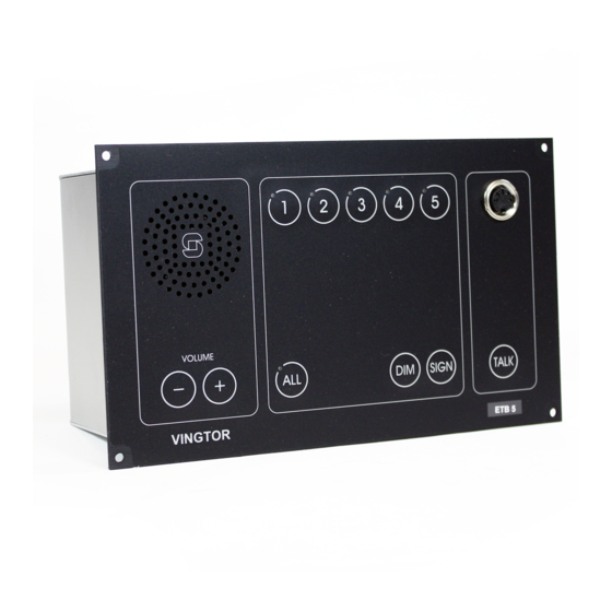
Ingress Protection Rating = IP44 VINGTOR 1. Loudspeaker: For communication and alarm signals 2. Line Buttons: Lines 1-5 for ETB-5, Lines 1-10 for ETB-10/ETB-10A and ETB-100/ETB-100A 3. Green LED: Indication light for each line button 4. Microphone Connector: For gooseneck or handheld microphone 5. -
Page 20: Making A Call To A Substation
Gooseneck Microphone MB-30G Handheld Microphone ETC-1-TB with PTT Foot Switch U2410 for handsfree operation switch of microphone MB-30G 3.1.1 Making a Call to a Substation You can select the substation by pressing the desired line push button. A steady green LED will indicate the activated line. If desired, the signal button SIGN may be pressed to send a tone signal to the selected station. -
Page 21: Making A Call To A Group Of Substations
ETC-1-TB ETB central unit with handheld microphone ETC-1-TB ● Press the PTT switch on the microphone PTT Switch ● Speak clearly into the microphone When the PTT switch is released, the ETB will be in listening mode and you will hear the communication from the selected station in the panel loudspeaker. -
Page 22: Making An All Call
● Press the active line buttons once more to terminate the calls. When the calls terminate, the LEDs will stop lighting. 3.1.3 Making an All Call The message and signal from ETB will be given to all substations, as a one-way message. -
Page 23: Making A Handsfree Call Using Foot Switch
● Speak clearly into the microphone When the foot switch is released, the ETB will be in listening mode, and you will hear the communication from VINGTOR the selected station. L Jumper labeled Jumper for foot switch must be removed for this function. -
Page 24: Receiving A Call From A Substation
3.1.6 Receiving a Call from a Substation An incoming call is indicated by a flashing green LED in the respective line button and a beeping tone in the panel loudspeaker. It will also activate an extra signal unit if installed. Only the ETB central unit can terminate the call. -
Page 25: Receiving Calls From Two Or More Substations
3.1.7 Receiving Calls from Two or More Substations Calls can be received from two or more substations at the same time. The ETB central unit has the 1 priority and can select between calls from the substations. Only the ETB central unit can terminate the calls. Incoming calls are indicated by flashing green LEDs in the respective line buttons and a beeping tone in the panel loudspeaker. -
Page 26: Parallel Communication
Parallel Communication Parallel communication functions with the operation of the ETB central unit from parallel microphones/loudspeakers located on bridge wings or other locations near the central unit where parallel microphones/ loudspeakers are needed. Two parallel stations can be connected. Communication is set up by the ETB central unit. -
Page 27: Operation Of Parallel Communication
3.2.1 Operation of Parallel Communication L Note that line selection and signal have to be set up from the ETB central unit. ETB Central Unit ● Press the line button on the ETB central unit - the call is set up, indicated by a steady green LED ●... - Page 28 Handsfree Operation Parallel Station STB-6GN Handsfree Operation Using Foot Switch ● Press the foot switch ● Speak clearly into the microphone When the foot switch is released, the parallel station will be in listening mode, and you will hear the communication from the selected station in the panel loudspeaker.
-
Page 29: Audio From External Systems (Etb-10A Only)
Audio from External Systems (ETB-10A only) Entertainment, message or alarm messages can be distributed by using the ETB-10A central unit and all substations. An potential-free contact and 0 dB signal from the external system activate the ETB-10A to send the message to all substations. The TALK button on ETB-10A or the PTT switch on the handheld microphone will override the external audio. -
Page 30: Simple Public Address (Etb-100A Only)
Simple Public Address (ETB-100A only) A single line or group of loudspeaker lines must be set to Public Address as a fixed configuration. The Public Address function is set by DIP switches (see section 3.11). L The Talk-Back function can not be used for the lines that are configured for Public Address. -
Page 31: Emergency Public Address (Etb-100A Only)
PA call stations 2 and 3. PA Call Stations Configuration with Gooseneck Microphone PA Call Station 2 PA Call Station 3 VMT-603 VMP-603 PA Call Station 1 ETB-100A VINGTOR Mute A100K11162 v1 ETB Command Talk-Back & Public Address System Installation & Operation Manual... - Page 32 PA Call Stations Configuration with Handheld Microphone PA Call Station 2 PA Call Station 3 VMT-603 VMP-603 PA Call Station 1 ETB-100A VINGTOR Mute A100K11162 v1 ETB Command Talk-Back & Public Address System Installation & Operation Manual...
-
Page 33: Operation From Pa Call Station 1 - Etb-100A
3.5.1 Operation from PA Call Station 1 - ETB-100A ● Press the ALL button - the call is set up indicated by a steady green LED in the ALL button ETB central unit with gooseneck microphone MB-30G ● Press the TALK button for Emergency PA - The operation will mute the General Alarm system and override Talk-Back and single PA calls. -
Page 34: Operation From Substations
Operation from Substations Calls can be made from substations to the ETB central unit by pressing the CALL button. A call is indicated by a flashing green LED and a signal in the ETB central unit. The call is confirmed when the respective line button is pressed. -
Page 35: Operation From Substation Stb-2
3.6.2 Operation from Substation STB-2 Ingress Protection Rating = IP66 Substation STB-2 CALL - Push button for calling central unit. Re-entrant Loudspeaker - Speaker receiving communication from central unit. - Microphone for communication to central unit. Substation Operation ETB Central Unit •... -
Page 36: Operation From Substation Stb-3
3.6.3 Operation from Substation STB-3 Ingress Protection Rating = IP66 Substation STB-3 PTT Switch 10m cable Connector For headset or microphone CALL Push button for calling central unit Loudspeaker For receiving communication from central unit Signal device : Activated from central unit Headset P-MT7 with boom microphone Microphone... -
Page 37: Operation From Substation Stb-5
3.6.4 Operation from Substation STB-5 Ingress Protection Rating = IP44 Substation STB-5 PTT Switch Loudspeaker : For communication from central unit CALL : Push button for calling central unit Connector : For handset HAS-1 or microphone ETC-STB5 Handset : HAS-1 with switch Microphone : ETC-STB5 with... -
Page 38: Operation From Substation Stb-5Gn
3.6.5 Operation from Substation STB-5GN Ingress Protection Rating = IP44 Substation STB-5GN Loudspeaker : For communication from central unit CALL : Push button for calling central unit TALK : PTT switch for talking to central unit Signal device : Activated from central unit Substation Operation ETB Central Unit... -
Page 39: Operation From Substation He-112M / He-112M-T
3.6.6 Operation from Substation HE-112M / HE-112M-T Ingress Protection Rating = IP66 Substation HE-112M Re-entrant Loudspeaker - Speaker for communication from central unit - Microphone for communication to central unit CALL - Push button for calling central unit Substation Operation ETB Central Unit •... -
Page 40: Operation From Substation Vh-10M / Vh-10M-T
3.6.7 Operation from Substation VH-10M / VH-10M-T Ingress Protection Rating = IP65 Substation VH-10M 10m cable Plugbox - CD-2 for VH-10M CALL - Push button for calling central unit Re-entrant Loudspeaker - Speaker for communication from central unit - Microphone for communication to central unit Substation Operation ETB Central Unit... -
Page 41: Operation From Substation Vhm-10 / Vhm-10-T
3.6.8 Operation from Substation VHM-10 / VHM-10-T Ingress Protection Rating = IP66 Substation VHM-10 Cabinet PTT Switch Loudspeaker : For communication from central unit CALL : Push button for calling central unit Microphone : P-66 fixed connected with PTT switch Substation Operation ETB Central Unit... -
Page 42: Operation From Substation Nebb-42Ex
3.6.9 Operation from Substation NEBB-42EX Ingress Protection Rating = IP67 Substation NEBB-42EX with EX Loudspeaker CEAG GHG 411 Ui 690V EEx de IIC T6 PTB Nr.Ex-87.B.1009 1. Call button 2. Re-entrant Loudspeaker Substation Operation ETB Central Unit • Press the call button - Indicated by flashing green LED for substation line and a signal in the ETB panel loudspeaker. -
Page 43: Commissioning
Commissioning General The ETB central unit and all subsidiary equipment have been fully tested in our workshop before delivery. To ensure that the system operates correctly after installation and configuration, carry out the following procedures before using the system. Mechanical Inspection ●... -
Page 44: Starting Up The System
● A sign plate with each substation number should be placed on or close to each substation. Starting Up the System The system has no On/Off switch for main power. Once it is plugged in, the system powers up and is ready for use. Indications that the system is powered up are the fact that button backlight is lit and the buttons can be activated. - Page 45 terminals 3-4, check that power failure contact labeled NC 6-7 is activated. - Disconnect cables to + and – on the power supply module and check if the auto switch relay switches over to emergency 24V DC. On terminals 3-4, check that power failure contact labeled NC 6-7 is activated.
-
Page 46: Troubleshooting
Troubleshooting L Use the troubleshooting procedures together with Section 2 Installation & Configuration Procedures. Problems When Operating from ETB Central Unit Issue/Failure Description/Indication Recommended Action The whole system has shut down. 1. No voltage measured on terminal 1. Check 24V DC mains power supply or power No light indication in ETB panel. - Page 47 Due to nearby substation. 1. Replace current substation with substation with headset or with external loudspeaker STB-2. 2. Adjust master volume lines 1-5 in ETB-5 or 6-10 in ETB-10 (see PCB Layout drawings in Section 7). Operation from a parallel station can not Operation is possible from ETB central 1.
-
Page 48: Dimension Drawings
Dimension Drawings All dimensions shown are in mm. ETB-5 A100K11162 v1 ETB Command Talk-Back & Public Address System Installation & Operation Manual... -
Page 49: Etb-10/Etb-10A
ETB-10/ETB-10A A100K11162 v1 ETB Command Talk-Back & Public Address System Installation & Operation Manual... -
Page 50: Etb-100/Etb-100A
ETB-100/ETB-100A A100K11162 v1 ETB Command Talk-Back & Public Address System Installation & Operation Manual... -
Page 51: Connection/Block/Single Line Diagrams
Connection/Block/Single Line Diagrams ETB-100 Single Line Diagram VMP-603 TALK VMT-603 Zenitel Marine Norway A100K11162 v1 ETB Command Talk-Back & Public Address System Installation & Operation Manual... -
Page 52: Etb-5/Etb-10 Single Line Diagram
ETB-5/ETB-10 Single Line Diagram Zenitel Marine Norway A100K11162 v1 ETB Command Talk-Back & Public Address System Installation & Operation Manual... -
Page 53: Etb-100 Pcb Layout
ETB-100 PCB Layout A100K11162 v1 ETB Command Talk-Back & Public Address System Installation & Operation Manual... - Page 54 A100K11162 v1 ETB Command Talk-Back & Public Address System Installation & Operation Manual...
-
Page 55: Etb-5/Etb-10 Pcb Layout
ETB-5/ETB-10 PCB Layout A100K11162 v1 ETB Command Talk-Back & Public Address System Installation & Operation Manual... - Page 56 A100K11162 v1 ETB Command Talk-Back & Public Address System Installation & Operation Manual...
-
Page 57: Etb-100 Block Diagram
ETB-100 Block Diagram A100K11162 v1 ETB Command Talk-Back & Public Address System Installation & Operation Manual... -
Page 58: Etb-5/Etb-10 Block Diagram
ETB-5/ETB-10 Block Diagram A100K11162 v1 ETB Command Talk-Back & Public Address System Installation & Operation Manual... -
Page 59: Etb-100 Cable Connection Diagrams
ETB-100 Cable Connection Diagrams ’ A100K11162 v1 ETB Command Talk-Back & Public Address System Installation & Operation Manual... - Page 60 A100K11162 v1 ETB Command Talk-Back & Public Address System Installation & Operation Manual...
- Page 61 A100K11162 v1 ETB Command Talk-Back & Public Address System Installation & Operation Manual...
- Page 62 A100K11162 v1 ETB Command Talk-Back & Public Address System Installation & Operation Manual...
-
Page 63: Etb-5/Etb-10 Cable Connection Diagrams
ETB-5/ETB-10 Cable Connection Diagrams A100K11162 v1 ETB Command Talk-Back & Public Address System Installation & Operation Manual... - Page 64 A100K11162 v1 ETB Command Talk-Back & Public Address System Installation & Operation Manual...
- Page 65 A100K11162 v1 ETB Command Talk-Back & Public Address System Installation & Operation Manual...
- Page 66 A100K11162 v1 ETB Command Talk-Back & Public Address System Installation & Operation Manual...
- Page 67 A100K11162 v1 ETB Command Talk-Back & Public Address System Installation & Operation Manual...
- Page 68 A100K11162 v1 VINGTOR products are developed and marketed by Zenitel Norway AS. The company’s Quality Assurance System is certified to meet the requirements in NS-EN ISO 9001:2008. Zenitel Norway AS reserves the right to modify designs and alter specifications without prior notice. ©2011 Zenitel Norway AS.
Need help?
Do you have a question about the ETB-5 and is the answer not in the manual?
Questions and answers