Table of Contents
Advertisement
Quick Links
Multi-DM™ Deformable Mirror System
User Manual, Rev. 5.2
This document describes the following products:
Multi-DM – Continuous Deformable Mirror
1.5 µm, 3.5 µm, & 5.5 µm Strokes
Multi-SLM – Segmented Deformable Mirror
1.5 µm & 3.5 µm Strokes
Control Electronics
Multi Driver Control Drive Electronics P/N DRV00120-03
Software
Deformable Mirror Software Development Kit (DM SDK)
Advertisement
Table of Contents

Related Manuals for Boston Multi-DM

Summary of Contents for Boston Multi-DM
- Page 1 Multi-DM™ Deformable Mirror System User Manual, Rev. 5.2 This document describes the following products: Multi-DM – Continuous Deformable Mirror 1.5 µm, 3.5 µm, & 5.5 µm Strokes Multi-SLM – Segmented Deformable Mirror 1.5 µm & 3.5 µm Strokes Control Electronics...
- Page 2 BMC Document Number: DOC-0009 Rev. 5.2 Boston Micromachines Corp, Multi-DM, Multi-SLM, Multi Driver, and the Boston Micromachines Corp. logo are trademarks of Boston Micromachines Corp. All other trademarks used herein are property of their respective holders. © Copyright 2009-2020 Boston Micromachines Corp. All rights reserved.
-
Page 3: Table Of Contents
Safety Information ......................3 Types of Warnings in this Document ..................3 Specific Warnings to Observe ....................4 Introduction ........................5 About Boston Micromachines Deformable Mirrors ..............5 Included Components ......................5 Specifications ......................... 6 System Requirements ......................8 System Components Overview ..................9 System Diagram ........................ -
Page 4: Multi-Dm Quick Start
Multi-DM™ User Manual Section 1 - Multi-DM Quick Start Multi-DM Quick Start New -AND- Experienced Users READ, UNDERSTAND, AND FOLLOW the Operator Safety and System Damage Warnings in Section 3, Safety Information. For Users New to Deformable Mirrors To learn what Deformable Mirrors are and how they are used... -
Page 5: Declarations, Certifications, And Warranty
Boston Micromachines Corporation certifies that the Multi-DM, Multi Driver, and all related components, are fully functional at time of shipment. The Multi-DM included in this system has been tested and certified to function beyond the hardware limits set on the Multi Driver. Therefore, a “safety factor” need not be applied to the commands which send voltage to the mirror during normal operation. -
Page 6: Safety Information
Multi-DM™ User Manual Section 3 - Safety Information Safety Information Types of Warnings in this Document The following types of warnings are used in this document. 3.1.1 Operator Safety Warning Failure to observe the stated precaution(s) or perform the procedural step(s) exactly as defined, may cause serious injury or death to the operator. -
Page 7: Specific Warnings To Observe
Always handle the Driver in an electrostatically sensitive environment while wearing a Grounding Wrist Strap. Avoid touching any electrical interconnections. MULTI-DM HAS NO USER SERVICEABLE PARTS Do not open or disassemble in any way. Contact Boston Micromachines for any service required. -
Page 8: Introduction
Section 4 - Introduction Introduction About Boston Micromachines Deformable Mirrors Boston Micromachines (BMC) Deformable Mirrors (DMs) are advanced wavefront control devices that consist of a mirror membrane supported by an underlying actuator array. Each actuator can be individually deflected by electrostatic actuation, •... -
Page 9: Specifications
Multi-DM™ User Manual Section 4 - Introduction Specifications 4.3.1 Multi Deformable Mirrors DM Model Number Multi-1.5 * Multi-3.5 Multi-3.5L Multi-5.5 Multi-1.5- Multi-3.5- Maximum Stroke (µm) Actuator Pitch (µm) Full Aperture Dia. (mm) 4.50 6.00 6.75 6.75 4.80 6.40 Active Aperture Dia. (mm) 3.30... - Page 10 Every deformable mirror can be safely actuated to the maximum stroke specified. No safety factor is necessary to safeguard proper function of the mirror. Throughout this document, unless otherwise noted, all references to, and descriptions of, the Multi-DM also apply to the Multi-SLM version. 4.3.2 Multi Driver...
-
Page 11: System Requirements
System Requirements • Power Source for Multi Driver Power Adapter. NEMA 5-15R receptacle supplying 100-240 Volt, 1.6 A, 50-60 Hz Contact Boston Micromachines for non-North American inputs. • PC with the following minimum requirements: 64-bit Intel-compatible CPU Microsoft Windows 7 or 10 (64-bit) or Linux Operating System 160 MB free disk space on the Operating System drive If using MathWorks MATLAB, then 64-bit Version 2008a or newer. -
Page 12: System Components Overview
Section 5 - System Components Overview System Components Overview System Diagram The Multi-DM System consists of the following components. Figure 1 - Multi-DM System Diagram Details on each of these components are in the rest of this section. BMC Document Number: DOC-0009 Rev. 5.2... -
Page 13: Multi-Dm Deformable Mirror
The Multi-DM is a microelectromechanical systems (MEMS) device that is fabricated using polysilicon surface micromachining methods. The Multi-DM starts with an array of electrodes on the base silicon. Over each electrode is a flexure element that is attached to a post that is attached to the underside of a floating flexible mirror surface. -
Page 14: Multi Driver Electronics
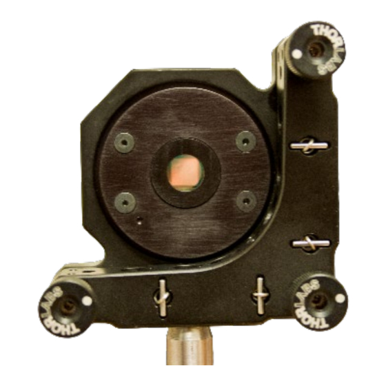
Section 5 - System Components Overview Front (Mirror) Side Rear (Cable) Side Figure 3 - Multi-DM in Customer-Supplied Thorlabs KS2 Kinematic Mirror Mount For installation and setup instructions of the DM enclosure see Section 7, Hardware Installation. Multi Driver Electronics The Multi-DM drive electronics provide 14-bit digital control of 140 high-voltage output channels. - Page 15 Multi-DM™ User Manual Section 5 - System Components Overview 5.3.1 Multi Driver Electronics Front Panel Figure 4 - Front Panel of Multi Driver Table 1 - Front Panel Connections Label Type Function USB 2.0 Mini-B Data connection to the control PC.
- Page 16 Press O to turn the Multi Driver off Table 4 - Rear Panel Connections Label Type Function J1-J4 DC-37 Female Outputs to the Multi-DM. 24VDC 6mm Coax 24VDC input from external power supply. High voltage output terminal. Use to measure Driver maximum voltage. 2mm Safety Sheathed Jack Ground terminal.
- Page 17 High voltages may be present. Only make connections with the Multi Driver off. DO NOT use the HV and GND connections unless specifically instructed to do so by a Boston Micromachines technical representative. HV and GND connectors: High voltages may be present.
-
Page 18: Sdk And Demonstration Software
By default, the DM and Multi Driver system ships with an SDK and applications for Microsoft Windows 64-bit operating systems. A Linux SDK is also available, contact Boston Micromachines for details. DMSDK-Setup-<version number>.exe, a self-executing installation program •... -
Page 19: Usb Cable
Multi-DM™ User Manual Section 5 - System Components Overview USB Cable A 6.5 ft (2 m) long USB 2.0 Type A male to Type Mini-B Male cable is supplied for connecting the Multi Driver to the control PC. ESD Wrist Strap An ESD wrist strap is supplied with all systems. -
Page 20: Bmc Sdk Software Installation
Multi-DM™ User Manual Section 6 - BMC SDK Software Installation BMC SDK Software Installation Make sure to complete the BMC SDK software installation per this section BEFORE attaching the Multi Driver. Installing the Multi Driver first can result in errors during installation. -
Page 21: Bmc Sdk Software Installation Instructions
Multi-DM™ User Manual Section 6 - BMC SDK Software Installation BMC SDK Software Installation Instructions The BMC SDK software consists of hardware and software drivers, GUI and command line applications to control the DM, and a full set of documentation. - Page 22 The BMC SDK - InstallShield Wizard - Readme Information dialog will display. 10. Read the information, then click Next. Note: To access the Readme Information text after installation, go the C:\Program Files\Boston Micromachines\Doc folder and locate the file ReadMe.txt. The BMC SDK - InstallShield Wizard - Ready to Install the Program dialog will display.
-
Page 23: Device-Specific File Installation
Multi-DM™ User Manual Section 6 - BMC SDK Software Installation Device-Specific File Installation There are two configuration files specific to the device you have that must be copied from the USB Flash Drive to specific folders in the BMC software folder. -
Page 24: Hardware Installation
If you are using a bench top optical setup, note that compatible optical mounts are listed in Section 5.7, Optical Mount (Optional, Customer-Supplied). Position the Multi Driver such that the cables from the Multi-DM can reach the rear panel and the cable from the PC can reach the front panel. - Page 25 Multi-DM™ User Manual Section 7 - Hardware Installation To install the Multi-DM hardware (continued): If the host PC is not powered up, power it up now. Allow the Windows operating system to fully start. Power up the Multi Driver by flipping the switch on the back of the unit.
-
Page 26: Verifying The Dm Installation
Multi-DM™ User Manual Section 8 - Verifying the DM Installation Verifying the DM Installation After installing the hardware and software: • The operation of the Driver and DM should be verified. • Any alignment(s) required by the optical system design can be performed Make sure to complete the BMC SDK software installation per Section 6 and the hardware installation per Section 7 BEFORE verifying the installation. -
Page 27: Verification Tools
8.1.1 Software Tools Boston Micromachines supplies two programs to directly control the DM. They are all installed by the SDK installation program. • DMShapes is a graphical user interface application that can load a shape from a text file and apply it to the DM, set the entire DM to a single value, or set actuators individually. - Page 28 8.1.3.1 The Multi Flat Setup Mirror The Multi Flat Setup Mirror Assembly is a form-fit compatible unit to the Multi-DM, where the active MEMS mirror is replaced with a simple static mirror. It can be used during setup and angular alignment to prevent shock and electrostatic discharge (ESD) damage to the sensitive MEMS element of the Multi-DM.
-
Page 29: Verifying The Installation
5. Visually verify the actuators all move together the same distance. How you verify this motion is dependent upon your application and optical setup. If technical assistance is necessary, contact Boston Micromachines. BMC Document Number: DOC-0009 Rev. 5.2 Page 26... - Page 30 Multi-DM™ User Manual Section 8 - Verifying the DM Installation 8.2.2 Verify the control of individual actuators 1. Turn on the Multi Driver, start the DMShapes application, and load the Profile for the Multi Driver and the DM. 2. Set all of the actuators to the top limit of their motion by doing one of the following: •...
-
Page 31: Performing Angular Alignment
Multi-DM™ User Manual Section 8 - Verifying the DM Installation Performing Angular Alignment Angular alignment refers to the direction of an axis perpendicular to the DM surface. Angular alignment requires the surface of the DM to be flat. This can be done... -
Page 32: Dmshapes Software Overview
Multi-DM™ User Manual Section 9 - DMShapes Software Overview DMShapes Software Overview This section is a reference for the graphical user interface application DMShapes. DMShapes is a graphical user interface application that can load a shape from a Command Map file, set the entire DM to a particular value (piston), or set actuators individually (poke) or sequentially (play). -
Page 33: The Dmshapes Window
Multi-DM™ User Manual Section 9 - DMShapes Software Overview The DMShapes Window Figure 7- DMShapes Window Title Bar Displays the program name and the serial number of the DM specified by the currently loaded Profile. This is the file name of the currently loaded Profile. - Page 34 Multi-DM™ User Manual Section 9 - DMShapes Software Overview Piston Displays a scale and a slider and allows changes to the entire array of actuators. For detailed information see Section 9.1.4, The DMShapes Piston. Status Bar Displays information on the last selected actuator and current piston setting. For detailed information see Section 9.1.5, The DMShapes Status Bar.
- Page 35 Multi-DM™ User Manual Section 9 - DMShapes Software Overview 9.1.2 The DMShapes Toolbar Note that the DM Toolbar can be floated, repositioned, and hidden. Icon Label Description Play Press to initiate a sequence to poke all actuators in sequence starting with actuator number 0 and ending with the highest numbered actuator.
- Page 36 Multi-DM™ User Manual Section 9 - DMShapes Software Overview The DMShapes Toolbar (continued) Icon Label Description Poke Press to apply the value of the current actuator to the actuator one Previous lower in number, i.e. poke it. The poked actuator then becomes the current selection.
- Page 37 Multi-DM™ User Manual Section 9 - DMShapes Software Overview The DMShapes Toolbar (continued) Icon Label Description Shape File Displays the name of the most recently applied Command Map List (unless one has been saved in the current session). When the program is first opened, the list box will default to show the first file in the Shapes folder even though it is not applied to the DM.
- Page 38 Surrounding mirror segments without actuators are not shown. Note that the display does not reference the orientation in the DM housing. For that orientation see Section 9.2, Multi-DM Mechanical Drawing. A grid delineating the actuators can be toggled on and off using the menu command Options >...
- Page 39 Multi-DM™ User Manual Section 9 - DMShapes Software Overview 9.1.4 The DMShapes Piston Area The Piston Area consists of a single control and a static display. • The Piston Slider controls the displacement of all of the DM actuators at once.
-
Page 40: Using The Dmshapes Application
Using the DMShapes Application 9.2.1 To Start DMShapes • On Windows: Click Start, then click All Programs, then click Boston Micromachines, then click DMShapes. • On Linux: From the Run dialog or your preferred terminal emulator, run “/opt/Boston Micromachines/bin/DMShapes” (with quotes) When the application opens: o The last specified Profile will be loaded. - Page 41 Multi-DM™ User Manual Section 9 - DMShapes Software Overview 9.2.4 To Change All Actuators • In the Piston Area, click and drag the slider to the desired value, then release. As you move the slider: o In the Actuator Map display, all actuators will change to the color for that value.
- Page 42 Multi-DM™ User Manual Section 9 - DMShapes Software Overview 9.2.7 To Poke All Actuators in Sequence • On the Toolbar, click the Play button. All actuators, starting with Actuator 0 and ending with the highest number actuator, will be poked in sequence...
- Page 43 Multi-DM™ User Manual Section 9 - DMShapes Software Overview 9.2.8 To Poke a Single Actuator Note that this command has no effect if the current and adjacent actuators have the same value. 1. Click to select an actuator. 2. Poke the next actuator in one of the following ways: To poke the actuator one higher in number, on the Toolbar click Poke Next.
- Page 44 9.2.10 To Find the Program Version • On the Menu Bar click Help, then click About. The DMShapes dialog will display with version information for the application and the SDK. Please provide this information when contacting Boston Micromachines for support. 9.2.11 To Close DMShapes •...
-
Page 45: Using Dmshapes With Multiple Dms
Each instance of DMShapes will connect to the Multi Driver and DM that is specified by the Multi Driver serial number in the Profile file that is loaded. For DMs purchased prior to January 1, 2018, contact Boston Micromachines to enable this functionality. To connect a single PC to multiple DMs: 1. -
Page 46: Reference Information
10. Reference Information This section contains the following topics: Section 10.1 Glossary Section 10.2 Help File Locations Section 10.3 Multi-DM Mechanical Drawing Section 10.4 Mirror Mapping for Multi Driver DRV00120-03 Section 10.5 DM Apertures Section 10.6 Multi Driver DRV00120-03 Mechanical Drawing Section 10.7 Multi Driver Auxiliary Output DE-9 Details... -
Page 47: Glossary
Actuator Map files have the file name extension .map and are stored in the Program Files\Boston Micromachines\Map folder. A DM of a particular size may have more than one Actuator Map corresponding to different packaging (e.g. cable pin out) configurations. - Page 48 A type of Command Map that drives the Deformable Mirror surface to a plane that is parallel to the silicon wafer base. Flat Maps for a DM are established by Boston Micromachines through interferometric analysis and are unique and custom to only that DM-Driver combination. Boston Micromachines typically supplies a Flat Map with each DM at 50% deflection for use in establishing a mirror surface for optical alignment and calibration.
- Page 49 PC interface type, and other settings. Profile file names contain the serial number of the DM device to which they apply. Profile files have the file name extension .dm and are stored in the Program Files\Boston Micromachines\Profiles folder. As installed, the Profiles directory contains generic profiles for demonstration purposes.
-
Page 50: Help File Locations
Multi-DM™ User Manual Section 10 - Reference Information 10.2 Help File Locations File Location Multi-DM System User Manual C:\Program Files\Boston Micromachines\Doc LabVIEW Getting Started C:\Program Files\Boston Micromachines\Doc MATLAB Getting Started C:\Program Files\Boston Micromachines\Doc Python Getting Started C:\Program Files\Boston Micromachines\Doc C/C++ Getting Started... -
Page 51: Multi-Dm Mechanical Drawing
Multi-DM™ User Manual Section 10 - Reference Information 10.3 Multi-DM Mechanical Drawing Figure 8 - 10.3 - Multi-DM Mechanical Drawing BMC Document Number: DOC-0009 Rev. 5.2 Page 48... -
Page 52: Mirror Mapping For Multi Driver Drv00120-03
Section 10 - Reference Information 10.4 Mirror Mapping for Multi Driver DRV00120-03 The actuator numbers on the Multi-DM are designated per Figure 9 - DM Actuator Map. • The radial orientation of the actuator array to the DM housing is indicated by the orientation mark on the mirror side of the housing. - Page 53 Multi-DM™ User Manual Section 10 - Reference Information Orientation Dimple Figure 9 - DM Actuator Map BMC Document Number: DOC-0009 Rev. 5.2 Page 50...
-
Page 54: Dm Apertures
Multi-DM™ User Manual Section 10 - Reference Information 10.5 DM Apertures In order to effectively use a deformable mirror, an understanding of the types of apertures, how they are calculated, and how they cover or are contained within the DM's reflective surface, is necessary. - Page 55 Multi-DM™ User Manual Section 10 - Reference Information 10.5.1 The Full Aperture The Full Aperture (FA) is the largest circular region that fits within the DM's reflective surface. The Full Aperture is what you see when looking directly at the DM, and is also known as the Unpowered Surface Figure.
- Page 56 Multi-DM™ User Manual Section 10 - Reference Information 10.5.2 The Active Aperture The Active Aperture (AA) is the largest circular region that fits within the displaceable controllable area of the DM surface. 10.5.2.1 The Active Aperture for Continuous DMs For continuous DMs, the Active Aperture is a circle inscribed within the outer controllable actuators.
- Page 57 Multi-DM™ User Manual Section 10 - Reference Information 10.5.3 The Recommended Optical Aperture The Recommended Optical Aperture (OA) is the largest circular region that fits within the displaceable FULLY controllable area of the DM surface. 10.5.3.1 Recommended Optical Aperture for Continuous DMs For continuous DMs, the Recommended Optical Aperture is a circle inscribed within the next actuator in from the outer controllable actuators.
-
Page 58: Multi Driver Drv00120-03 Mechanical Drawing
Multi-DM™ User Manual Section 10 - Reference Information 10.6 Multi Driver DRV00120-03 Mechanical Drawing Figure 10 - Multi Driver DRV00120-03 Mechanical Drawing BMC Document Number: DOC-0009 Rev. 5.2 Page 55... -
Page 59: Multi Driver Auxiliary Output De-9 Details
Utilizing these outputs requires a modified DM profile. To obtain this modified DM profile please contact Boston Micromachines. The pins are numbered as shown in Figure 11 - Multi Driver Front-Panel DE-9 Connector. - Page 60 Multi-DM™ User Manual Section 10 - Reference Information Mating Face View Figure 11 - Multi Driver Front-Panel DE-9 Connector Table 6 - Multi Driver Front-Panel DE-9 Outputs Description General-Purpose Host Output Frame Sync Out Low-Voltage Out A157 Low-Voltage Out A159...
-
Page 61: Multi Driver Dataflow And Error Detection
Multi-DM™ User Manual Section 10 - Reference Information 10.8 Multi Driver Dataflow and Error Detection To control the high voltage power supplies, the Multi Driver contains five (5) digital-to-analog converters (DACs), each with 32 channels, for a total of 160 channels. - Page 62 Multi-DM™ User Manual Section 10 - Reference Information Table 7 - ERROR LED Codes ERROR LED State Meaning Neither of the errors described below are present. Illuminated Solid The USB FIFO has gone empty before all 32 DAC channel groups have been received.
-
Page 63: System Performance
Multi-DM™ User Manual Section 10 - Reference Information 10.9 System Performance System performance, also referred to as system latency, is a measure of the time: • Starting when the host PC first starts sending DM data to the Driver • Ending when the DM mirror reaches its desired shape. - Page 64 Figure 12 - Kilo-DM Data Latency This graph is for a Kilo-DM using a Kilo-class Driver. Other DM sizes are similar. Boston Micromachines measures and publishes the Data Latency for each DM and Driver combination. BMC Document Number: DOC-0009 Rev. 5.2...
- Page 65 The Frame Rate is inversely proportional to the Data Latency time. Driver Comparison The Data Latency period \ Frame Rate frequency can be optimized by using a faster Driver and data connection combination. All Boston Micromachines DM models have both a standard and high speed driver available. Amplifier Slew Rate Another necessary term is Amplifier Slew Rate.
- Page 66 Multi-DM™ User Manual Section 10 - Reference Information Table 8 - Driver Specifications DM Type Driver Type Data Data Frame Rate Amplifier Connection Latency Slew Rate Multi-, Multi-ESF, Multi- USB 2.0 fixed 125μs 8 kHz 2V/μs Hex-111 Multi-, Multi-ESF X-class Camera under 5μs...
- Page 67 • Other applications need to detect a settled wavefront for analysis in the control loop. In these cases the Mechanical Response Time is most important. If you require assistance in analyzing your application, please contact Boston Micromachines. BMC Document Number: DOC-0009 Rev. 5.2...
-
Page 68: Deflection And Inter-Actuator Coupling
Multi-DM™ User Manual Section 10 - Reference Information 10.10 Deflection and Inter-Actuator Coupling For segmented DMs, the actual displacement is determined only by the magnitude of the command sent to the actuator. By their nature, segmented DMs have no inter-actuator coupling. - Page 69 30 Spinelli Place, Suite 103 Cambridge, MA 02138 T: 617 868 4178 | F: 617 868 7996 www.bostonmicromachines.com moreinfo@bostonmicromachines.com...
Need help?
Do you have a question about the Multi-DM and is the answer not in the manual?
Questions and answers