Table of Contents
Advertisement
Quick Links
Advertisement
Table of Contents
Troubleshooting

Summary of Contents for Magnum Dimensions MMSA Series
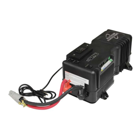
- Page 1 MMSA1012 Pure Sine Wave Inverter/Charger Owner’s Manual...
- Page 2 Thank you from all of us at Sensata Technologies for purchasing this MMSA1012 inverter/charger. The MMSA1012 is a product under the Magnum-Dimensions brand from Sensata Technologies. understand there are many purchasing options in the marketplace, and are pleased that you have decided on a Magnum product. This product was proudly assembled and tested in the United States in our Everett, Washington, facility.
- Page 3 Safety Information Record the unit’s model and serial number in case you need to provide this information in the future. Model: Serial Number: MMSA1012 Conventions used in this Manual Safety Symbols To reduce the risk of electrical shock, fi re, or other safety hazard, the following safety symbols have been placed throughout this manual to indicate dangerous and important safety instructions.
- Page 4 Safety Information • No AC or DC disconnects are provided as an integral part of this inverter. Both AC and DC disconnects must be provided as part of the system installation. • No overcurrent protection for the battery supply is provided. Overcurrent protection of the battery cables must be provided as part of the system installation.
-
Page 5: Table Of Contents
Table of Contents Introduction .............1 MMSA1012 Inverter/Charger ........1 How an Inverter/Charger Works ......... 1 Advantages of a Pure Sine Wave Inverter ....2 Appliances and Run Time .......... 2 Standard Features and Benefi ts ......... 2 Installation ..............8 Pre-Installation ............8 Locating and Mounting the Inverter ......10 DC Wiring ..............12 Connecting to the 3-Port Terminal Block .....18... - Page 6 List of Figures Figure 1-1, MMSA1012 Inverter ..........1 Figure 1-2, Top Side Features ..........4 Figure 1-3, Left Side Features ..........4 Figure 1-4, Right Side Features ..........5 Figure 1-5, Back Side Features ..........5 Figure 1-6, Front Side Features ..........6 Figure 1-7, MMSA1012 Inverter’s Anderson Connector ....
-
Page 7: Introduction
Introduction Introduction Congratulations on your purchase of an MMSA1012 inverter/charger. This product is designed to be powerful, yet simple to use, and will provide you with years of trouble-free use. Please read this chapter to familiarize yourself with the features and benefi... -
Page 8: Advantages Of A Pure Sine Wave Inverter
Introduction 1.2.1 Inverter Applications for Mobile Installations In mobile applications, an inverter/charger provides power to the AC loads using the energy stored in the batteries and recharges the batteries when shorepower or an onboard generator is available. Advantages of a Pure Sine Wave Inverter Today’s inverters come in two basic output waveforms: modifi... - Page 9 Introduction The MMSA1012 inverter/charger is equipped with the following: • Continuous 1000-watt output power and 50-amp charging (at 45°C, or 113°F) • Numerous protection features provide peace-of-mind operation and safe operation • AC transfer switch circuitry; allowing incoming AC power to continue to pass thru to power loads even if the inverter is off •...
-
Page 10: Figure 1-2, Top Side Features
Introduction Figure 1-2, Top Side Features AC Input Connection – a strain relief clamp with a 3 ft. standard plug-in power cord to provide AC power to the inverter. DC Ground Terminal – a ground connection used to tie the exposed chassis of the inverter to earth ground, or to the vehicle’s DC grounding system. -
Page 11: Figure 1-4, Right Side Features
Introduction Battery Temperature Sensor Connection – a RJ11 port that accepts the supplied remote Battery Temp Sensor (BTS) cable. Remote Connections – two RJ11 ports that allow two remote controls to be connected for adjusting/monitoring inverter and charger operation. Dual In-line Package (DIP) Switch – 10 individual slide switches that are used to determine the MMSA inverter/ charger’s operating parameters. -
Page 12: Figure 1-6, Front Side Features
Introduction Warning and Information Label – provides pertinent information for safely using the inverter. Positive DC Terminal – the inverter’s connection to the positive terminal on the battery bank. The MMSA1012 comes with one end of a red #2 AWG DC cable already connected to the inverter’s positive terminal (Figure 1-6), and the other end with an Anderson connector (SB175) attached (Figure 1-7). -
Page 13: Figure 1-8, Battery Temperature Sensor
Introduction 1.5.2 Battery Temperature Sensor A plug-in external Battery Temperature Sensor (BTS) is provided (Figure 1-8). When installed, the BTS automatically adjusts the battery charger’s BULK, ABSORB, and FLOAT voltage set-points based on temperature for better charging performance and longer battery life. -
Page 14: Installation
Installation Installation Pre-Installation Before installing the inverter, read the entire Installation section. The more thorough you plan in the beginning, the better your inverter needs will be met. WARNING: Installations should be performed by qualifi ed personnel, such as a licensed or certifi ed electrician. It is the installer’s responsibility to determine which safety codes apply and to ensure that all applicable installation requirements are followed. -
Page 15: Figure 2-1, Mmsa1012 Model Basic Installation Diagram
Installation AC IN Ground Anderson Connectors Disconnect Monitor Medical devices Overcurrent Device AC Loads Battery Bank Figure 2-1, MMSA1012 Model Basic Installation Diagram © 2015 Sensata Technologies... -
Page 16: Locating And Mounting The Inverter
Installation Locating and Mounting the Inverter WARNINGS: • Do not mount the inverter near any fl ammable or combustible fl uid or components. • Provide adequate clearance/ventilation to the inverter. • Mount only on a “non-combustible” surface. • Maximum ambient temperature around the inverter must not exceed 113°F (45°C) to meet power specifi... -
Page 17: Figure 2-2, Approved Mounting Orientations
Installation Close to the battery bank – As with any inverter, it should be located as close to the batteries as possible. Long DC wires tend to lose effi ciency and reduce the overall performance of an inverter. However, the unit should not be installed in the same compartment as the batteries or mounted where it will be exposed to gases produced by the batteries. -
Page 18: Dc Wiring
Installation Mounting holes x4 [¼” (.64 cm) diameter] 10.0" 16¾" (25.4 cm) (42.5 cm) R ESE T TE ST 6¾" (17.1 cm) 6¾" (17.1 cm) 7½" (19.1 cm) 8½" (21.6 cm) Figure 2-3, MMSA1012 Inverter Dimensions DC Wiring This section describes the inverter’s required DC wire sizes, the recommended disconnect/overcurrent protection, and how to make the DC connections to the inverter and the battery bank. - Page 19 Installation Refer to Figure 2-4 when connecting the DC wires to the battery. Also, consider the following requirements to ensure maximum performance: • The DC positive and negative cables connected to the inverter from the battery bank should be tied together with wire ties/ straps or electrical tape approximately every 6 inches (15.3 cm).
-
Page 20: Table 2-1, Recommended Dc Wire/Overcurrent Device
Installation If the distance from the inverter to the battery is >5 feet (1.5 m), the DC wire will need to be increased. Longer cable distances affect the performance of the inverter. See the lower part of Table 2-1 to determine the minimum DC wire size needed for various distances greater than 5 feet—based on your inverter model. - Page 21 Installation according to the size of DC cables being used, which means it is required to open before the cable reaches its maximum current carrying capability, thereby preventing a fi re. The NEC requires both overcurrent protection and a disconnect switch. Because batteries can deliver thousands of amps in an instant during a short, you are required to install a DC-rated fuse (or circuit breaker) that has a interrupt current rating (known as Amps Interrupting...
-
Page 22: Figure 2-4, Dc Cable To Battery Terminals
Installation Temperature sensor (BTS) DC cable with ring lug lock washer BATTERY battery terminal flat washer Verify that the DC cable lugs are flush bolt battery with the battery terminals. post Torque the battery terminals from 10 to 12 ft-lbs. Figure 2-4, DC Cable to Battery Terminals 2.3.5 Battery Bank Wiring WARNING: Lethal currents will be present if the positive... - Page 23 Installation CAUTION: Install batteries in a well-ventilated area. Batteries can produce explosive gasses. For compartment or enclosure installations, always vent batteries to the outside. 2.3.6 Inverter to Battery Bank Wiring WARNING: Ensure all sources of DC power (i.e., batteries) and AC power (utility/shorepower or AC generator) are de- energized (i.e., breakers opened, fuses removed) before proceeding.
-
Page 24: Connecting To The 3-Port Terminal Block
Installation 2. Connect a short wire (same rating as the DC wires) from one end of the fuse block to the positive terminal of the fi rst battery string (see Figure B-3). 3. Connect another short wire (same rating as the DC wires) from the other end of the fuse block to one end of the DC disconnect. -
Page 25: Remotes And Connections
Installation Aux DC Output (AUX) The Aux Output port provides auxiliary DC power from the battery for small loads not exceeding 20 amps (e.g., an interior lamp, backup camera, etc.). Whenever +12V is applied to the ignition (ICS) input, an internal relay closes and provides battery voltage (up to 20 amps) on the auxiliary (AUX) DC output. - Page 26 Installation ME-RC50/ME-ARC50 – Full feature remotes with backlit LCD display and LED indicators for inverter and charger status. Provide full menu access for easy selection and adjustment; come with a 50’ cable. The ME-RC50 and ME-ARC50 are used for many inverter models and have additional features that are not functional with the MMSA1012 inverter/charger.
-
Page 27: Figure 2-6, Mmsa1012 Accessory Connections
Installation Figure 2-6, MMSA1012 Accessory Connections © 2015 Sensata Technologies... -
Page 28: Gfci Breakers
Installation GFCI Breakers When installing a MMSA1012 inverter in an ambulance’s wiring system, a ground fault circuit interruption breaker (GFCI) may be installed to protect some branch circuits powered by the inverter. In compliance with UL standards, Sensata has tested the following GFCI’s and has found that they function properly when connected to the inverter’s AC output (there are others on the market that will work as well): Shock Sentry... -
Page 29: Functional Test
Installation Functional Test After all electrical connections to the inverter, batteries, AC source, and loads (using a sub-panel) have been completed, follow these steps to test the installation and the inverter’s operation. 1. Check the battery voltage and polarity before connecting the batteries to the inverter. -
Page 30: Setup
Setup Setup When the MMSA inverter/charger is not connected to a remote, the internal DIP switches (Figure 1-4, Item 11) are used to determine its operation. Info: When the MMSA is connected and networked with a remote, the remote can be used to set up and/or control the MMSA’s operation. - Page 31 Setup Switch 1: Use Inverter or Remote Settings When a remote control is connected to the MMSA, DIP Switch 1 determines whether the MMSA uses the inverter’s (DIP) settings or the connected remote’s settings to set up and/or control the MMSA’s operation.
- Page 32 Setup Info: If the inverter is on, supplying a +12VDC signal to the ICS terminal causes the 20A aux DC output voltage to be available on its output terminal—even if the ignition control switch is disabled (i.e., DIP Switch 2 is UP). Info: If DIP Switches 2 &...
- Page 33 Setup Switch 4: Search Mode The position of DIP Switch 4 allows you to enable the power-saving Search mode circuitry. Normally, the inverter is providing full AC voltage to the loads (DIP Switch 4 is UP). When Switch 4 is set DOWN, the Search mode feature is activated.
-
Page 34: Table 3-1, Battery Type To Charge Voltages
Setup AGM 1 Flooded AGM 2 Info: Voltages shown in Table 3-1 are based on the Battery Temperature Sensor (BTS) being disconnected, or at a temperature of 77°F (25°C). If the BTS is connected, the charge voltage changes based on the temperature around the BTS—to ensure the batteries receive the correct charge voltage even if they become cold or hot (see Section 1.5.2). - Page 35 Setup Switch 10: EQ Enable The position of DIP switch 10 allows an Equalize (EQ) charge to be started or stopped by the inverter. An EQ charge can be started by setting DIP switch DOWN or by using a connected remote. When an EQ charge starts, the position of DIP Switch 1 determines if the EQ charge settings (EQ voltage and time period) are dictated by the inverter settings or by the connected remote.
-
Page 36: Operation
Operation Operation This section discusses the MMSA inverter/charger’s ON/OFF switch and LED indicators, explains how the MMSA operates, provides information on the various remotes (and other accessories) that can be connected to the unit, and lists the inverter’s/remote’s default settings. Figure 4-1, Top Panel Power Switch and LED Indicators MMSA Top Panel Features The top panel (Figure 4-1) is used to turn the MMSA on/off and to... -
Page 37: Figure 4-2, Charge Status Indicators
Operation • INV LED blinks once per second – The inverter is connected to an external AC source (utility or generator power) and is in Standby mode. The inverter is ready to turn on and supply power to the loads if the external AC source is disconnected. •... - Page 38 Operation BULK ABSORB FLOAT Description (blue) (yellow) (green) Absorb Charge Stage – Charger is in Constant Voltage stage and begins after the bulk voltage is reached. The DC charging current will taper down in order to maintain the battery at the absorb target voltage Charger Back-off (in Absorb Charge Blink...
- Page 39 Operation Fault LED Indicator – Under normal operating conditions, the FAULT LED (red) indicator will be off. If there is a fault condition, this indicator illuminates to indicate that a fault condition has shut down the inverter. When the FAULT LED comes on, count the number of times it blinks (before turning off for two seconds) to determine the particular reason for the shutdown.
-
Page 40: Operating Modes
Operation Operating Modes The MMSA1012 inverter/charger has two normal operating routines. Inverter mode, which powers the loads using the batteries; and Standby mode, which transfers the incoming AC power (i.e., shorepower or a generator) to power the loads and to recharge the batteries. - Page 41 Operation 4.2.2 Standby Mode The MMSA1012 features an automatic transfer relay and an internal battery charger when operating in Standby mode. Standby mode begins whenever AC power (shorepower or generator) is connected to the inverter’s AC input. Once the AC voltage and frequency of the incoming AC power is within the AC input limits, an automatic AC transfer relay is activated.
-
Page 42: Figure 4-3, Automatic 4-Stage Charging Graph
Operation The automatic 4-stage charging process includes: Bulk Charging: This is the initial stage of charging. While bulk charging, the charger supplies the battery with constant current. The charger remains in bulk charge until the absorption charge voltage is achieved (14.6 VDC)* (per Battery Type selection**). Absorb Charging: This is the second charging stage and begins after the bulk voltage has been reached. -
Page 43: Protection Circuitry Operation
Operation Transfer time – While in Standby mode, the AC input is continually monitored. Whenever AC power falls below the VAC dropout voltage (80 VAC, default setting), the inverter automatically transfers back to Inverter mode with minimum interruption to your appliances—as long as the inverter is turned on. -
Page 44: Table 4-2, Inverter Battery Turn On/Off Levels
Operation • High Battery – In the event the battery voltage approaches the High Battery Cut Out (HBCO) level, the inverter will automatically shut down to prevent the inverter from supplying unregulated AC output voltage. The INV LED turns off when a high battery fault condition occurs. -
Page 45: Battery Temperature Sensor Operation
Operation Battery Temperature Sensor Operation The plug-in Battery Temperature Sensor (BTS) is used to determine the temperature around the batteries. This information allows the multi-stage battery charger to automatically adjust the battery charge voltages for optimum charging performance and longer battery life. -
Page 46: Summary Of Inverter/Dip Switch Settings
Operation Summary of Inverter/DIP Switch Settings Your MMSA1012 inverter uses default settings (established by DIP switch positions) that are adequate for most installations. However, if you determine that some of your operating parameters need to be changed, Sensata offers several remotes (Section 2.6) that allow you to customize the programming parameters of the inverter/ charger. -
Page 47: Maintenance & Troubleshooting
Maintenance & Troubleshooting Maintenance & Troubleshooting The following information is provided to help you keep your MMSA1012 inverter/charger in optimum operational condition. Recommended Inverter & Battery Care The MMSA1012 inverter is designed to provide you with years of trouble-free service. Even though there are no user-serviceable parts, it is recommended that every six months you perform the following maintenance steps to ensure optimum performance and extend the life of your batteries. -
Page 48: Table 5-1, Troubleshooting Guide
Maintenance & Troubleshooting Table 5-1, Troubleshooting Guide Symptom Possible Cause Recommended Solution Low Battery Battery voltage level Battery voltage too Voltage has dropped below low. Check fuses/ (status the Low Battery Cut circuit-breakers and indicator Out (LBCO) set- cable connections. blinks on 1 point for more than Check battery voltage... - Page 49 Maintenance & Troubleshooting Troubleshooting Guide, Cont. Symptom Possible Cause Recommended Solution Internal An internal fault To clear, perform a power fault (status detected. reset by removing DC indicator power to the inverter (see blinks on 5 Section 5.3). If the fault times every 3 does not clear, the unit secs)
-
Page 50: Performing An Inverter Reset
Maintenance & Troubleshooting Performing an Inverter Reset To perform an inverter reset (also known as a “soft reset”): 1. Remove all AC power (i.e., shorepower) to the inverter. 2. Press and hold the inverter’s ON/OFF pushbutton for approximately 10 seconds, or until all LEDs come on in sequence from the fi rst (INV) to the last (FAULT). -
Page 51: Specifi Cations
Specifi cations Specifi cations Table 6-1, MMSA1012 Specifi cations MODEL: MMSA1012 Inverter Specifi cations Input battery voltage 9 to 17 VDC Nominal AC output voltage 120 VAC +/– 5% Output frequency and accuracy 60 Hz +/– 0.1 Hz Total Harmonic Distortion <5% 1 msec surge current 38 AAC... -
Page 52: Appendix A - Optional Equipment & Accessories
Appendix A – Optional Equipment and Accessories Appendix A – Optional Equipment & Accessories The following components are available for use with the MMSA1012 inverter/charger. Some of these items are required depending upon the intended use of the inverter. Smart Battery Combiner The Smart Battery Combiner (ME-SBC ) is designed to monitor and charge a second battery using a portion of the current that... -
Page 53: Appendix B - Battery Information
Appendix B – Battery Information Appendix B – Battery Information Battery Bank Sizing The size of the battery bank determines how long the inverter can power the AC loads without recharging. The larger the battery bank, the longer the run time. Size your battery bank to the system’s AC load requirements and the length of time required to run the load from the batteries. -
Page 54: Figure B-2, Parallel Battery Wiring
Appendix B – Battery Information Parallel Wiring Wiring the batteries in parallel increases the total run time the batteries can operate the AC loads. A parallel connection combines overall battery capacity by the number of batteries in the string. Even though there are multiple batteries, the voltage remains the same. -
Page 55: Figure B-4, Battery Bank Wiring Examples
Appendix B – Battery Information overcurrent protection to 12 VDC inverter String 12 volts (total capacity = 100 AH) (12 VDC @ 100 AH) (100 AH) 12-volt battery bank (one string of one 12-volt battery) overcurrent protection to 12 VDC inverter Series String 6 volts... -
Page 56: Appendix C - Warranty/Service Information
Appendix C – Warranty & Service Information Appendix C – Warranty/Service Information Warranty Information Sensata Technologies warrants the MMSA1012 inverter/charger to be free from defects in material and workmanship that result in product failure during normal usage, according to the following terms and conditions: The limited warranty for the product extends for 24 months beginning from the product’s original date of purchase. -
Page 57: How To Receive Repair Service
Appendix C – Warranty & Service Information How to Receive Repair Service If your product requires warranty service or repair, contact either: • An authorized service center, at www.Magnum-Dimensions.com, • Sensata Technologies at: Telephone: 425-353-8833 Fax: 425-353-8390 Email: MagnumWarranty@Sensata.com If returning your product directly to Sensata for repair, you must: Return the unit in the original, or equivalent, shipping container Receive a Return Materials Authorization (RMA) number from the factory prior to the return of the product to Sensata for repair. - Page 58 Magnum-Dimensions Products Manufactured by: Sensata Technologies 2211 West Casino Rd. Everett, WA 98204 Phone: (425) 353-8833 Fax: (425) 353-8390 Web: www.Magnum-Dimensions.com MMSA1012 Owner’s Manual (PN: 64-0073 Rev A)
Need help?
Do you have a question about the MMSA Series and is the answer not in the manual?
Questions and answers