
Subscribe to Our Youtube Channel
Summary of Contents for ETT Olfactometer 2
- Page 1 ETT Olfactometer & ETTDirectControl The First Paradigm Manual and Tutorial Revision 2021.1...
- Page 2 © Emerging Tech Trans, LLC...
-
Page 3: Table Of Contents
Help..............................14 Connecting the Device .......................... 16 Before the first power up ........................16 ETT Olfactometer 2 ........................... 17 ETT Olfactometer S & ETT Olfactometer C ..................19 Prerequisites ............................21 The paradigm ............................ 21 Preparing the odorants ........................21 Connecting the tubing........................ - Page 4 Check valve layout in the odorant carrier ..................... 52 Typical air flow configuations ....................... 53 Configuration for multiple channels at once..................55 Setting up multiple channels within ETTDirectControl ................. 56 ETT EEG Trigger Interface.......................... 57 Hardware setup ............................ 57 System overview ..........................57 Software Setup ............................. 58 Prerequisites .............................
-
Page 5: The First Paradigm
1. This device is for research use only! 2. The main device / the actual ETT Olfactometer is not MRI compatible. 3. Only the ETT Odorant carrier, tubing, respiratory belt and the applicator/nose piece are MRI compatible and thus allowed into the magnet room. -
Page 6: Download
Figure 1 - Software support section on emergingtechtrans.com Download Once the fitting version / update track was chosen, a click on the download button will download the software. All installers automatically contain 32/64bit compatible installers. Figure 2 – Double-click on the downloaded executable to initiate the setup process Since ETTDirectControl requires device drivers, it will require to be installed with Administrator privileges (Figure 3). - Page 7 Figure 3 - For drivers and device access ETTDirectControl requires administrator privileges Once the necessary privileges are granted the installer will guide through each step. Please adjust the settings appropriately and click Next each time to progress (Figure 4). If multiple versions of ETTDirectControl are installed on the same machine, change the installation path.
- Page 8 Figure 5 - Adjust the installation path if necessary. Select .NET and USB drivers as they are needed for ETTDirectControl to operate (any needed extras will be automatically checked). Figure 6 - Define path of installation Figure 7 - Set Start Menu folder ©...
- Page 9 Figure 10 - Step through FTDI USB driver and .NET Framework 4 installers After successfully completing the installation and first starting the application, it is a good time to first plug the ETT Olfactometer into the USB port (consult Connecting the Device on page 16 if necessary). © Emerging Tech Trans, LLC...
-
Page 10: Software Overview
(Figure 11Figure 15). The number of listed buttons will adjust with the number of valves that your specific Olfactometer has. Figure 11 - Manual Mode with connected ETT Olfactometer 2 with active simulated respiratory signal. Valve 3 with the blue background color is opened. - Page 11 The paradigm designer is used for creating, testing and executing paradigms. It is divided into five sections, which generally represent the common workflow (as shown in Figure 12 and Figure 13). The following list of actions is associated with each of the sections: 0.
-
Page 12: Updater / Settings
Figure 12 - Sections of the Paradigm Designer in ETTDirectControl Figure 13 - Overlaid functional sections of Paradigm Designer The typical workflow would start at 0 and create and name or load a paradigm. Updater / Settings The Updater view is the easiest way to get access to new features. If the current update ring you are on receives an update for either ETTDirectControl or the connects device firmware, it will be shown here (Figure 14). - Page 13 Figure 14 - The Update and Settings view can be used to set basic parameters as well as checking for updates and switching Update Rings. In this case an update to version 1.0.2.3 would be advised. If advised by our support staff, there is also an option to update the device firmware to the latest version.
-
Page 14: Help
Help To get a general understanding of the features of this software and learn how to use ETTDirectControl for the most essential tasks, there are several options. Almost every button has a Tool Tip which will reveal further information upon hovering over the button for several seconds (Figure 15). - Page 15 Figure 17 - Example of a speech bubble when using the integrated help system Beyond using the listed features and our other online resources, please feel free to contact us if you have any further questions or problems: support@emeringtechtrans.com © Emerging Tech Trans, LLC...
-
Page 16: Connecting The Device
Figure 18). On all newer devices (2x) this is not necessary. Figure 18 - Please set the switch on the back panel of your ETT Olfactometer so that the small number on the slider is closest to your local AC power supply. -
Page 17: Ett Olfactometer 2
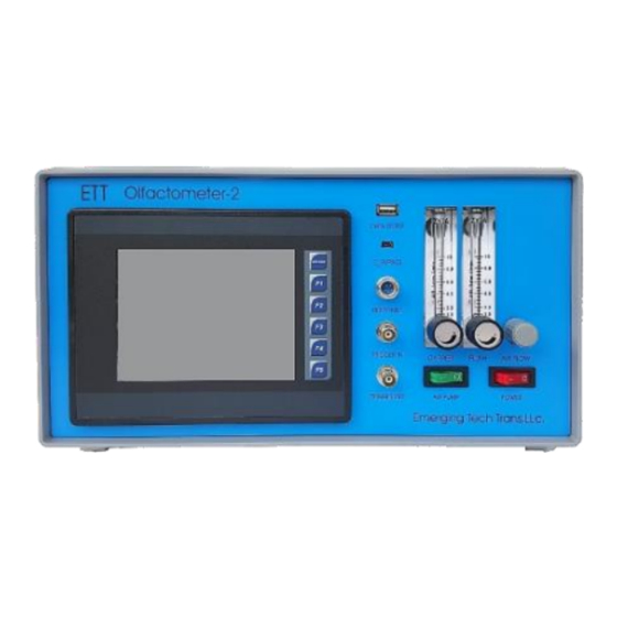
Figure 20 - On the ETT Olfactometer 2+ control is given to the PC via the PC CONTROL button on the main screen of the touchscreen OS. Figure 21 - Both olfactometers 2C and 2S need to be manually switched to PC control via the button on the front panel. - Page 18 Figure 22 – Olfactometer 2 front panel with USB port to PC (yellow), Respiratory response port (red) and TLL Trigger in port (green) Figure 23 - Main screen of the ETT Olfactometer 2 touchscreen operating system © Emerging Tech Trans, LLC...
-
Page 19: Ett Olfactometer S & Ett Olfactometer C
Figure 24 - Manual mode screen of touchscreen operating system of ETT Olfactometer 2. Valves can be switched by checking valves. Currently no control through connected PC Figure 25 - The ETT Olfactometer 2 screen is switched to external control from a connected PC and the ETTDirectControl software or the EPrime package. - Page 20 ETT Olfactometer 2 connected external TTL trigger signals as well as connected respiratory signals will also be transmitted to the connected software. Depending on the currently active context, an LED light will light up indicating MANUAL or PC control.
-
Page 21: Prerequisites
Prerequisites The paradigm This chapter will step through the creation of a first simple paradigm. For information beyond this description please consult the following paper (doi: 10.3233/JAD-141947). The paradigm presents each subject with 4 concentrations of Lavender (three each time, lowest to highest to avoid habituation). Each stimulus is 6 s long, followed by 30 s of odorless air. -
Page 22: Connecting The Tubing
Figure 29 - Distribution of odorant bottles in the odorant carrier. Connecting the tubing With your device, you will also receive a bound bundle of Teflon tubing (length 8 m) and a single line (length 2 m) that will connect the subject applicator mask to the odorant carrier output. To prevent damage and/or premature wear to both the quick release connectors as well as the Teflon tubing always make sure to push the tubing in straight without bending it until the tube is all the way into the connector. - Page 23 Figure 31 - Align channel indices of the device back panel with the labels of the odorant carrier Figure 32 - The latest version of the applicator guides a PTFE tube to the subjects’ nose. The flexible and easy to remove Loc-Line system can either be table mounted for EEG or coil mounted for fMRI studies.
-
Page 24: Flow Rate Adjustments
Figure 33 – On older devices the subject applicator mask is connected via the provided single tube Figure 34 - The latest version of the odorant carrier has a circular layout with the flush channel in the central location Replace kinked or damaged tubing to assure similar internal flow resistance between each channel and proper seal at the connector. -
Page 25: Creating A Simple Paradigm
panel of the Olfactometer has two columns to adjust the flow rate between stimulus periods that flow across the odorants (CARRIER) and during the baseline (FLUSH). On older devices without digital flow measurement, the total flow can be reduced via the AIR FLOW dial (Figure 35). - Page 26 Figure 36 - Create a new paradigm in ETTDirectControl Create a new folder to contain the future paradigm and name it Four Concentrations, then select that folder and ETTDirectControl will automatically generate a paradigm within that folder (Figure 37, Figure 38).
-
Page 27: Configuring An Olfactory Condition
The paradigm already contains a predefined device with six possible stimulus channels. If the user were to connect an ETT Olfactometer C or similar device with more possible channels this number will automatically adjust. Valve 1 is already preselected as the active channel. To the right of this tab, select the Group settings tab. - Page 28 While not used in this specific paradigm a respiratory trigger condition can be automatically tied to the onset of the valve open time of Channel 1. If set, the program will wait to proceed with opening valve 1 until an inhalation onset is detected on the connected respiratory belt. To add such a trigger condition or simply change the timing of the currently defined stimulus, click on the Channel visual in the group preview.
-
Page 29: Configuring The Visual Component
Figure 44 - The final composed view as defined in the previous figure, once added to the paradigm. Via the Loop selected... item in the context menu, it is possible to simplify the creation of pulsed or repetitive paradigms (Figure 45). It is also possible to multi select similar conditions to then loop them or delete them at once. - Page 30 Toggling the Subject Interface box in the bottom status bar, will bring up a non-full screen preview of the output of the current visual stimulus. Open the interface and changes will be represented as they occur (Figure 48). Figure 48 - Preview of subject interface. Define font size, screen id and full screen settings during paradigm execution in Paradigm Settings tab.
-
Page 31: Managing, Cloning And Adjusting Groups
In some cases, the end last visual stimulus is simply aligned with the longest defined olfactory stimulus. Then, checking the Extend to end checkbox next to the visual stimulus Duration textbox will automatically extend the duration of the visual stimulus to the end of the group (Figure 49 is equal to Figure 50 during paradigm execution). -
Page 32: Assembling Paradigm
Assembling paradigm After defining the four general conditions of this tutorial, it is time to assemble them into an actual paradigm. Groups are added via the Add to paradigm button in the Group settings tab as previously shown in Figure 53. Clicking this button will append the currently selected group to the end of the paradigm. -
Page 33: Triggered Start
Figure 56 - The Group randomizer with existing groups on the left allows to weight and exclude specific groups. The total number of trials determines the list of trials on the right. Trials can be added to the paradigm via the Append trial list to paradigm button. - Page 34 triggers are active (Figure 58) and especially when using respiratory signal based triggers that inhalation and exhalations onsets are detected properly (Figure 59). Figure 58 - Associated device to the previously defined group definitions. Multiple devices are supported! Figure 59 - All systems ready to go with simulated respiratory settings Figure 60 - The respiratory signal is also visualized on the top right corner of the paradigm designer incl.
- Page 35 While the paradigm is awaiting an external trigger, the External trigger label will flash red and gray (Figure 61). Figure 61 - Running paradigm awaiting an external TTL trigger. A click on the Manual Trigger button can progress the paradigm, if the physical trigger is not available during test runs (Figure 62).
-
Page 36: Inspecting The Data File
Start Paradigm button was pressed. Currently there are six file types generated for each paradigm run: 1. Triggers (Timing of external TTL, respiratory inhalation onsets, respiratory exhalation onsets, …) 2. ValveSwitches (Timing of ETT Olfactometer device activity) © Emerging Tech Trans, LLC... - Page 37 3. VisualQueue (Timing of visual stimuli as presented and context information like colors, text, image paths) 4. SubjectInput (Timing of Subject Interface keyboard inputs) © Emerging Tech Trans, LLC...
- Page 38 5. Respiration (Log of respiratory amplitude values) 6. TrialMarkers (Timing of specifically marked sections in paradigm to process later as conditions; also, custom trigger log and EEG interface if used) © Emerging Tech Trans, LLC...
-
Page 39: Using Triggers In Ettdirectcontrol
ETTDirectControl allows paradigms to be triggered by external TTL pulses. Once a BNC cable with a trigger source is connected to the device, and the ETT Olfactometer is connected to the computer, ETTDirectControl will automatically recognize the device. Once the device is connected to the software as shown in Figure 65, valves can be switched and sensors like external TTL trigger or respiratory information can be activated (Figure 66). -
Page 40: Respiratory Trigger
The belt must be connected to the provided receiver box, which is plugged into the RESPONSE port on the ETT Olfactometer front panel. Similarly, to the use of external TTL triggers, the respiratory signal needs to be enabled within the software. - Page 41 Figure 69 - Enabled respiratory sensor with preview of respiratory plot in ETTDirectControl software This field will also indicate if the subject is currently inhaling or exhaling. This information can be used to check if the location of the chest belt as well as belt tension are sufficient for the software to properly detect the subject’s respiratory cycle.
-
Page 42: Beyond Basics
Figure 71 - Visualization of predefined respiratory trigger (inhalation onset synchronization with valve open onset) in group settings via red RT. Figure 72 - Visualization of the paradigm during encounter of respiratory condition. The waiting block will flash green and gray until an inhalation onset is detected. - Page 43 (in this case a TTL pulse is received on the TRIGGER IN port of the ETT Olfactometer). The checkboxes Delay onset until and blocking both must be check in this case. Other possible trigger conditions can be chosen from a list in the drop-down menu.
- Page 44 valve open time of channel 1 of 4 seconds another valve close time of 20 seconds at the end Additionally, a visual queue is implemented as follows: 5 seconds white ‘+’ on black background during rest period 4 seconds white ‘x’ on black background during the stimulus presentation 5 seconds white ‘*’...
- Page 45 Figure 77 - Group setup in ETTDirectControl with device settings on top, visual queue below and trigger labels on the bottom on the blue background. Figure 78 - Configuration of an Exhalation onset trigger in the paradigm Right after the rest label, insert a respiratoryAnalogExhalationOnset from the triggers tab as described in Figure 78.
-
Page 46: Cleaning The Odorant Carrier
A cleaning bath will be required ii. The choice of detergent or solvent depends on the odorants used iii. Alcohol or non-odorous soap are typical For questions and advice consult emergingtechtrans.com in the support section or contact ETT at support@emergingtechtrans.com Cleaning the carrier top... - Page 47 4. Carefully unscrew all the screws from the bottle thread retainers and place them on a container 5. Place all bottle thread retainers (solid white rings) and bottle gaskets (clear silicone rings) from each channel in a cleaning bath 6. Each circle has two plugs to secure the back flow preventing valves (inlet and outlet to the glass odorant chamber).
- Page 48 7. Using tweezers take the small “clear” valve/gasket from each valve and store them in a separate container – There should be 2 per stimulus channel. Depending on the odorant carrier version there may be one or two additional valves in the flush channel 8.
- Page 49 9. Fill the cleaning bath with warm distilled water 10. Fill until all items are covered with water 11. Use the clear non-scented soap or alcohol and put a small amount in the cleaning bath 12. Place a watertight pump into the water or aggravate the water by hand – make sure it is fully immersed in the water ©...
-
Page 50: Cleaning The Bottles
Dump the distilled water and dry all parts before reassembly. Cleaning the bottles ETT Olfactometer glassware is dishwasher compatible. We recommend to handwash the lids contain a plastic threaded part and a Teflon insert to assure a tight odorless seal. - Page 51 alcohol depending on the intensity of the spill. It is advised to use the air of the olfactometer to blow tubing dry after washing before storing it. © Emerging Tech Trans, LLC...
-
Page 52: Odorant Flow Setup
Odorant flow setup Carrier Setup Check valve layout in the odorant carrier © Emerging Tech Trans, LLC... -
Page 53: Typical Air Flow Configuations
Typical air flow configuations © Emerging Tech Trans, LLC... - Page 54 © Emerging Tech Trans, LLC...
-
Page 55: Configuration For Multiple Channels At Once
Configuration for multiple channels at once © Emerging Tech Trans, LLC... -
Page 56: Setting Up Multiple Channels Within Ettdirectcontrol
Setting up multiple channels within ETTDirectControl © Emerging Tech Trans, LLC... -
Page 57: Ett Eeg Trigger Interface
EEG Trigger Interface can feed up to 50 different DIN labels into the EGI NetStation software. For this to work the Parallel Port of the ETT EEG Trigger needs to be plugged into the EGI AV DEVICE DIN Adapter. Figure 79 - Previous version of the EET EEG Interface Figure 80 - Current version of the ETT EEG Interface A full system overview can be seen in Figure 81. -
Page 58: Software Setup
After all hardware connections are made and all devices are turned on it is advisable to first assure that the ETT EEG Interface is recognized by the PC that has ETT Direct Control loaded. To see it working, one first has to get the EGI NetStation software ready. - Page 59 Activate the Events button in the main window to visualize DINS below Calibration and Marks as shown in Figure 83. At this point everything should be ready to continue with the setup in ETT Direct Control. Once that setup is completed submitted events will be marked as labeled DINS in the DIN track within the NetStation main window (Figure 84).
-
Page 60: Ett Direct Control
Paradigm Designer tab and then a switch to the EEG labels setup as shown in Figure 86. Figure 85 - ETT EEG Interface (EGI) in ETT Direct Control Manual Mode tab once successfully connected © Emerging Tech Trans, LLC... - Page 61 Figure 86 - First switch to the Paradigm Designer tab, then in the Group configuration section click Add / edit Triggers / Labels / EEG DINs Figure 87 - If the ETT EEG Interface is connected one can preview numerical DIN settings by typing the number and clicking the preview button To test basic functionality one can set the label in the EEG DINS Label textbox to a number between 1 and 63.
- Page 62 Figure 88 - Add a 1 s number presentation to the paradigm Set the Label to 1 and Duration to 1000 ms and click the Add to Group button (Figure 89). Figure 89 - Insert a 1s EEG DIN1 to the Group 1 that already contains a visual stimulus Hit F1 on your keyboard for a quick save.
- Page 63 EEG system. Since the EEG DINs have the same duration as the visual stimulus (general group length), when switching to the same group twice in a row the ETT EEG Interface will not send another DIN. This behavior is intentional for different scenarios, but to work around it, we can edit the duration of the DINs in each of the groups to be slightly shorter than the overall group length as shown in Figure 94.
- Page 64 Now it’s time to save the paradigm one more time (F1) and do a confirm the ETT EEG Interface is still connected in the Manual Mode tab. Then we can start the paradigm and observe the DINS in NetStation as shown in Figure 84.
Need help?
Do you have a question about the Olfactometer 2 and is the answer not in the manual?
Questions and answers