Advertisement
Quick Links
Model
A/V DOLBY DIGITAL RECEIVER/DVD PLAYER
PACKAGING PARTS LIST........................2
ESD WARNING....................................3
LEAKAGE TESTING...............................4
BASIC SPECIFICATIONS.......................5
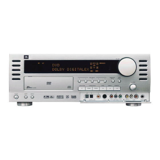
FRONT PANEL CONTROLS.....................8
INFORMATION DISPLAY.......................11
REAR PANEL CONNECTIONS...............12
REMOTE CONTROL FUNCTIONS..........16
REMOTE CONTROL II FUNCTIONS........24
GENERAL OPERATION.........................31
DISC CHANGER OPERATION................37
DVD/CD/MP3/VCD PLAYBACK OPERATION........41
TROUBLESHOOTING GUIDE.................46
CVR700
Cinema Vision
Service Manual
- CONTENTS -
JBL Consumer Products
250 Crossways Park Dr.
Woodbury, New York 11797
™
System
PROCESSOR RESET...........................47
UNIT EXPLODED VIEW.........................48
EXPLODED VIEW PARTS LIST.............49
DISASSEMBLY PROCEDURE...............50
BLOCK DIAGRAM...............................53
DC OFFSET ADJUSTMENT..................54
CINEMA VISION™ DIAGNOSTICS.........55
ELECTRICAL PARTS LIST...................59
SEMICONDUCTOR PINOUTS...............109
PCB DRAWINGS................................183
SCHEMATICS....................................197
WIRING DIAGRAM..............................213
Rev 0 4/2005
Advertisement

Related Manuals for JBL CVR700

Summary of Contents for JBL CVR700
- Page 1 REMOTE CONTROL FUNCTIONS……….16 ELECTRICAL PARTS LIST……………….59 REMOTE CONTROL II FUNCTIONS…..…24 SEMICONDUCTOR PINOUTS…………...109 GENERAL OPERATION………..………31 PCB DRAWINGS…………………………..183 DISC CHANGER OPERATION……….…...37 SCHEMATICS…………………..……….…197 DVD/CD/MP3/VCD PLAYBACK OPERATION…..…41 WIRING DIAGRAM..……………….………213 TROUBLESHOOTING GUIDE…..….…..…46 JBL Consumer Products 250 Crossways Park Dr. Woodbury, New York 11797 Rev 0 4/2005...
- Page 2 Cinemavision CVR700...
- Page 3 Cinemavision CVR700 Some semiconductor (solid state) devices can be damaged easily by static electricity. Such components commonly are called Electrostatically Sensitive (ES) Devices. Examples of typical ES devices are integrated circuits and some field effect transistors and semiconductor "chip" components.
- Page 4 Cinemavision CVR700 SAFETY PRECAUTIONS The following check should be performed for the continued protection of the customer and service technician. LEAKAGE CURRENT CHECK Measure leakage current to a known earth ground (water pipe, conduit, etc.) by connecting a leakage current tester...
- Page 5 Cinemavision CVR700 JBL CINEMA VISION TECHNICAL SPECIFICATIONS CVPD50 Display Size/Diagonal 50" (1270 mm); 16:9 Widescreen format Displayable Picture Size (W x H): 43-1/2" x 24-1/2" (932mm x 532mm) Resolution: 1366 x 768 pixels Viewing Angle: <160˚ Contrast Ratio: 3,000:1 Brightness:...
- Page 6 Cinemavision CVR700 Outputs: Composite (CVBS) Video: Rear Panel: 2 S-Video (Y/C): Rear Panel: 2 Component (Y/Pb/Pr or YUV): Rear Panel: 1 (Monitor Out) Analog Audio L/R: Rear Panel: 2 Digital Audio Coaxial: Rear Panel: 1 Digital Audio Optical: Front Panel: 1, Rear Panel: 1...
- Page 7 Cinemavision CVR700 CVR700 Amplifier Section Specifications 1. Output Power at 6 ohms, 1kHz, 10% / 0.5% T.H.D : Stereo Mode Front L/R (2 Channel Driven) 100W Output Power at 6 ohms, 1kHz, 10% / 0.5% T.H.D : Surround Mode Front L/R...
- Page 8 ^ Front-Panel Door 1 Main Power On/Off: Press this but- 3 Display Dimmer: Press this button to , the CVR700 will prompt you to enter ton to apply power to the CVR700. The reduce the brightness of the Information a disc number by pressing one of these Display Ô...
- Page 9 Memory Button @ again to store ton) the current track or chapter at 2x from the device to the CVR700. You will the station in the preset location displayed. speed. Press and hold again and release then need to press the Input Select to increase the scan speed to 4x.
- Page 10 NOTE: 6.1 and 7.1 digital modes are to the VIDEO INPUT line and available only when the appropriate digi- select it to configure the CVR700 to use tal bitstream is present. the video input you connected your ( Input Select Button: After you have device to.
- Page 11 C Programmed Play Indicators: The itself. You may need or wish to make The letters inside each box display the CVR700 is capable of playing discs in a manual adjustments to display the active input channels. For standard analog programmed order other than the order in...
- Page 12 ‚ NOTE: To make it easier to follow the instructions that refer to this illustration, a larger copy may be downloaded from the Product Support section for this product at www.jbl.com. 0 Back Surround Speaker Outputs D Composite and S-Video Monitor f Digital Recorder Coaxial Digital Audio (7.1-channel only)
- Page 13 Connect the black (–) termi- amplifier is used, connect this jack to Video Outputs: Connect the left/right nals on the CVR700 to the matching black the subwoofer amplifier input. Use a analog audio and composite or S-video negative (–) terminals for each side sur-...
- Page 14 This input is permanently assigned component video monitor outputs on the Component Video Monitor Output · to the Cable/Satellite source input. CVR700 are provided as a means of con- to the display. e DVI/Computer Coaxial Digital necting an auxiliary display only. On-...
- Page 15 Cinemavision CVR700 to this jack. The signal may be a Dolby damage to the device or to the CVR700, Digital signal, DTS signal or a standard which would not be covered under the PCM digital source. Do not connect the warranty.
- Page 16 Button a Disc Direct/PVR Live Button b Remote Menu/PIP Channel Up Button c DVD Setup/PIP On-Off/PIP Swap Button d JBL On Screen Library ™ /Favorite Button e Play Transport Control Button f Tuning Up/Forward Search Button g Channel/Slow Play Up/Down...
- Page 17 “page”, where the remote but- CVR700 receiver with disc changer and the CVPD50 screen. Before using the to select the control codes for the CVR700. tons are assigned control functions avail- remote, it is important to press the able for that specific purpose. For exam-...
- Page 18 I Set Button: This button is used to Line E, only stations with acceptable Button: Press this button when the tuner enter settings into the CVR700’s memory, is in use to directly enter a station’s fre- signal quality will be tuned when scan-...
- Page 19 When the tuner is in Manual/Mono mode, contain embedded information necessary button performs the Back function. For you may press and hold this button to for the CVR700 to make an automatic some PVRs/DVRs this button performs scan downward through the frequencies, adjustment. The available letterbox the Instant Replay function.
- Page 20 4:3 LTRBOX TO 16:9 – This mode is used Resize function has been turned off using Saver mode, in which a JBL logo will to adjust an image which is designed to the screen setup menus. See page 57 for appear to move around the screen.
- Page 21 PIP device to the next lower one. It In DVD/Main mode, this button accesses for an additional 7 seconds after any has no effect on the CVR700 or CVPD50. the JBL On Screen Library, which displays other button on the remote has been...
- Page 22 Cinemavision CVR700 When an optical player source, such as When used with optical sources, such as then either use the Preset Up/Down Buttons Jh to scroll to the desired the internal DVD changer, is in use, press the internal disc changer or an external...
- Page 23 DTS Neo:6 audio surround mode. when using the remote, and point the See page 62 for more information on the lens toward the CVR700 for the best available DTS Neo:6 options. results. In learning mode, the remote In the Screen mode, pressing this button receives IR codes to be learned through automatically adjusts the screen’s picture...
- Page 24 As it is a programmable, learning remote that is capable of controlling the source devices in your system, you will need to program it separately from the CVR700R2 remote with the codes for your other components. It is already preprogrammed at the factory to control your CVR700 and its internal disc changer, as well as the CVPD50 screen. Power On (All)
- Page 25 See page 64 for more selected source. In order to control for a given device. information. the CVR700 again, press the System Power On (All): Press this button Selector , and to control the to power on the CVR700, the CVPD50 or...
- Page 26 7: Test Tone: Press this button to activate of the Dolby Pro Logic II (available in This button performs the Letterbox func- the CVR700’s test tone that is used to cal- 5.1-channel systems) or IIx (available in tion, which enables you to adjust the ibrate speaker output levels.
- Page 27 36 38 Cinemavision CVR700 4:3 LTRBOX TO 16:9 – This mode is used which a JBL logo will appear to move connected to the Picture-in-Picture Composite Video Input a, pressing to adjust an image which is designed to around the screen. It is important to turn display a 16:9 movie on a 4:3 screen.
- Page 28 Status/TV/Video/PVR Play pressed or scaled in any way, but the Press this button a second time to store Button: Press it to display the CVR700 outer edges are cropped, sacrificing a your selection. To recall that station later, system’s status, or an external DVD...
- Page 29 System Selector: Press this button which displays on screen a thumbnail MP3 and WMA discs: 2x, 4x, 8x, 16x to select the control codes for the CVR700. image and description of each disc cur- See page 68 for more information on Screen Selector: Press this button rently loaded in the CVR700’s internal...
- Page 30 Cinemavision CVR700 Power Off (All): Press this button to place the CVR700 and CVPD50, or a selected device, in the Standby mode. Press and hold this button to place all devices, including the CVR700, the CVPD50 and any other products whose codes you have programmed into the remote, into the Standby mode.
- Page 31 CVPD50 will turn green. speakers and the headphone jack, but by unplugging the CVR700, and switching This will turn the CVR700 on and return it it will not affect any recording or dub- off the master power switch located on bing that may be in progress.
- Page 32 An optional, external RF demodulator is headphone’s plug is connected, the from that group if it is already in use, or required to use the CVR700 to listen to word HEADPHONE will scroll once the first available mode if you are cur-...
- Page 33 When a digital source is first detected, owner’s manual for your player to find and/or whether the digital signal is inter- the CVR700 will indicate the type of bit- the specific information to find the rupted (see Figure 41). stream being received by switching to the proper setting.
- Page 34 Cinemavision CVR700 feed to the CVR700 or to select between SURROUND menu. See page 47 for cessing modes such as Logic 7, to Dolby Digital or DTS. It is also possible information on using the menus to set greatly enhance downloaded or for the type of signal feed to change dur- this option.
- Page 35 Tuner Operation as the function of the Tuning/Preset To enter a station’s frequency directly, The CVR700’s tuner is capable of tuning Buttons 8. first select the AM or FM band as AM, FM and FM Stereo broadcast sta- desired be pressing the Tuner Button tions.
- Page 36 BACK TO MASTER MENU made and no further adjustments are and then press the Set Button s made for 5 seconds, the CVR700 will if you wish to go back to the main menu return to normal operation. to make other adjustments. If you have...
- Page 37 (see Figure 41). To load discs in the CVR700, first turn the not play on the CVR700. This does not CVR700 on by pressing the Main Power indicate any problem with the CVR700.
- Page 38 These messages are generated a 2-channel format. Figure 41 depicts that by the DVD changer section of the CVR700, a Dolby Digital 5.1-channel bitstream has and are separate from banner messages been detected.
- Page 39 Search mode, • While a disc is stopped, a Stop icon the CVR700 will begin to scan in the ) will appear on the left side of the Í opposite direction. Press the Play Upper Display Line H.
- Page 40 Repeat On, Title Repeat On and Repeat long as the DVD disc’s control program Off modes. does not force the CVR700 to return to a Audio CDs: The available conventional DVD menu in between. Repeat modes vary depending on whether the disc is in Play mode or Stop mode.
- Page 41 This feature is out of the control of the • Some DTS discs contain incorrect digi- VCD or JPEG discs. CVR700, as it is set by the disc’s inter- tal flags that may initially cause the nal programming. CVR700 to display incorrect information on the available surround modes or other features.
- Page 42 Status Bar will display the total number mode. The front-panel displays on the of tracks on the disc, and the total time CVR700 will remain lit to remind you of the disc. If the CD is playing, the first that the system is on.
- Page 43 Play Button !e discs may not play on the CVR700 even The front-panel display will only show the though they will work on a computer. number and the elapsed time of the track...
- Page 44 75. JPEG Playback The CVR700 is one of the few available DVD players that is capable of recogniz- ing JPEG still-image files and displaying them. When a disc containing JPEG files is loaded, the CD ROM Disc-Type Indicator A will light.
- Page 45 Note that if the disc was created with Playback place it in the CVR700 as you would do with any other CD or DVD disc. The unit Control (PBC – see below), it is not possi- takes a few seconds to read the disc’s...
- Page 46 CVR700 using the Main Power On/Off Switch 0, turn off the master power switch on the CVPD50 (depressed towards rear of unit), unplug the JBL Digital Link cable and unplug the AC power cords from both units. Then follow these steps in reverse order, and often the unit will function normally.
- Page 47 JBL Digital Link cable, and the power cords for both the CVR700 and the NOTE: Resetting the processor will erase CVPD50 and wait at least 3 minutes.
- Page 49 Cinemavision CVR700 CVR700 EXPLODED VIEW PARTS LIST...
- Page 50 Cinemavision CVR700...
- Page 51 Cinemavision CVR700 CVR700 DISASSEMBLY PROCEDURES <1> Top Cover(24) REMOVAL 1. Remove 13 screws(S2,S15) and then remove the Top Cover. <2> AV3+ BOX REMOVAL 1. Remove the Top Cover, referring to the previous step<1>. 2. Disconnect the FFC(12p) from connector(CN12) on the DVD PCB(49).
- Page 52 Cinemavision CVR700 3. Disconnect the FFC(CN24-13p) from Tuner Module(39). 4. Disconnect the FFC(CN23-25p) from connector(CN33) on the DIGITAL PCB(45). 5. Disconnect the FFC(CN11-25p) from connector(CN31) on the DIGITAL PCB(45). 6. Disconnect the FFC(CN12-17p) from connector(CN23) on the AMP PCB(48). 7. Disconnect the FFC(CN21-23p) from connector(CN11) on the AMP PCB(48).
- Page 53 Cinemavision CVR700...
- Page 54 Cinemavision CVR700...
- Page 55 Plasma-panel itself defect If any of the failures listed above are confirmed, the CVPD50 PDP needs to be returned to JBL as it is not field serviceable. Call 1-516-255-4525 for instructions. Possible malfunctions: DVD/Receiver CVR700 (which includes Video signal processing for the...
- Page 56 Video Control Box. Further testing should to be done. See next page for details. If the problem can be seen at the video monitor outputs of the CVR700, then the issue is not with the Shielded Video Control Box. Disconnect the Video Monitor/TV and redirect your attention to the picture on the CVPD50 Plasma Display.
- Page 57 Cinemavision CVR700 JBL Cinema Vision™ Diagnostics (cont’d) * Video signals should be connected directly to the CV700 Video inputs...
- Page 58 Cinemavision CVR700...
- Page 59 Cinemavision CVR700 CVR700 ELECTRICAL PARTS LIST Ref. Designator Part Number Description FRONT PCB CUP11680Y Capacitors C171 CCEA1CH221T CAP , ELECT 220UF 16V C175 CCEA1AH471T CAP , ELECT 470UF 10V C176 CCEA1AH471T CAP , ELECT 470UF 10V C177 HCBS1H223ZFT CAP , CERAMIC 0.022UF 50V Z...
- Page 60 Cinemavision CVR700 Ref. Designator Part Number Description FRONT PCB CUP11680Y D803 HVD1SS133MT DIODE 1SS133T-77 D881 HVD1SS133MT DIODE 1SS133T-77 D882 HVD1SS133MT DIODE 1SS133T-77 D883 HVD1SS133MT DIODE 1SS133T-77 D884 HVD1SS133MT DIODE 1SS133T-77 D891 HVD1SS133MT DIODE 1SS133T-77 D892 HVD1SS133MT DIODE 1SS133T-77 Q173 KVTKSC2785YT...
- Page 61 Cinemavision CVR700 Ref. Designator Part Number Description FRONT PCB CUP11680Y R843 CRD20TJ332T RES , CARBON 3.3K OHM 1/5W J R844 CRD20TJ100T RES , CARBON 10 OHM 1/5W J R845 CRD20TJ330T RES , CARBON 33 OHM 1/5W J R846 CRD20TJ330T RES , CARBON...
- Page 62 Cinemavision CVR700 Ref. Designator Part Number Description FRONT PCB CUP11680Y BN34 CWZCVR700BN34 SHIELD WIRE ASS'Y BN73 KJP15GB99ZM WAFER 35237(15PIN) BN75 KJP12GB99ZM CONNECTOR BN77 CWZCVR700BN77 SHIELD WIRE ASS'Y BN78 CWZCVR700BN78 SHIELD WIRE ASS'Y BN81 CWB1C004100EN WIRE ASS'Y BN88 CWB1C005150EW WIRE ASS'Y...
- Page 63 Cinemavision CVR700 Ref. Designator Part Number Description DVD LOADER (FRONT END) PCB Capacitors BC01 HCUS1H104ZF CAP , CHIP 0.1UF 50V Z BC02 HCUS1H104ZF CAP , CHIP 0.1UF 50V Z BC03 HCUS1H104ZF CAP , CHIP 0.1UF 50V Z BC04 HCUS1H104ZF CAP , CHIP 0.1UF 50V Z...
- Page 64 Cinemavision CVR700 Ref. Designator Part Number Description DVD LOADER (FRONT END) PCB C048 HCUS1H102KB CAP , CHIP , 1608 SIZE 0.001UF 50V K C049 HCUS1H391JA CAP , CHIP , 1608 SIZE 390PF 50V J C050 HCUS1H104ZF CAP , CHIP , 1608 SIZE 0.1UF 50V Z...
- Page 65 Cinemavision CVR700 Ref. Designator Part Number Description DVD LOADER (FRONT END) PCB D010 HVDRLS4148SR DIODE, SWITCHING, SMD TYPE RLS4148 TE-11 D011 HVDRLS4148SR DIODE, SWITCHING, SMD TYPE RLS4148 TE-11 D012 HVDRLS4148SR DIODE, SWITCHING, SMD TYPE RLS4148 TE-11 Q001 HVTKTA1664 TRANSISTOR , CHIP...
- Page 66 Cinemavision CVR700 Ref. Designator Part Number Description DVD LOADER (FRONT END) PCB R027 HRJ10DJ473T RES , CHIP (1/10W) , 47K OHM J 1608SIZE R029 HRJ10DJ103T RES , CHIP , 1608 SIZE 10K OHM , 1/10W 5% R030 HRJ10DJ102T RES , CHIP (1/10W) , 1K OHM J...
- Page 67 Cinemavision CVR700 Ref. Designator Part Number Description DVD LOADER (FRONT END) PCB Miscellaneous X001 BOX33868SC XTAL, CERAMIC RESONATOR (TDK) CCR33.86MXC7T J001 KJP07GB46ZM WAFER CN01 KJP24GB150ZG FFC CONNECTOR, 0.5MM, SMD TYPE GF055-24S-LSS CN02 KJP16GB149ZY FFC CONNECTOR 1MM, SMD TYPE 1008HR-16A00 CN03...
- Page 68 Cinemavision CVR700 Ref. Designator Part Number Description DVD MAIN PCB CUP11685Z C157 HCUS1E104ZF CAP , CHIP , 0.1UF ZF 1608 SIZE C158 HCUS1E104ZF CAP , CHIP , 0.1UF ZF 1608 SIZE C159 HCUS1E104ZF CAP , CHIP , 0.1UF ZF 1608 SIZE...
- Page 69 Cinemavision CVR700 Ref. Designator Part Number Description DVD MAIN PCB CUP11685Z C148 HCEC0JRV2101T CAP , CHIP ELECT 100UF/6.3V C149 HCUS1E104ZF CAP , CHIP , 0.1UF ZF 1608 SIZE C150 HCUS1E104ZF CAP , CHIP , 0.1UF ZF 1608 SIZE C151 HCUS1E104ZF CAP , CHIP , 0.1UF ZF...
- Page 70 Cinemavision CVR700 Ref. Designator Part Number Description DVD MAIN PCB CUP11685Z RP13 CRJ10DJ472T RES , CHIP , 1608 SIZE 4.7K OHM , 1/10W 5% RP15 CRJ10DJ472T RES , CHIP , 1608 SIZE 4.7K OHM , 1/10W 5% R124 CRJ10DJ330T RES , CHIP , 1608 SIZE...
- Page 71 Cinemavision CVR700 Ref. Designator Part Number Description DVD MAIN PCB CUP11685Z RN51 HRJ104DJ330T RES , 4ARRAY (1608*4) 33 OHM/1608*4 R101 CRJ10DJ472T RES , CHIP , 1608 SIZE 4.7K OHM , 1/10W 5% R102 CRJ10DJ472T RES , CHIP , 1608 SIZE 4.7K OHM , 1/10W 5%...
- Page 72 Cinemavision CVR700 Ref. Designator Part Number Description DVD MAIN PCB CUP11685Z R180 CRJ10DF82R5T RESISTOR 82.5OHM(1%) R181 CRJ10DF68R1T RESISITOR 68.1OHM(1%) R183 CRJ10DF68R1T RESISITOR 68.1OHM(1%) R185 CRJ10DJ472T RES , CHIP , 1608 SIZE 4.7K OHM , 1/10W 5% R186 CRJ10DJ271T RES , CHIP , 1608 SIZE...
- Page 73 Cinemavision CVR700 Ref. Designator Part Number Description 5CHANGER MECHANISM ASS'Y CJDMGX-F8002 HRL-CHE510 TRAVERSE UNIT ASS'Y RL-CHE510 KJC1A006 MAGENT ND QDR-3500(N-38) CKF1A277Z PANEL , REAR CVR700 CKL2A069H43 FOOT CMC1A221 PLATE , SHIELD CVR700 CMD1A521 FRAME , AV3 CVR700 CMD1A553 BRACKET , FAN...
- Page 74 Cinemavision CVR700 Ref. Designator Part Number Description DIGITAL PCB C392 HCUS1E104ZF CAP , CHIP , 0.1UF ZF 1608 SIZE C394 HCUS1H122KC CAP , CHIP , 1608 SIZE 0.0012UF 50V K C395 HCUS1H680JA CAP , CHIP , 1608 SIZE 68PF 50V J...
- Page 75 Cinemavision CVR700 Ref. Designator Part Number Description DIGITAL PCB C517 HCUS1E104ZF CAP , CHIP , 0.1UF ZF 1608 SIZE C518 HCUS1E104ZF CAP , CHIP , 0.1UF ZF 1608 SIZE C523 HCUS1E104ZF CAP , CHIP , 0.1UF ZF 1608 SIZE C524 HCUS1E104ZF CAP , CHIP , 0.1UF ZF...
- Page 76 Cinemavision CVR700 Ref. Designator Part Number Description DIGITAL PCB C356 CCEA1VH100T CAP , ELECT 10UF 35V C381 CCEA1CH220T CAP , ELECT 22UF 16V C383 CCEA1CH220T CAP , ELECT 22UF 16V C387 CCEA1CH220T CAP , ELECT 22UF 16V C389 CCEA1CH220T CAP , ELECT...
- Page 77 Cinemavision CVR700 Ref. Designator Part Number Description DIGITAL PCB Resistors L306 CRJ10DJ100T RES , CHIP , 1608 SIZE 10 OHM , 1/10W 5% RG01 CRJ10DJ4R7T RES , CHIP , 1608 SIZE 4.7 OHM , 1/10W 5% RG02 CRJ10DJ4R7T RES , CHIP , 1608 SIZE 4.7 OHM , 1/10W 5%...
- Page 78 Cinemavision CVR700 Ref. Designator Part Number Description DIGITAL PCB R352 CRJ10DJ101T RES , CHIP , 1608 SIZE 100 OHM , 1/10W 5% R353 CRJ10DJ101T RES , CHIP , 1608 SIZE 100 OHM , 1/10W 5% R354 CRJ10DJ101T RES , CHIP , 1608 SIZE...
- Page 79 Cinemavision CVR700 Ref. Designator Part Number Description DIGITAL PCB R441 CRJ10DJ332T RES , CHIP , 1608 SIZE 3.3K OHM , 1/10W 5% R442 CRJ10DJ332T RES , CHIP , 1608 SIZE 3.3K OHM , 1/10W 5% R443 CRJ10DJ103T RES , CHIP , 1608 SIZE...
- Page 80 Cinemavision CVR700 Ref. Designator Part Number Description DIGITAL PCB R511 CRJ10DJ104T RES , CHIP , 1608 SIZE 100K OHM , 1/10W 5% R512 CRJ10DJ104T RES , CHIP , 1608 SIZE 100K OHM , 1/10W 5% R513 CRJ10DJ104T RES , CHIP , 1608 SIZE...
- Page 81 Cinemavision CVR700 Ref. Designator Part Number Description DIGITAL PCB Miscellaneous BD32 HLZ9Z014Z CHIP , BEAD HU-1H4516-600JT BD33 HLZ9J003Z BEAD , FERRITE(CHIP) BLM21A121SPT BD34 HLZ9J003Z BEAD , FERRITE(CHIP) BLM21A121SPT L301 HLZ9J003Z BEAD , FERRITE(CHIP) BLM21A121SPT L302 HLZ9J003Z BEAD , FERRITE(CHIP) BLM21A121SPT...
- Page 82 Cinemavision CVR700 Ref. Designator Part Number Description INPUT PCB CUP11632Z C160 HCUS1H151JA CAP , CHIP , 150PF JA 1608 SIZE C161 HCUS1E104ZF CAP , CHIP , 0.1UF ZF 1608 SIZE C162 HCUS1E104ZF CAP , CHIP , 0.1UF ZF 1608 SIZE...
- Page 83 Cinemavision CVR700 Ref. Designator Part Number Description INPUT PCB CUP11632Z C248 CCEA1HH2R2T CAP , ELECT 2.2UF 50V C251 CCEA1EH220T CAP , ELECT 22UF/25V C252 CCEA1CH221T CAP , ELECT 220UF 16V C253 CCEA1CH221T CAP , ELECT 220UF 16V C259 CCEA1CH101T CAP , ELECT...
- Page 84 Cinemavision CVR700 Ref. Designator Part Number Description INPUT PCB CUP11632Z R111 CRJ10DJ471T RES , CHIP , 1608 SIZE 470 OHM , 1/10W 5% R112 CRJ10DJ471T RES , CHIP , 1608 SIZE 470 OHM , 1/10W 5% R113 CRJ10DJ224T RES , CHIP , 1608 SIZE...
- Page 85 Cinemavision CVR700 Ref. Designator Part Number Description INPUT PCB CUP11632Z R182 CRJ10DJ471T RES , CHIP , 1608 SIZE 470 OHM , 1/10W 5% R183 CRJ10DJ471T RES , CHIP , 1608 SIZE 470 OHM , 1/10W 5% R184 CRJ10DJ471T RES , CHIP , 1608 SIZE...
- Page 86 Cinemavision CVR700 Ref. Designator Part Number Description INPUT PCB CUP11632Z R269 CRJ10DJ103T RES , CHIP , 1608 SIZE 10K OHM , 1/10W 5% R270 CRJ10DJ103T RES , CHIP , 1608 SIZE 10K OHM , 1/10W 5% R271 CRJ10DJ103T RES , CHIP , 1608 SIZE...
- Page 87 Cinemavision CVR700 Ref. Designator Part Number Description VIDEO PCB C777 HCUS1H103KC CAP , CHIP , 1608 SIZE 0.01UF 50V K C780 HCUS1H101JA CAP , CHIP , 1608 SIZE 100PF 50V J C781 HCUS1H102KC CAP , CHIP , 1608 SIZE 0.001UF 50V K...
- Page 88 Cinemavision CVR700 Ref. Designator Part Number Description VIDEO PCB C716 HCUS1H221JA CAP , CHIP , 1608 SIZE 220PF 50V J C717 HCUS1H221JA CAP , CHIP , 1608 SIZE 220PF 50V J C718 HCUS1H221JA CAP , CHIP , 1608 SIZE 220PF 50V J...
- Page 89 Cinemavision CVR700 Ref. Designator Part Number Description VIDEO PCB C923 CCEA1VH100T CAP , ELECT 10UF 35V C924 CCEA1VH100T CAP , ELECT 10UF 35V C925 CCEA1AH471T CAP , ELECT 470UF 10V C926 CCEA1AH471T CAP , ELECT 470UF 10V C927 CCEA1AH471T CAP , ELECT...
- Page 90 Cinemavision CVR700 Ref. Designator Part Number Description VIDEO PCB Q976 HVTKRC102S TRANSISTOR , CHIP KRC102S Q973 HVTKSC2316YT TRANSISTOR KSC2316Y Resistors LF11 CRJ10DJ0R0T RES , CHIP , 1608 SIZE 0 OHM , 1/10W 5% LF12 CRJ10DJ0R0T RES , CHIP , 1608 SIZE...
- Page 91 Cinemavision CVR700 Ref. Designator Part Number Description VIDEO PCB R773 CRJ10DJ103T RES , CHIP , 1608 SIZE 10K OHM , 1/10W 5% R774 CRJ10DJ102T RES , CHIP , 1608 SIZE 1K OHM , 1/10W 5% R775 CRJ10DJ105T RES , CHIP , 1608 SIZE...
- Page 92 Cinemavision CVR700 Ref. Designator Part Number Description VIDEO PCB R865 CRJ10DF6810T RES , CHIP 681 OHM/1608/1% R866 CRJ10DF6810T RES , CHIP 681 OHM/1608/1% R867 CRJ10DF6810T RES , CHIP 681 OHM/1608/1% R868 CRJ10DF6810T RES , CHIP 681 OHM/1608/1% R869 CRJ10DF6810T RES , CHIP 681 OHM/1608/1%...
- Page 93 Cinemavision CVR700 Ref. Designator Part Number Description VIDEO PCB HWEUL1691-SXCU WIRE ASS'Y BN74 CWB2B015280EN WIRE ASS'Y BN75 CWB1C002400BM WIRE ASS'Y BN79 CWZCVR700BN79 SHIELD WIRE ASS'Y BN80 CWZCVR700BN80 SHIELD WIRE ASS'Y CN12 KJP06GA98ZM WAFER MOLEX35336-0610 CN13 KJP04GA01ZM WAFER MOLEX 5267-04A CN31...
- Page 94 Cinemavision CVR700 Ref. Designator Part Number Description AMP PCB C585 HCUS1H561JA CAP , CHIP , 1608 SIZE 560PF 50V J C586 HCUS1H561JA CAP , CHIP , 1608 SIZE 560PF 50V J C587 HCUS1H561JA CAP , CHIP , 1608 SIZE 560PF 50V J...
- Page 95 Cinemavision CVR700 Ref. Designator Part Number Description AMP PCB C770 HCUS1H473ZF CAP , CHIP , 1608 SIZE 0.047UF 50V Z C775 HCUS1H472KC CAP , CHIP , 1608 SIZE 0.0047UF 50V K C776 HCUS1H472KC CAP , CHIP , 1608 SIZE 0.0047UF 50V K...
- Page 96 Cinemavision CVR700 Ref. Designator Part Number Description AMP PCB C589 CCEA1VH100T CAP , ELECT 10UF 35V C590 CCEA1VH100T CAP , ELECT 10UF 35V C591 HCQI1H822JZT CAP , MYLAR 8200PF 50V J C592 HCQI1H822JZT CAP , MYLAR 8200PF 50V J C593...
- Page 97 Cinemavision CVR700 Ref. Designator Part Number Description AMP PCB C874 CCME2A154JXT CAP , METALLIZED FILM 100V / 0.15UF C881 CCEA1CKS100T CAP , ELECT 10UF 16V C882 CCEA1CKS100T CAP , ELECT 10UF 16V C885 CCEA1AH471T CAP , ELECT 470UF 10V C898...
- Page 98 Cinemavision CVR700 Ref. Designator Part Number Description AMP PCB D865 HVD1SR159-200 DIODE , SCHOTTKEY BARRIER 1A , 200V D866 HVD1SR159-200 DIODE , SCHOTTKEY BARRIER 1A , 200V D894 HVD1SS355T DIODE , CHIP 1SS355(0.1A , 80V) D897 HVD1SS355T DIODE , CHIP 1SS355(0.1A , 80V)
- Page 99 Cinemavision CVR700 Ref. Designator Part Number Description AMP PCB IC53 HVITP2150 I.C , DIGITAL AMP TP2150 IC63 HVITP2150 I.C , DIGITAL AMP TP2150 IC73 HVITP2150 I.C , DIGITAL AMP TP2150 IC78 HVINJM4556AL I.C , HEADPHONE NJM4556AL IC83 HVITP2150 I.C , DIGITAL AMP...
- Page 100 Cinemavision CVR700 Ref. Designator Part Number Description AMP PCB R577 CRJ10DJ103T RES , CHIP , 1608 SIZE 10K OHM , 1/10W 5% R578 CRJ10DJ103T RES , CHIP , 1608 SIZE 10K OHM , 1/10W 5% R580 CRJ10DJ100T RES , CHIP , 1608 SIZE...
- Page 101 Cinemavision CVR700 Ref. Designator Part Number Description AMP PCB R683 CRJ10DJ153T RES , CHIP , 1608 SIZE 15K OHM , 1/10W 5% R684 CRJ10DJ473T RES , CHIP , 1608 SIZE 47K OHM , 1/10W 5% R685 CRJ10DJ332T RES , CHIP , 1608 SIZE 3.3K OHM , 1/10W 5%...
- Page 102 Cinemavision CVR700 Ref. Designator Part Number Description AMP PCB R770 CRJ01HJR020T RES , CHIP , 6432 SIZE 0.02 OHM 1W 5% R775 CRJ10DJ203T RES , CHIP , 1608 SIZE 20K OHM , 1/10W 5% R776 CRJ10DJ203T RES , CHIP , 1608 SIZE...
- Page 103 Cinemavision CVR700 Ref. Designator Part Number Description AMP PCB R851 CRJ10DJ103T RES , CHIP , 1608 SIZE 10K OHM , 1/10W 5% R852 CRJ10DJ103T RES , CHIP , 1608 SIZE 10K OHM , 1/10W 5% R853 CRJ10DJ0R0T RES , CHIP , 1608 SIZE...
- Page 104 Cinemavision CVR700 Ref. Designator Part Number Description AMP PCB BD75 HLZ9Z014Z CHIP , BEAD HU-1H4516-600JT BD76 HLZ9Z014Z CHIP , BEAD HU-1H4516-600JT BD81 HLZ9Z018Z CHIP , BEAD HB-1M1608-601JT BD82 HLZ9Z018Z CHIP , BEAD HB-1M1608-601JT BD85 HLZ9Z014Z CHIP , BEAD HU-1H4516-600JT BD86...
- Page 105 Cinemavision CVR700 Ref. Designator Part Number Description SMPS PCB COP11686BSMPS C924 DA2GYE222MKCAP-Y 400VAC 222 "Y"(10mm) C926 WL 50V 2200 ㎌ 105'CCAP-EL 18Ø C928 WL 50V 2200 ㎌ 105'CCAP-EL 18Ø C929 DEI 50/100V 333JCAP-FILM 50/100V 333J C931 WL 50V 2200 ㎌ 105'CCAP-EL 18Ø...
- Page 106 Cinemavision CVR700 Ref. Designator Part Number Description SMPS PCB COP11686BSMPS U908 KA278R12CIC-REG TO-220 U909 FAN431IC-SHUNT 36V 100mA TO-92 1% U910 FAN431IC-SHUNT 36V 100mA TO-92 1% U911 KA7912IC-REG TO-220 U912 KA7905IC-REG TO-220 ZD91 1N5236BD-ZNER 0.5W 7.5V ZD92 1N5236BD-ZNER 0.5W 7.5V ZD93 1N5256BD-ZNER 0.5W 30V...
- Page 107 Cinemavision CVR700 Ref. Designator Part Number Description SMPS PCB COP11686BSMPS R950 1/8W 104-J R-C.F R970 1/8W 5K-J R-C.F R981 1/8W 5.3K-J R-C.F R982 1/8W 5.4K-J R-C.F R983 1/8W 5.5K-J R-C.F R984 2W 2.8K-J MINI R-C.F R986 1/8W 15K-J R-C.F R988 1/8W 5.6K-J...
- Page 108 Cinemavision CVR700 Ref. Designator Part Number Description SMPS PCB COP11686BSMPS KHR1A028 BUSHING , AC CORD KMC1A241 SHIELD CUSHION 10X25X10 KNW1A028 WASHER KGB1A139Z BADGE,JBL KHG1A050 RUBBER , CUSHION KHR301 CLAMPER KMC1A186 SHIELD, CUSHION KHE154 CLAMPER , ARM 0.12 CKC2B153S46 CABINET,TOP CTB3+8J...
- Page 109 Cinemavision CVR700 Transistor , Regulator BLOCK DIAGRAM TO-92M TO-92S TO-220F 1. Emitter 1. Emitter G : Gate 2. Collector 2. Collector D : Drain 3. Base 3. Base S : Source KRA102M KRC102M KSC2785Y KSA1175Y FQPF13N10 D-PAK TO-126 TO-92L 1: IN 1.
- Page 110 Cinemavision CVR700 PIN ASSIGNMENT (74HCU04AFN : IC13,IC39~IC42 ) LOGIC SYMBOL (10) (11) (13) (12) TRUTH TABLE...
- Page 111 Cinemavision CVR700 * 74VHCT32A : IC45 74VHCT32A ® QUAD 2-INPUT OR GATE PRELIMINARY DATA HIGH SPEED: t = 5 ns (TYP.) at V = 5V LOW POWER DISSIPATION: = 2 µA (MAX.) at T = 25 COMPATIBLE WITH TTL OUTPUTS: = 2V (MIN), V = 0.8V (MAX)
- Page 112 Cinemavision CVR700 74VHCT32A INPUT EQUIVALENT CIRCUIT PIN DESCRIPTION PIN No SYMBOL NAME AND FUNCT ION 1, 4, 9, 12 1A to 4A Data Inputs 2, 5, 10, 13 1B to 4B Data Inputs 3, 6, 8, 11 1Y to 4Y...
- Page 113 Cinemavision CVR700 ADV7195 < IC22> ADV7195 < IC22> * FUNCTIONAL BLOCK DIAGRAM SHARPNESS FILTER CONTROL ADV7195 ADAPTIVE CGMS FILTER CONTROL MACROVISION 11-BIT+ DAC A (Y) SYNC LUMA Y0–Y9 SSAF CHROMA TEST PATTERN 4:2:2 11-BIT GENERATOR DAC B Cr0–Cr9 4:4:4 DELAY...
- Page 114 Cinemavision CVR700 ADV7195 PIN FUNCTION DESCRIPTIONS Mnemonic Input/Output Function 1, 12 Digital Power Supply 2–11 Y0–Y9 10-bit progressive scan/HDTV input port for Y data. Input for G data when RGB data is input. 13, 52 Digital Ground 14–23 Cr0–Cr9 0-Bit Progressive Scan/HDTV Input Port for Color Data in 4:4:4 Input Mode.
- Page 115 Cinemavision CVR700 CS42528 : IC32...
- Page 116 Cinemavision CVR700...
- Page 117 Cinemavision CVR700...
- Page 118 Cinemavision CVR700 CS494003 : IC31...
- Page 119 Cinemavision CVR700 CS494003 BLOCK DIAGRAM SAI 0 Serial External Memor Compressed SAI 1 Audio Interface Digital SAI 2 Interface Interface SAI 3 Multi-Standard Farme DAO 0 Digital Shifter Audio Decoder DSP C Digital Audio Audio DAO 1 Programmable Input Output...
- Page 120 Cinemavision CVR700...
- Page 121 Cinemavision CVR700...
- Page 122 Cinemavision CVR700...
- Page 123 Cinemavision CVR700...
- Page 124 Cinemavision CVR700...
- Page 125 Cinemavision CVR700...
- Page 126 Cinemavision CVR700...
- Page 127 Cinemavision CVR700...
- Page 128 Cinemavision CVR700...
- Page 129 Cinemavision CVR700...
- Page 130 Cinemavision CVR700...
- Page 131 Cinemavision CVR700 CS4955 : IC23 BLOCK DIAGRAM...
- Page 132 Cinemavision CVR700...
- Page 133 Cinemavision CVR700...
- Page 134 Cinemavision CVR700 (ES6038 : IC11)
- Page 135 Cinemavision CVR700 PIN GEOGRAPHY...
- Page 136 Cinemavision CVR700...
- Page 137 Cinemavision CVR700 6 CH VIDEO DRIVER BH7862FS CTRAP COUT MUTE1 TEST MUTE1 TEST 1.5-6M MIXOUT MIXFB YTRAP CLAMP CLAMP PYIN YOUT PYTRAP PYOUT PYFB PbIN PbOUT PrIN N.C. MUTE2 MUTE2 PrOUT PrTRAP...
- Page 138 Cinemavision CVR700 HCF4053B : IC74 ANALOG MULTIPLEXERS-DEMULTIPLEXERS 4051B - SINGLE 8-CHANNEL 4052B - DIFFERENTIAL 4-CHANNEL 4053B - TRIPLE 2-CHANNEL QUIESCENT CURRENT SPECIFIED TO 20V FOR HCC DEVICE LOW ”ON” RESISTANCE : 125Ω (typ.) OVER (Plastic Package) (Ceramic Frit Seal Package) 15V p.p.
- Page 139 Cinemavision CVR700 4053B FUNCTIONAL DIAGRAMS AND TRUTH TABLES (continued) 4053 A or B Inhibit or C ax or bx or cx ay or by or cy None X = Don’t care. ABSOLUTE MAXIMUM RATINGS Symbol Parameter Value Unit Supply Voltage : HC C Types –...
- Page 140 Cinemavision CVR700 IC:54 HY57V161610ET-7 PIN CONFIGURATION DQ15 DQ15 DQ14 DQ14 VSSQ VSSQ DQ13 DQ13 DQ12 DQ12 VDDQ VDDQ DQ11 DQ11 DQ10 DQ10 VSSQ VSSQ 50pin TSOP II 50pin TSOP II VDDQ VDDQ VDDQ VDDQ 400mil x 825mil 400mil x 825mil...
- Page 141 Cinemavision CVR700 FUNCTIONAL BLOCK DIAGRAM 1Mx16 Synchronous DRAM Self Refresh Counter Refresh Refresh Interval Timer Counter 512Kx16 Bank 0 Address[0:10] Sense AMP & I/O gates Column Decoder Address Precharge Register Row Active BA(A11) Column Addr. Column Active Latch & Counter...
- Page 142 Cinemavision CVR700 HY57V641620HG(IC12:SDRAM) FUNCTIONAL BLOCK DIAGRAM 1Mbit x 4banks x 16 I/O Synchronous DRAM Self refresh logic Internal Row & timer counter 1Mx16 Bank 3 1Mx16 Bank 2 Row active Decoders 1Mx16 Bank 1 1Mx16 Bank 0 Memory Cell refresh...
- Page 143 Cinemavision CVR700 HY57V641620HG PI N CONF IGURA TION DQ 0 DQ 15 DQ 1 DQ 14 DQ 2 DQ 13 DQ 3 DQ 12 DQ 4 DQ 11 DQ 5 DQ 10 DQ 6 DQ 9 DQ 7 DQ 8...
- Page 144 Cinemavision CVR700 IC:24 HY57V643220C PIN CONFIGURATION D Q 0 D Q 1 5 D D Q S S Q D Q 1 D Q 1 4 D Q 2 D Q 1 3 S S Q D D Q D Q 3...
- Page 145 Cinemavision CVR700 HY57V643220C FUNCTIONAL BLOCK DIAGRAM 512Kbit x 4banks x 32 I/O Synchronous DRAM Self Refresh Logic Refresh & Timer Counter 512Kx32 Bank 3 512Kx32 Bank 2 Row Active Decoder 512Kx32 Bank 1 512Kx32 Bank 0 Memory Cell Array Column...
- Page 146 Cinemavision CVR700 *LC74781M : IC80 , IC81 LC74781, 74781M Pin Functions Pin No. Symbol Function Description Ground Ground connection (digital system ground) Xtal Used to connect the crystal oscillator and capacitor used to generate the internal Crystal oscillator connection synchronization signal, or to input an external clock (2fsc or 4fsc).
- Page 147 Cinemavision CVR700 LC74781, 74781M System Block Diagram...
- Page 148 Cinemavision CVR700 * LM1117-1.8 ( RG11 , RG13 , RG14) * LM1117-2.8 DS100919-4 Top View (RG12) TO-220 * LM1117-3.3 (RG15) DS100919-2 Top View TO-252 * BLOCK DIAGRAM * BLOCK DIAGRAM...
- Page 149 Cinemavision CVR700 M62429FP : IC88...
- Page 150 Cinemavision CVR700 M62446FP ( 6CH ELECTRONIC VOLUME : IC58 ) SYSTEM BLOCK DIAGRAM C in Cout SW in SWout SL in SLout volume SR in SRout BYPASS1 BYPASS2 tone L in Lout R in µ-com Rout interface volume LATCH DATA CLK...
- Page 151 Cinemavision CVR700 * MX29LV160ABT : IC16 44 SOP(500 mil) SYMBOL PIN NAME RESET A0~A19 Address Input Q0~Q14 Data Input/Output Q15/A-1 Q15(Word mode)/LSB addr(Byte mode) Chip Enable Input Write Enable Input BYTE Word/Byte Selection input BYTE RESET Hardware Reset Pin/Sector Protect Unlock...
- Page 152 Cinemavision CVR700 * BLOCK DIAGRAM WRITE CONTROL PROGRAM/ERASE STATE INPUT HIGH VOLTAGE MACHINE LOGIC RESET (WSM) STATE REGISTER ADDRESS FLASH ARRAY LATCH ARRAY A0-A19 SOURCE COMMAND DATA BUFFER Y-PASS GATE DECODER SENSE COMMAND DATA AMPLIFIER DATA LATCH PROGRAM DATA LATCH...
- Page 153 Cinemavision CVR700 FLASH MEMORY / MX29LV400TTC (IC33) PIN DESCRIPTION SYMBOL PIN NAME A0~A17 Address Input Q0~Q14 Data Input/Output Q15/A-1 Q15(Word mode)/LSB addr(Byte mode) Chip Enable Input Write Enable Input BYTE Word/Byte Selection input RESET Hardware Reset Pin/Sector Protect Unlock Output Enable Input...
- Page 154 Cinemavision CVR700 WRITE CONTROL PROGRAM/ERASE STATE INPUT HIGH VOLTAGE MACHINE LOGIC RESET (WSM) STATE REGISTER MX29LV400T/B ADDRESS FLASH LATCH ARRAY ARRAY A0-A17 SOURCE COMMAND DATA BUFFER Y-PASS GATE DECODER SENSE COMMAND DATA AMPLIFIER DATA LATCH PROGRAM DATA LATCH I/O BUFFER...
- Page 155 Cinemavision CVR700 NJM2068M (OP-AMP) : IC35~IC38 , IC52 , IC13~IC16...
- Page 156 Cinemavision CVR700...
- Page 157 Cinemavision CVR700 BLOCK DIAGAM (NJM2296M ) : IC71~IC73 Vin1 Vin2 Vout1 6.2dB dirver Vin3 6.2dB Vout2 dirver Vin4 6.2dB Vout3 dirver Vin5...
- Page 158 Cinemavision CVR700 * NJM2586 < IC25 > NJM2586L NJM2586M [BLOCK DIAGRAM]...
- Page 159 Cinemavision CVR700 NJU3718G * PIN CONFIGURATION * PIN DESCRIPTION FUNCTION Parallel Converts Data Output Terminals 8~13 Parallel Converts Data Output Terminals Serial Data Output Terminal Serial Data Output Terminal Clock Signal Input Terminal Strove Signal Input Terminal Clear Signal Input Terminal...
- Page 160 Cinemavision CVR700 * BLOCK DIAGRAM DATA Controller Circuit...
- Page 161 Cinemavision CVR700 PIN ASSIGNMENTS < IC51 > PCM1753/PCM1755 PCM1754 (TOP VIEW) (TOP VIEW) DATA DATA LRCK LRCK MUTE DGND DGND DEMP ZEROL/NA TEST ZEROR/ZEROA ZEROA AGND AGND FUNCTIONAL BLOCK DIAGRAM Audio LRCK Serial Output Amp DATA Port Low-Pass Filter 4y/8y...
- Page 162 Cinemavision CVR700 PCM1753 PCM1754 PCM1755 www.ti.com SLES092A – OCTOBER 2003 – REVISED AUGUST 2004 Terminal Functions TERMINAL DESCRIPTION DESCRIPTION NAME PCM1753/PCM1755 AGND – Analog ground Audio data bit clock input DATA Audio data digital input DGND – Digital ground LRCK...
- Page 163 Cinemavision CVR700 PRODUCT OVERVIEW S3C84BB/F84BB PIN ASSIGNMENT P2.7/TAOUT P8.0 P2.6/TACAP P8.1 P2.5/TACK P8.2 P2.4/TBPWM P8.3 P2.3/DAOUT P8.4/INT8 P2.2/SCK P8.5/INT9 P2.1/SI P6.0 P2.0/SO P6.1 P5.7 P6.2 P5.6/SDAT P6.3 P5.5/SCLK P6.4 S3C84BB/F84BB VDD1 VDD2 VSS1 VSS2 (80-QFP-1420C) XOUT P6.5 P6.6 TEST P6.7 P5.4...
- Page 164 Cinemavision CVR700 S3C84BB/F84BB PRODUCT OVERVIEW BLOCK DIAGRAM P0.0-P0.7 P1.0-P1.7 Port 0 Port 1 OSC/RESETB Port 2 P2.0-P2.7 RESETB I/O Port and Interrupt Control 8-Bit Basic Timer P2.7/TAOUT 8-Bit P2.6/TACAP Port 3 P3.0-P3.7 Timer P2.5/TACK /CounterA,B P2.4/TBOUT SAM88RC CPU 8-Bit P3.7/TCOUT0 Timer/ P3.6/TCOUT1...
- Page 165 Cinemavision CVR700 IC42 S3F84BB (FLASH MICOM) PIN No. NAME DESCRIPTION VFD_CS VFD STB port VFD_CLK VFD Clock port VFD_DATA VFD data port DATA UPDATE data port UPDATE clock port VDD 1 Power input port VSS 1 X OUT 10MHz Crystal Connection port...
- Page 166 Cinemavision CVR700 SiI 504 : IC21 BLOCK DIAGRAM Serial or Host Clock parallel bus Interface Generation Configuration Register Outputs Interlaced Video Deinterlace Video Progressive Video Input Video Output Input Processor Output Serial Audio Input Audio/ Video Serial Audio Output Sync...
- Page 167 Cinemavision CVR700 Silicon Image, Inc. SiI 504 SiI-DS-0045-D www.siimage.com 2.1 Pin Numbers Pin # Signal Name Pin # Signal Name Pin # Signal Name Pin # Signal Name Reserved Reserved Reserved HostAddr6 VDDCore Reserved VDDCore HostAddr7 GNDCore GNDCore GNDCore HostMode...
- Page 168 Cinemavision CVR700 Silicon Image, Inc. SiI 504 SiI-DS-0045-D www.siimage.com 2.2 Pinout Diagram HostAddr6 RSVD HostAddr7 RSVD HostMode GNDCore VDDCore MemClk HostClk GNDCore GNDcore VDDCore HostData15\VidInData19 MemData14 HostData14\VidInData18 MemData13 HostData13\VidInData17 MemData12 HostData12\VidInData16 MemData11 GNDCore MemData10 VDDCore GNDIO HostData11\VidInData15 MemData9 HostData10\VidInData14 MemData8...
- Page 169 Cinemavision CVR700 * SM5022A1H : IC55 SM5022 series PAD LAYOUT PINOUT (Unit : µ m) (Top View) (1000,800) (0,0) Chip size: 1.00 × 0.80 mm Chip thickness: 220 ± 30 µm Chip base: V level PIN DESCRIPTION and PAD DIMENSIONS P ad dimensions [µm]...
- Page 170 Cinemavision CVR700 SN74LVC157ADBR ( IC47 ) QUADRUPLE 2-LINE TO 1-LINE DATA SELECTORS/MULTIPLEXERS FUNCTION TABLE INPUTS OUTPUT LOGIC DIAGRAM(POSITIVE LOGIC) Pin numbers shown are for the D, DB, J, NS, PW, RGY, and W packages.
- Page 171 Cinemavision CVR700 ST92F124/F150/F250 - GENERAL DESCRIPTION Figure 8. ST92F124V1: Pin Configuration (Top-view TQFP100) 100 99 98 97 96 95 94 93 92 91 90 89 88 87 86 85 84 83 82 81 80 79 78 77 76 A20/P9.6 P8.4/AIN4 A21/P9.7...
- Page 172 Cinemavision CVR700 ST92F124/F150/F250 - GENERAL DESCRIPTION Figure 2. ST92F124V1: Architectural Block Diagram FLASH Ext. MEM. 128 Kbytes ADDRESS A[7:0] DATA D[7:0] Port0 3 TM 1 Kbyte Ext. MEM. A[10:8] ADDRESS Ports A[21:11] 4 Kbytes P0[7:0] P1[7:3] P1[2:0] Fully 256 bytes P2[7:0] Prog.
- Page 173 Cinemavision CVR700 I.C PIN DESCRIPTIONS (FLASH U-COM : ST92F124) : IC21 Function PIN No PIN Name Speaker On port SPK_ON AMP_MUTE AMP Mute Port Electronic Volume Data2 Port. EVOL_DA2 EVOL_CK2 Electronic Volume Clock2 Port. Micom update SOUT Micom update Micom update TX...
- Page 174 Cinemavision CVR700 DSP_RESET DSP reset port CD_RESET DIR+CODEC reset port DIR+CODEC chip selector port CD_CS HOST BUSY HINBSY DSP C Chip selector port DSP_C_CS DSP_AB_CS DSP AB Chip selector port INT_REQ DSP interrupt request port GND3 GND3 VDD3 Power Supply port3...
- Page 175 Cinemavision CVR700 TC9162AF (FUNCTION/INPUT : IC12) TC9162AF (FUNCTION/INPUT : IC 28) BLOCK DIAGRAM BLOCK DIAGRAM L-COM L-COM R-COM R-COM L-COM L-COM R-COM R-COM L-COM L-COM R-COM R-COM L-COM L-COM R-COM R-COM DATA DATA SHIFT REGISTER SHIFT REGISTER TC9164AF (FUNCTION/INPUT) : IC11...
- Page 176 Cinemavision CVR700...
- Page 177 Cinemavision CVR700...
- Page 178 Cinemavision CVR700...
- Page 179 Cinemavision CVR700 TC2001 Pinout ( IC52,62,72,82) 28-pin SOIC (Top View) BIASCAP INV2 FBKGND2 OAOUT2 DCMP BBM0 FBKOUT2 BBM1 VPWR M UTE FBKGND1 INV1 FBKOUT1 OAOUT1 HM UTE AGND VPPSENSE OVRLDB VNNSENSE OCD1 OCD2 TP2150 Pinout ( IC53,63,73,83 ) 64-pin LQFP...
- Page 180 Cinemavision CVR700 TC2001 Audio Signal Processor Pin Descriptions ( IC52,62,72,82) Function Description BIASCAP Bandgap reference times two (typically 2.5VDC). Used to set the common mode voltage for the input op amps. This pin is not capable of driving external circuitry.
- Page 181 Cinemavision CVR700 TP2150 Pin Description ( IC53,63,73,83 ) Function Description AGND Analog ground. 5V power supply input. OCD1 Over-current threshold output (Channel 1) Soft startup for VN10 controller, this pin should be tied to V5 OCD2 Over-current threshold output (Channel 2)
- Page 182 Cinemavision CVR700 74HC151 : IC34 Functional Diagram 16 VCC 15 I3 14 I4 13 I6 12 I7 11 S0 10 S1 9 S2 GND = 8 = 16 TRUTH TABLE SELECT INPUTS DATA INPUTS ENABLE OUTPUT NOTE: H = High Voltage Level, L = Low Voltage Level, X = Don’t Care...
- Page 183 Cinemavision CVR700 AMP BOARD(BOTTOM SIDE)
- Page 184 Cinemavision CVR700 AMP BOARD(TOP SIDE)
- Page 185 Cinemavision CVR700 DIGITAL BOARD(BOTTOM SIDE)
- Page 186 Cinemavision CVR700 DIGITAL BOARD(TOP SIDE)
- Page 187 Cinemavision CVR700 DVD F_E BOARD(TOP SIDE)
- Page 188 Cinemavision CVR700 DVD F_E BOARD(BOTTOM SIDE)
- Page 189 Cinemavision CVR700 DVD MPEG BOARD(BOTTOM SIDE)
- Page 190 Cinemavision CVR700 DVD MPEG BOARD(TOP SIDE)
- Page 191 Cinemavision CVR700 FRONT BOARD...
- Page 192 Cinemavision CVR700 MAIN BOARD(BOTTOM SIDE)
- Page 193 Cinemavision CVR700 MAIN BOARD(TOP SIDE)
- Page 194 Cinemavision CVR700 SMPS BOARD...
- Page 195 Cinemavision CVR700 VIDEO BOARD (TOP SIDE)
- Page 196 Cinemavision CVR700 VIDEO BOARD (BOTTOM SIDE)
- Page 197 Cinemavision CVR700 AMP BOARD #1...
- Page 198 Cinemavision CVR700 AMP BOARD #2...
- Page 199 Cinemavision CVR700 DIGITAL BOARD...
- Page 200 Cinemavision CVR700 DVD LOADER (FRONT END) #1...
- Page 201 Cinemavision CVR700 DVD LOADER (FRONT END) #2...
- Page 202 DVD LOADER (FRONT END) #3 Cinemavision CVR700...
- Page 203 DVD LOADER (FRONT END) #4 Cinemavision CVR700...
- Page 204 DVD LOADER (FRONT END) #5 Cinemavision CVR700...
- Page 205 Cinemavision CVR700 DVD LOADER (FRONT END) #6...
- Page 206 DVD MPEG BOARD #1 Cinemavision CVR700...
- Page 207 Cinemavision CVR700 DVD MPEG BOARD #2...
- Page 208 FRONT BOARD Cinemavision CVR700...
- Page 209 MAIN BOARD (INPUT PART) Cinemavision CVR700...
- Page 210 Cinemavision CVR700 MAIN BOARD (MCU PART)
- Page 211 Cinemavision CVR700 SMPS BOARD...
- Page 212 Cinemavision CVR700 VIDEO BOARD...
- Page 213 Cinemavision CVR700...
Need help?
Do you have a question about the CVR700 and is the answer not in the manual?
Questions and answers