
Summary of Contents for Gopel Electronic basicCON 4115
- Page 1 4115 LVDS Frame Generator User Manual (Translation of Original docu) Document version 1.5 GOEPEL electronic GmbH Goeschwitzer Str. 58/60 •D-07745 Jena + 49-3641-6896-597 • ats_support@goepel.com • www.goepel.com...
- Page 2 © 2014 GOEPEL electronic GmbH. All rights reserved. The software described in this manual as well as the manual itself are supplied under license and may be used or copied only in accordance with the terms of the license. The customer may make one copy of the software for safety purposes. The contents of the manual is subject to change without prior notice and is supplied for information only.
-
Page 3: Table Of Contents
2.4.2 Assembly ............... 2-7 2.4.3 Power supply ............2-8 2.4.4 Addressing ............. 2-8 2.4.5 LVDS Interface ............2-9 2.4.6 LED Indication ............2-11 ............. 2-12 ELIVERY OTES SOFTWARE ..............3-1 G-API P ............3-1 ROGRAMMING basicCON 4115 – User Manual... -
Page 5: Installation
Installation Installation Hardware Installation Generally hardware installation for basicCON 4115 means connecting the cables for USB (or RS232), LVDS and power supply (see Hardware). Please make absolutely certain that all of the installation procedures are carried out with your system switched off. -
Page 6: River Nstallation
Please note that the Device Manager shows ALL USB controllers supported by this driver. If required, your basicCON 4115 can also be controlled via the serial RS232 interface. Then, the G-USB driver setup is not necessary, but the device can NOT be operated by the G-API. -
Page 7: Hardware
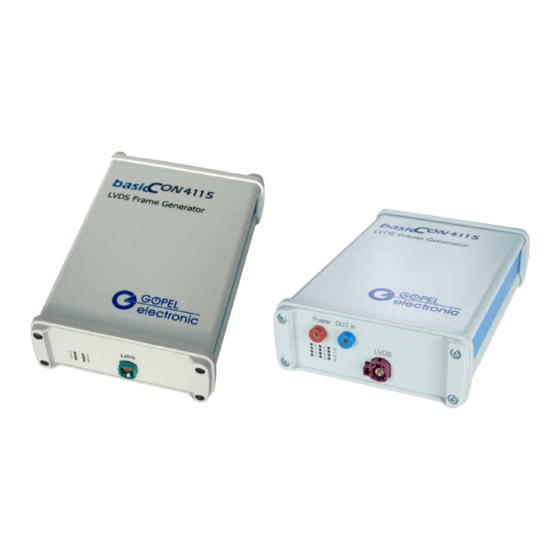
(if required also RS232 is possible), while the LVDS Frame Generator itself is operated via PC software. The basicCON 4115 with the INAP375T APIX 2 transmitter can also receive control data via uplink data streams (but no RGB or audio signals). - Page 8 APIX 2 version four LEDs (presently two of them without any function) for the status display of the APIX 2 link (see Indication): Figure 2-2: basicCON 4115/ AP IX 2 basicCON 4115 – User Manual...
- Page 9 Hardware At the device’s rear side you find the following connections: Figure 2-3: basicCON 4115 – R ear view Banana sockets for power supply (left) ¨ DC socket for the AC adaptor plug (center) ¨ RS232 socket for the serial interface (top right) ¨...
-
Page 10: Technical Specification
Ω LVDS LVDS data rate 3000 Mbit/s Depends on the LVDS transmitter Please use the supplied USB cable to connect a basicCON 4115 stand-alone device to the PC’s USB interface. Other cables may be inapplicable. basicCON 4115 – User Manual... -
Page 11: Display Timings
Hardware Display Timings To control different displays, the basicCON 4115 LVDS Framegenerator generates signals according to the patterns shown in Figure 2-4 and Figure 2-5. The Timing values can be parameterized according to Table1. By the LVDS serializer this data is serialized and transferred to the display. - Page 12 Only during the H_BLANK_WIDTH time control data is sampled. That means, that H_FRONT_PORCH + H_SYNC_WIDTH must be less than H_BLANK_WIDTH. V_ BLANK_WIDTH must be greater than V_FRONT_PORCH + V_SYNC_WIDTH otherwise the image is read wrongly from the memory. basicCON 4115 – User Manual...
-
Page 13: Construction
APIX2 link 2.4.2 Assembly For all basicCON 4115 variants (except of the APIX 2 variant), the Serializer and the LVDS connector (for the variant for APIX 1 also the connector for the DUT power supply) are mounted on the LVDS top- board. -
Page 14: Power Supply
This power supply is effected via the two Power DUT In banana sockets (red = plus/ blue = minus), located left on the front panel. 2.4.4 Addressing Addressing several basicCON 4115 devices is effected exclusively via their serial numbers: The device with the LEAST serial number has always device number 1. -
Page 15: Lvds Interface
2 – LVDS Clk– 3 – GND 4 – GND 5 – LVDS 0+ 6 – LVDS 0– 7 – LVDS 1+ 8 – LVDS 1– 9 – LVDS 2+ 10 – LVDS 2– Shield – GND basicCON 4115 – User Manual... - Page 16 For the connection, use only STP cables with 100Ω impedance and corresponding connector. When connecting the cables, please pay attention to connect the wire pairs always to LVDS+ and LVDS– each. 2-10 basicCON 4115 – User Manual...
-
Page 17: Led Indication
Hardware 2.4.6 LED The LEDs 1..8 arranged near to the LVDS connector show the current operating state of the basicCON 4115 Frame Generator, LED 9 and Indication LED 10 (if applicable) show the transfer status of the APIX 2 link: LEDs 4 ¡... -
Page 18: Delivery Notes
Hardware Delivery Notes The basicCON 4115 LVDS Frame Generator can be delivered in the following variants with the following accessories (please specify the pixel clock frequency with your order): basicCON 4115.10 with MAX9247 top-board ¨ basicCON 4115.20 with MAX9209 top-board ¨... -
Page 19: Software
Please consult the G-API documentation for further information. This documentation and the installation software are located in the G-API folder of the supplied Product CD. basicCON 4115 – User Manual... - Page 21 Banana females ..... 2-8 DC Socket...... 2-8 For DUT ......2-8 G-API ....... 3-1 RS232 ....1-2, 2-1, 2-3 Hardware Explorer ..... 3-1 Serializer Exchange ...... 2-7 Types ......2-7 SPI ........2-1 STP Cable ....... 2-10 basicCON 4115 – User Manual...
Need help?
Do you have a question about the basicCON 4115 and is the answer not in the manual?
Questions and answers