Table of Contents
Advertisement
Quick Links
Advertisement
Table of Contents

Related Manuals for CD CDC1-B

Summary of Contents for CD CDC1-B
- Page 1 CDC1-B Specification Cloud drive intelligent technology Co.,Ltd...
-
Page 2: Table Of Contents
Cloud drive intelligent technology Co.,Ltd Contents 1.About the user manual ....................... 2 2.Material and external dimensions ....................2 Real product and dimension figure :(unit: mm) ................2 3.Function summary ........................3 4.Button fuunction ........................6 5.Installation instructions ......................6 6.Normal operation ........................7 (1). -
Page 3: About The User Manual
Cloud drive intelligent technology Co.,Ltd 1.About the user manual Dear users, To ensure better performance of your ebike, please read through the CDC1 instruction carefully before using it. We will inform you of all the details, including the installation and function setting of the display with the most concise words. Meanwhile, the specification will also help you to solve possible malfunction. -
Page 4: Function Summary
Cloud drive intelligent technology Co.,Ltd Figure 2 3. Function summary CDC1 is a Multifunctional display that integrated throttle function. The same display can match 24v, 36v, 48v battery. At the same time integrated with 24V, 36V and 48V front lights. With another product CDBL_C of our company will greatly simplify the handlebar cable. - Page 5 Cloud drive intelligent technology Co.,Ltd ◆ 6Km/h implementation mode ◆ Battery capacity indication ◆ Error code definition ◆ Kilometers or miles unit selection ◆ Password setting ◆ Wheel diameter selection ◆ Voltage selection Figure 3-1 Page of 24 Jim@clouddrive.tech Jim:(+86)18221324155...
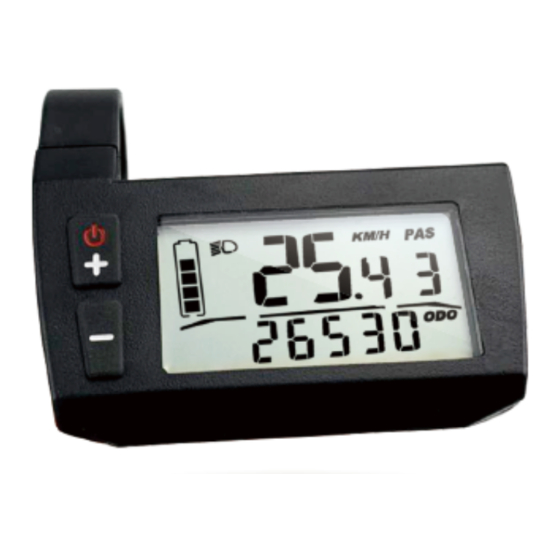
- Page 6 Cloud drive intelligent technology Co.,Ltd Display all ( figure 3-2 ) Figure 3-2 Display during use(without backlight) ( figure 3-3 ) Figure 3-3 Display during use(with backlight) ( figure 3-4 ) Figure 3-4 The display have the left and right types that used to meet different requirements. Page of 24 Jim@clouddrive.tech...
-
Page 7: Button Fuunction
Cloud drive intelligent technology Co.,Ltd 4.Button function CDC1 has two buttons including ON/OFF/SET/UP and DOWN/SET(figure4) Figure 4 5.Installation instructions Display will be fixed on the left (CDC1_L) or the right(CDC1_R) of the handlebar. You can adjust it to the best degree for view, and the button will be installed in the easily controlled position. -
Page 8: Normal Operation
Cloud drive intelligent technology Co.,Ltd Insert the buckle into the vehicle Tighten the screws to finish the installation. 6.Normal operation (1) On/off function Clicking button, the display starts to work and provides the power to the system. The operation process is shown in figure 6-1. Figure 6-1 Page of 24... -
Page 9: Display Interface
Cloud drive intelligent technology Co.,Ltd You can hold button for 3 seconds to turn off the system power. The display is no longer cost power from battery, the leakage current is less than 2µA. (2) Display interface When the ebike is in operation, the speed value monitored by the speed monitoring device is transmitted to the display to show. -
Page 10: Turn On (Off) Backlight
Cloud drive intelligent technology Co.,Ltd Pedal assistance level is shown in figure 6-4. Figure 6-4 Battery capacity is shown in figure 6-5(The remaining power 2 out 5, it means 40% of the battery capacity is remained). Figure 6-5 (3)Turn on (off) backlight Clicking button, and after the display initializing 2s, the display starts to work. -
Page 11: Pas Level Selection And 6Km/H Implementation Mode
Cloud drive intelligent technology Co.,Ltd Figure 6-6 The effect of turning on the backlight is shown in figure 6-7. Figure 6-7 Then clicking UP and DOWN button at the same time, the backlight will be off. (4) PAS level selection and 6Km/h 6Km/h implementation mode When the display is power on, you can click button to adjust the PAS level which will change the output power of the motor. -
Page 12: Battery Indication
Cloud drive intelligent technology Co.,Ltd at level 1 when you power on the display, you can adjust it from 0 to 5, the operation process is shown in figure 6-8. Figure 6-8 button will enter the 6Km/h implementation Just when PAS level is at 0, pressing mode. -
Page 13: Error Code Definition
Cloud drive intelligent technology Co.,Ltd immediately. As shown in figure 6-10. Figure 6-10 (6)Error code definition When the ebike drive system fails, it will stop working, and the display will show the error code on the screen automatically. The error code will not stop showing on the screen until the problem is solved. - Page 14 Cloud drive intelligent technology Co.,Ltd When the display is power on, hold button together for 5s-6s to enter into the password inputting interface, as shown in figure 7-1. figure 7-1 Click button to enter the first password number, the number will be changed from 0 to 9 step by step when you click button, as shown in figure 7-2.
- Page 15 Cloud drive intelligent technology Co.,Ltd password setting. Each time you click button, the number changes from 0-9 step by step, as shown in figure 7-3. Figure 7-3 To confirm the second password number, click button, it will go to the third password setting.
-
Page 16: Wheel Diameter Setting
Cloud drive intelligent technology Co.,Ltd password setting. Each time you click button, the number changes from 0-9 step by step, as shown in figure 7-5. Figure 7-5 To confirm the fourth password number, click button. After entering into the 4 correct passwords, the display will enter into the wheel diameter setting interface, as shown in the figure7-6. - Page 17 Cloud drive intelligent technology Co.,Ltd setting interface, as mentioned above. The selected wheel diameter parameters are shown in Figure 7-7. Figure 7-7 Select the correct wheel diameter by clicking button to ensure the accuracy of the display speed and distance indication. It will return to the main operation interface if you don’t click any button in 5s.
-
Page 18: Voltage Setting
Cloud drive intelligent technology Co.,Ltd ( 3 ) Voltage setting After the wheel diameter is set up, click the button at the same time to enter into the voltage setting interface. As shown in figure7-9. Figure7-9 By clicking button, display will match the 24V, 36V and 48V battery to show you the right capacity of the battery. -
Page 19: Version Information Display
Cloud drive intelligent technology Co.,Ltd into the speed unit setting interface. You can change the speed unit to kilometers or miles by clicking button, as shown in figure 7-11 Figure 7-11 ( 5 ) Version information display After the speed unit is set up, click the buttons at the same time to enter into the software version information interface. -
Page 20: Cable Outlet Define
Cloud drive intelligent technology Co.,Ltd 8.Cable outlet define CDC1 is normally come out with 5pins cable, the use of 24V/36V/48V battery voltage supply. 5pins cable are: 1:the power of the positive; 2: ground; 3: weak lock; 4: communications R; 5: communications T; CDC1 display can more functions with 8pins if you want, such as supply the power to the Front light, throttle signal to the controller. - Page 21 Cloud drive intelligent technology Co.,Ltd Figure 8 Page of 24 Jim@clouddrive.tech Jim:(+86)18221324155...
-
Page 22: Q&A
Cloud drive intelligent technology Co.,Ltd 9.Q&A Q:Why the display is not able to start up? A:Checking the connector that between display and controller. Q:How to deal with the error code? A:Find the corresponding problem based on the displayed error code. If it cannot be resolved, you can go to the ebike repair points to repair it. -
Page 23: Error Code Definition Table
Cloud drive intelligent technology Co.,Ltd (6)Expired warranty . 11.Error code definition table error code definition Over current protection is checked by the controller. Check whether the connectors of three-phase power cable and the hall signal connectors are badly connected . There is something wrong with the controller or motor if the problem is still present after reconnect the connectors. - Page 24 Cloud drive intelligent technology Co.,Ltd or not. Check the connector of the motor’s hall signal cable is disconnected or not. The hall of motor maybe broken if the problem is still present after reconnect the connectors. After the system power on, check whether the throttle is out of control or the throttle signal is less than 0.75V ,or customer turns the throttle before the system works, the error can be solved after throttle is reset.
- Page 25 Cloud drive intelligent technology Co.,Ltd reasons may be: the connection (the green, yellow cable) between the display and the controller is open circuit. The error code explanation is based on the correct system from Cloud drive intelligent technology Co.,Ltd Page of 24 Jim@clouddrive.tech Jim:(+86)18221324155...
Need help?
Do you have a question about the CDC1-B and is the answer not in the manual?
Questions and answers