Table of Contents
Advertisement
Quick Links
Advertisement
Table of Contents

Summary of Contents for DAYLIFF Domestic Series
- Page 1 Sauna Heater Commercial Domestic...
-
Page 2: Table Of Contents
SPECIFICATIONS 2. WARNINGS 3. PRODUCT DESCRIPTION 4. INSTALLATION 4.1 Important 4.2 Installation for Sauna Heater 4.3 Installation for Controller 4.4 Installation for Temp Sensor 4.5 Heater Guard (not supplied) 4.6 Sauna Stones 4.7 Insulation 4.8 Air Ventilation of Sauna Room 5. -
Page 3: Specifications
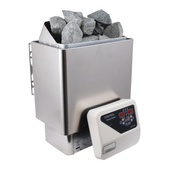
1. SPECIFICATIONS Commercial Domestic Dayliff Sauna heaters work by using electric elements to heat sauna stones. Two models are offered:- Domestic - Suitable for small sized saunas, especially domestic applications up to a room volume of 13m and comes with a separate intelligent digital controller that provides various control and monitoring functions including temperature settings and a timer. -
Page 4: Warnings
2. SYMBOLS AND WARNINGS This appliance must be connected to an MCB protected all pole isolator and installation done by a qualied person in accordance to local regulations. WARNING Disconnect the power supply before exposing electrical connections. WARNING The sauna heater should not be used for any other purpose WARNING Do not cover the sauna heater or allow contact with ammable materials such as towers due to risk of re. -
Page 5: Product Description
The wire which enters the sauna room must be type 60245 IEC 66 HO7RN-F (BSEN6141) WARNING Do not install two or more sauna heaters in one sauna room WARNING The sauna heater becomes very hot when in operation and must be guarded to protect incase of accidental contact WARNING 3. - Page 6 OC-SB Controller Fig 1 Dimensions Input Output Load Control Box 400V 400V OCS-B 9-20kW OC-SB Voltage: DC 5V Controller Description Function On/Off Button Push to operate heater Light Button Push to operate sauna room light Fan Button Push to operate fan Setting Button Preset time and temperature setting confirmation Increase Button...
- Page 7 Description Function When this LED is on the door has been opened as count Sauna Room down timer is set and so the timer is cancelled and the heater Door(interlock) won’t come on until the settings are reset indicator LED When this LED is on the safety overheat cut out thermostat High has tripped, this means the sauna has reached very high...
- Page 8 Function Instruction Description Wire Route of wire entry anchorage Connects to the power supply Terminal-1 Terminal-2 Connects to heater Heater ,light and fan Outlet of wires to heater ,light and fan output Control cable The entry of control cable entry Light terminal Connect to light wire Fan terminal...
- Page 9 Circuit Diagram Domestic Commercial Fig 4 Control Box Circuit Diagram for (9kW) Domestic Unit Fig 5...
- Page 10 Control Box Circuit Diagram for 12/15kW Commercial Unit Fig 6...
-
Page 11: Installation
4. INSTALLATION 4.1 Important Prior to installing sauna heater, please refer to installation handbook and check it as following points: • Is the output power and type of the heater suitable for the Sauna Room? See parameter table 1 (Technical Parameter) on page 1. •... -
Page 12: Installation For Controller
POWER OC-SB Controller Sauna Heater AC 400V 3N~ (Voltage=DC 5V) OCS-B Control Box Sensor Commercial Heater Fig 8 Control box output to sauna heater can not be bridged WARNING Master Slave 1 Slave 2 To next Controller slave Multi Sauna Heater Linking Function Fig 9 4.3 Installation for Controller The control panel should be installed at a height of approximately 1200mm for ease of use. -
Page 13: Installation For Temp Sensor
Fig 10 The control wire should plug into the silver / black DIN socket on the PCB of the main OCB control box. 4.4 Installation for Temp Sensor · Install the temperature sensor on the height between 1500-1800mm in sauna room. ·... -
Page 14: Heater Guard (Not Supplied)
4.6 Sauna Stones Ÿ Do not use the heater without sauna stones, otherwise it may cause a fire. These can be supplied from any Dayliff dealer. Ÿ Do not use ordinary stones which may emit harmful substances, easily break and do not possess good heating capacity. -
Page 15: Insulation
Ÿ Put the larger stones at the bottom of stove compartment and the smaller ones on top. Ÿ Do not pile them tightly so that air can flow freely. Tightly placed stones decrease working time of the heater element, the stones should plainly cover the heater element . NOTE Ÿ... -
Page 16: Operation
Ÿ The outlet vent should be placed diagonally opposite to the inlet. It is advisable that the outlet vent is placed under the platform in sauna room as far as possible from the inlet vent. Ÿ It can be installed near the floor, or from the floor through to a vent to the sauna ceiling, or under the door (to the wash room). -
Page 17: Setting Time & Temperature
Ÿ ” “ : Turns sauna light on/off Ÿ ” “: Turns sauna fan on/off Ÿ The Controller has a timing device used to set a time to power up the heater, this can be set from 0~12 hours as shown in the table 1 below. When the controller is in B Mode (Timer mode) the heater will not operate. -
Page 18: Door Interclock
Ÿ For quick time adjustment hold the “ “ or “ “ and it will count continuously up or down, when it reaches the desired time release the button and the time is set. Ÿ To adjust temperature : press “ “... -
Page 19: Maintenance
Description Cause Solution Door LED is During the advance Reset counter down timer t i m e r c o u n t d o w n sequence ,the sauna room door is opened, the timing stopped and will not restart again until it is reset. -
Page 20: Terms Of Warranty
8. TERMS OF WARRANTY I) General Liability • In lieu of any warranty, condition or liability implied by law, the liability of Davis & Shirtliff (hereafter called the Company) in respect of any defect or failure of equipment supplied is limited to making good by replacement or repair (at the Company's discretion) defects which under proper use appear therein and arise solely from faulty design, materials or workmanship within a specified period. - Page 21 INS496A-03/22...
Need help?
Do you have a question about the Domestic Series and is the answer not in the manual?
Questions and answers