Table of Contents
Advertisement
Quick Links
Advertisement
Table of Contents

Summary of Contents for SFC SFCR-MH
- Page 1 9/40 Layer Videowall Controller Operation manual SFCR-MH & SFCR-MD...
-
Page 2: Table Of Contents
Contents 1 Introduction ........................................1 Performance Characteristics Features................................. 1 2 Hardware Installation ....................................... 3 System requirement ....................................3 Installation environment ....................................3 Installation environment requirements ..............................3 Recommend operating environment ..............................3 Hardware installation steps .................................. 3 Network connection ....................................3 Connection instruction .................................... - Page 4 CAUTION • Non-technician should not try to operate this controller before reading this manual carefully. (This manual are subject to change without prior notice.) • Cut the power supply off before operating the device to avoid damage caused by mal-operation. •...
- Page 5 CKING LIST Check if the packing contents match the packing list on receiving the products. The packing list is as below. Part Quantity DTMH/DTMD-04-4H4H Mounting kit Quick Start Guide Contact your local supplier if anything is missing in your package.
-
Page 6: Introduction
1 Introduction erformance Characteristics Features Equipment architecture: 1. FPGA + embedded architecture, the embedded system is stable, can support 7 * 24 hours of long-term operation, FPGA provides users with stable image processing capabilities; 2. The equipment adopts a modular design, which can be flexibly matched with a variety of input and output boards, which can be upgraded, expanded, and maintained;... - Page 7 23. Support output port mapping technology. There is no need for one-to-one correspondence between the connection cables between the device and the display unit. It is only necessary to ensure a valid connection. Port mapping settings are completed in the control software, which greatly simplifies the installation process and shortens the installation time.
-
Page 8: Hardware Installation
2 Hardware Installation System requirement • Web browser: LAN Internet connect , via PC Ethernet ( network card or network cable) TCP/IP protocol • Monitor and PC configuration: CPU: PⅢ or latter, RAM: 2GB • Operation system: Windows 7 or later Installation environment Installation environment requirements Far away from humid or high-temperature environment;... -
Page 9: Connection Instruction
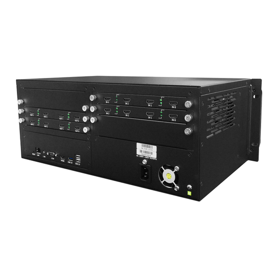
Connection instruction The appearance of the device is shown in the following figure; 1. The number "1" marked in the figure is the video output port of the processor, which is connected to the screen cable; the cable is freely inserted into the OUT port on the processor, we will set the order later in the software;... -
Page 10: Pc Software Installation
3 PC Software Installation Get the PC control software and IP setting tool There are 3 methods to control the LCD video wall controller, here I introduce the PC software control steps: double click the controller PC software ("WTRemote_V1.0.X.X_setup.exe") then the below picture will pop out, click “Next”: then the below picture will pop out, click “Next”. - Page 11 Then click to select create a desk icon, and then click”Next”: And click”Install” to install the software on your computer: Please wait the install the install processing: After the installation completed, you can click “launch WTRemote” to operate the software, and then click “Finish”.
- Page 12 And the PC software icon and the IP setting tool(SearchNvsDemo.exe) will on the computer automatically, the icons as following picture shows : At the same time, you will get the PC software login interface,as following picture shows :...
-
Page 13: Pc Control Software Operation
PC control software operation You will get the IP address on the PC software login interface automatically after you connect successfully, the original user name of the processor is: admin, the password is empty; if a different user and password are set, you need to log in according to the actual user name and password, Follow the steps indicated by the numbers in the below picture: After login, you will get a interface as below: ... - Page 14 1. Screen resolution: set the resolution of the video output port; 2. Physical screen: set the number of rows and columns of the screen; 3. Logical screen: how many windows are divided by a single screen; 4. Port settings: pop-up screen port settings. ...
-
Page 15: Pc Software Main Interface Introduction
PC software main interface introduction On the main interface the top horizontal bar, there are “Main function”, “Background manage", “Subtitle manage”, “Maintenance” and “System” totally 5 parts. On the interface left part, it have “Video input source”, “Group management”, “Net video source” three parts. After run the processor operating software and login, the signal source will list on the middle left under the “Video input source”... -
Page 16: Matrix Mode
When there are multiple sets of independent screens to be controlled by one controller, it is necessary to separate these groups of screens in the control software.( If there is only one set of screens in the field, no screen grouping is required). Specific steps are as follows: 1)Select the No.1“screen group 2”(If have screen group 3,screen group 4, you can select corresponding) 2)Click No.2 “Enable screen group”... -
Page 17: Video Input Source
Click "Matrix mode" in the main function tab to make its background blue. You can adjust the processor to matrix mode. In matrix mode, all windows cannot be dragged to prevent misoperation; click again "Matrix mode" button to cancel the matrix mode. At this time, the signal source window can be dragged. - Page 18 When a valid signal is connected to the processor, the system can automatically detect the input signal. Expand the tree structure ,When the to see each input port. When the processor input port does not detect a signal input, the port indicator in the software is gray (DVI、VGA、BNC、SDI processor input port detects a valid signal input, the corresponding port indicator in the software turns green signal detection method is consistent), pls refer to below picture:...
-
Page 19: Main Function-Window Control
After setting, you can see the icon of combined input in the video input list, double click the icon to open sources. 3.1.4 Main function-Window control 3.1.4.1 Open new source A newly opened window refers to the input signal being displayed on the mosaic wall in the form of a window. In the control software of the processor, there are various ways to open the window. - Page 20 Source on the screen 3.1.4.4 Single screen split Single-screen split-window refers to opening multiple different signal source windows in one screen. There are two methods for single-screen split-window: Method 1:in the part of “Window control”, select the number of rows and columns that need to be split for a single screen, split the single screen into multiple logical screens, and then select the logical screen to open the sources.
- Page 21 Select the template you want to apply, such as one screen, four screen, nine screen, sixteen screen, sixty screen. Click the select template to pop up the “Select Video Source” dialog box as shown below, select the source to be displayed and import it to the right of the dialog box, and then click OK to complete the single screen split window operation.
-
Page 22: Moving Source
3.1.4.5 Full screen split Full screen segmentation refers to using the entire splicing wall as a logical screen and splitting and opening the window. Specific steps are as follows: Enter the main function tab, select the row and column number, and then click quickly window After selecting a template, in the pop-up "Select Video Source"... -
Page 23: Modify The Layer Sequence
Enlarge a window to full screen: left-click on the main view to select the target window, and then move the mouse arrow to the upper right corner of the window, click full screen button, then this source will get full screen. 3.1.7 Modify the layer sequence Method 1: When multiple sources are stacked, click one of them with the left mouse button to directly put this source on top Method 2:When multiple sources are stacked, right-click on a source and select the corresponding operation to complete the... - Page 24 Click “clear” to clear all sources on the screen...
-
Page 25: Image Attribute
3.1.9 Image attribute The image properties include the basic information of the input video source, image cropping, and video adjustment. The basic information includes the name, type, interface location, and video format of the signal source. View and adjust the image properties as follows: In the video input source, select the video signal whose image properties need to be adjusted, right-click, and select "Image Properties". - Page 26 Source name display: Source name will display on the left up corner, click to switch the name display or not( For this function , you have to focus on the screen to test, the software source name won’t disappear) Click to adjust the source name font size, color, and typeface.
- Page 27 The picture cut function is suitable for DVI, VGA, SDI, and BNC signals. The image cropping function can cut the left, right, top, and bottom parts of the source image separately, which is suitable for taking out the black edges of the signal source or partially enlarging the signal source.
-
Page 28: Group Management
3.1.10 Group management The Group management function is to save the plan which is convenient for the next call. 3.1.10.1 Save group After the layout of the video source is completed, in the "Main function" tab, click the "Save modal" button, and enter the name of the plan in the "Save modal"... - Page 29 7、 successfully, the added plan name will be displayed in the list on the right side of the dialog box. Use the left mouse button to select a scene name and click the button to delete the added plan in the plan group. Click to adjust the order of playback.
-
Page 30: Net Video Source
3.1.10.4 Group switch There are two ways to switch plans, one is manual switching, and the other is automatic polling. 3.1.10.4.1 Manual switch You can see the preview pictures of all the saved plans in the "Plan Management" at the bottom left of the processor's control software interface. - Page 31 3.1.11.2 Preview display setting To make the encoder work, you first need to set an independent IP address for each IP encoder. The encoder IP address setting method is as follows: Click "Maintenance"-"Encoder" to pop up the encoder setting dialog box ...
- Page 32 3.1.11.3 IP camera input IP camera access is not limited to cameras, but can also access RTSP streams in H.264 encoding format of DVR, NVR, streaming media server, encoder and other devices. 3.1.11.3.1 Add group When there are many front-end IP cameras, the cameras need to be grouped. In this case, you need to manually add groups. The specific steps are as follows: 1.
- Page 33 If you need to move the auto-discovered cameras to different groups, you can use the left mouse button to select the target camera icon, and then right-click to select "Move to group" and click the corresponding group; The name of the auto-discovered camera is the same as the IP address of the camera. If you want to modify the camera name, you can right-click the camera and select "Edit".
-
Page 34: Background Manage
Manual add If the front-end camera cannot be found automatically or you want to access the RTSP code stream forwarded by the NVR, DVR, or streaming server, you need to manually add the camera or RTSP code stream (the camera must be based on the standard Onvif protocol). The steps are as follows: Click the Add Camera button to enter the "Add IP Camera"... -
Page 35: Subtitle Manage
Click the full screen button in the upper right corner of the new picture, the picture is full Click End Edit to send the picture and exit the background management. If the position of each display unit picture is disordered after the background editing is completed, please check whether the screen settings in the software are correct or whether the display unit is set to stitching mode. -
Page 36: Import Existing Subtitle Files
Click OK to complete the modification If you don't need to modify the text content of the subtitles, you can modify the font, font size, font color, background color, background transparency, scroll method of the subtitles in the shortcut keys in the properties options, and modify the scrolling speed of the subtitles in the scroll speed (The larger the value, the faster the scroll speed) ... -
Page 37: Adjust The Scroll Direction Of The Subtitles
3.3.6 Adjust the scroll direction of the subtitles In the subtitle editing mode, click in the "Attribute" area, and the subtitles scroll from right to left. In the subtitle editing mode, click in the "Attribute" area to scroll the subtitles from the bottom to up. 3.3.7 Adjust the scroll speed of the subtitles In the subtitle editing mode, click the corresponding speed in the "Roll Speed"... - Page 38 Step1:Click enable screen group, and set the physical screens and logical screens(For example we have total screens, and use 3 screens as main group screens, and use one screen as back display screen), input the number as upper picture,then click upper right “Port- set”, select “main screen”, and drag the left main screen group as the screen display port to the right part;...
- Page 39 Here's how to set up an independent monitor: A. Connect the independent monitor to the controller output port and adjust the display to single-screen mode. B. Click "Maintenance-screen set" in the control software to pop up the "Screen Set" dialog box. C.
- Page 40 Parity check: Noparity Databits:8 Stop bit:1 3.4.1.3.1 Pocket format The Center management platform send commands to the DTMH/DTMD controller or the DTMH/DTMD controller send responses to the Center management platform, the data will all collect to data pocket, all the data pocket format will start as “$” and end with “^” char. Op means operate commands, one char.
- Page 41 * Switch the video source Central command: One byte, ranging from 1 to 4, specifying the sequence number of the screen packet DATA [Screen type][Number][video source number] Explain For the DATA, the [ ] cannot omit Screen type:0 means main screen, 2 means left independent screen, 3 means right independent screen Number: It’s show on the picture below video source number: According to the Frame number(f), Card number(c),Child card...
-
Page 42: Maintenance-Signal Name
Replace the video source 359 to Number 1 on the right independent screen $51[3][1][359]^ Replace the video source 259 to Number 2 on the main screen $52[0][2][259]^ Device response DATA Ok or Error 3.4.2 Maintenance-Signal name Uses click “Show switch” to select display or don’t display the source name on the screen, and users can set the source name format, colors,etc. -
Page 43: Maintenance-Screen Switch
3.4.3 Maintenance-Screen switch Input the screens power on/off commands, then click “Open” and “Close”button to controller the screens power on/off remotely 3.4.4 Maintenance-Advanced setting The “Advanced setting” is used to check the video wall controller working states, and by click “Modify EDID” can set the screens drive board resolution. -
Page 44: System-User
3.5.3 System-user Set the user name and user permissions according to the user’s need, also can change the PC software language. -
Page 45: Tablet App
4 Tablet App App installation and login App login Support Android system tablet and mobile APP installation control, but do not support Apple system. Install MnltiVideoController software on mobile phone and Android system tablet,the network segment of tablet and mobile phone must be on the same network segment with the processor, otherwise the software cannot login After logging in, enter the IP, account, and password of the processor. - Page 46 Note: Only FDMD support the source preview and screen sync display in the software, and need additional input card.
-
Page 47: Ip Address Setting
5 IP address setting IP setting tool Tool operation User come back the PC desk to find the IP setting tool icon , double click to operate it, then the below window will pop-up, click “Search device”: Then the connected process IP address will display, selected you wanted modify one, click “Parameter setting”: Input the new address, after input the net mask and gateway, click “Change”... -
Page 48: Appendix
6 Appendix Frequently asked questions Failure phenomenon Troubleshooting Note The source layer creation fails in a simple scenario, Click the refresh button or click the souce and nothing is displayed on the screen Check if the power switch on the rear panel is turned on or the Power light is off power cord is plugged in firmly Check if the corresponding video connection of the device is...
Need help?
Do you have a question about the SFCR-MH and is the answer not in the manual?
Questions and answers