
Summary of Contents for CLIMET INSTRUMENTS CI-154
- Page 1 CI-154 LASER PARTICLE COUNTER OPERATOR’S MANUAL Revision 3.20 – December 28, 2015 CLIMET INSTRUMENTS 1320 West Colton Avenue, Redlands, CA 92374 Manual P/N 03015400 PHONE: (909) 793-2788 FAX: (909) 793-1738 www.climet.com...
- Page 2 CI-154 User’s Manual Page ii...
- Page 3 BACKDOOR SUPERVISOR PASSWORD Climet Instruments Co. and authorized Climet service providers are able to disclose a secret supervisor password to enable a supervisor to gain access to their counter if the password set by the supervisor has been forgotten. Starting with version 3.00, a program was developed that enables a temporary password to be...
- Page 4 CI-154 User’s Manual Page iv...
-
Page 5: Table Of Contents
2.1.1 The CI-154 chassis ______________________________________ 9 2.1.2 The CI-154 user interface _______________________________ 10 Performing routine tasks with the CI-154 _______________ 11 2.2.1 How to take a sample ___________________________________ 11 2.2.2 How to set an alarm level for particle count _________________ 11 2.2.3... - Page 6 CI-154 User’s Manual 2.2.14 How to clear stored data ________________________________ 19 Changing paper ____________________________________ 19 Battery operation __________________________________ 20 Sample settings ___________________________________ 20 2.5.1 Sample volume ________________________________________ 20 2.5.2 Initial delay___________________________________________ 20 2.5.3 Sample delay _________________________________________ 21 2.5.4 Number of samples ____________________________________ 21 2.5.5...
- Page 7 USB interface _____________________________________ 41 3.1.1 3.1.1 CSV file format ___________________________________ 41 RS-232 interface ___________________________________ 43 3.2.1 Controlling the CI-154 through the RS-232 interface __________ 43 Ethernet interface __________________________________ 44 3.3.1 Connection and Factory Settings __________________________ 44 3.3.2 The Configuration Utility. ________________________________ 44 3.3.3...
- Page 8 CI-154 User’s Manual Monitoring _______________________________________ 72 5.2.1 The where, why, and how of monitoring ____________________ 72 5.2.2 5.2.2 Monitoring hot air sources __________________________ 73 Service and maintenance ____________________________ 75 User maintenance __________________________________ 75 6.1.1 Battery replacement ____________________________________ 75 6.1.2 Fuse replacement ______________________________________ 75 6.1.3...
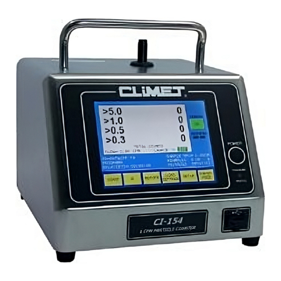
- Page 9 CI-154 User’s Manual FRONT VIEW OF CI-154 Page ix...
- Page 10 CI-154 User’s Manual REAR PANEL OF CI-154 Page x...
-
Page 11: Introduction
1.2.3 Patents The CI-154 is protected by one or more of the following U. S. or Japanese patents: US RE 37,353E 5,515,164 5,825,487 ... -
Page 12: Unpacking And Installation
The CI-154 contains a 9.6 Volt, maintenance-free, rechargeable nickel metal hydride battery, which can be replaced by the user. The CI-154 comes with a three prong, grounded AC power cord. Failure to make a proper earth ground connection may result in a shock hazard and may damage the instrument. -
Page 13: Storage
The CI-154 has a sample flow rate of 1 cubic foot per minute (1 CFM) or 28.3 liters per minute (28.3 LPM), requiring 35.3 minutes to take a full 1 cubic meter sample. - Page 14 Other sample settings program the CI-154 to take a certain number of samples, then stop, or to take samples once every given time period. Averages can be automatically printed at the end of a given number of samples.
- Page 15 CI-154 User’s Manual The CI-154 has been designed to provide rugged, long-term performance. The laser diode light source is controlled with a closed loop drive circuit to maintain a constant intensity over time and temperature variations. The status of the laser power is monitored and displayed as on the main screen.
- Page 16 CI-154 User’s Manual Page 6...
-
Page 17: Specifications
CI-154 User’s Manual Specifications Illumination source: Laser diode, 50 mW Light Collection Optics: Elliptical mirror Detection: Silicon photo diode 0.30 m Size sensitivity: Particle channel sizes: Four sizes: 0.3, 0.5, 1.0, 5.0 m Size resolution: Meets requirements of ISO 21501-4 - 10% typical Concentration limit: 1.0 x 10... - Page 18 CI-154 User’s Manual Page 8...
-
Page 19: Operation
2.1.1 The CI-154 chassis The CI-154 has a brushed, stainless steel chassis to maintain a clean appearance while providing the preferred covering for equipment that may be routinely exposed to harsh, disinfectant solutions. An overlay covers the LCD touch screen and power switch, protecting them during cleaning. -
Page 20: The Ci-154 User Interface
2.1.2 The CI-154 user interface The CI-154 uses a color touch screen display that allows the user to control the operation of the CI-154 through soft keys on the display’s touch screen. The unit is turned on by a momentary switch to the right of the display. There will be a slight pause—about four seconds—... -
Page 21: Performing Routine Tasks With The Ci-154
CI-154 User’s Manual Performing routine tasks with the CI-154 2.2.1 How to take a sample Before taking a sample, first make sure that the dust cap has been removed from the inlet. If a sample probe is used, it should be pointed towards the HEPA filter when sampling a laminar flow area. -
Page 22: How To Set An Alarm Level For Flow
2.2.4 How to create and use a stored program The CI-154 allows you to configure parameters and location IDs for a given sample area and save them under a named program, so that the parameters can be easily recalled every time you have to sample that area, or areas, with similar requirements. -
Page 23: Using Stored Programs On A Usb Jump Drive
CI-154 User’s Manual CAUTION: Stored data in reports is grouped by programs. Altering sample parameters without saving changes to a program assigns the data to a blank program. Read below for further details. To load saved settings, press [ ] at the bottom of the main data screen. -
Page 24: Using The Clone Feature Via Usb
CI-154 User’s Manual Selecting [ ] will bring up a menu with a list of the programs available LOAD SETTINGS on the drive. The user may navigate through the list and use the [ SHOW SETTINGS button to view the settings of the program. Settings may also be printed from this screen. -
Page 25: How To Create And Use Location Ids
CI-154 User’s Manual 2.2.7 How to create and use location IDs The location IDs are used to identify the location where the sample was taken. The location ID is printed on end of sample printouts and with data sent to a computer. - Page 26 CI-154 User’s Manual ] is enabled Press [ Message appears AUTO ADVANCE START NEXT ID and sampling is “END OF ID LIST” [ completed for the last ID in the list. Page 16...
-
Page 27: Using The Clone Feature Via Rs-232
2.2.10 How to print data Printing sample data The data collected by the CI-154 can be printed automatically at the end of each sample, or the data can be printed as a data dump from memory. The printer can print with large or small fonts. Font size selection is under the [ ] menu. -
Page 28: How To View Stored Data On-Screen
Printing alarm violation reports The CI-154 can print out a report of all alarm violations for the data still in memory. To print the report, press [ ] from the main data screen, then press [... -
Page 29: How To Copy Stored Data To The Usb Jump Drive
Data should also be cleared if data dumps are routinely taken, so that old data will not be repeatedly printed or sent to the computer. Since the CI-154 can store a considerable amount of data, failing to clear data regularly will result in very long printouts, both in terms of time and in terms of paper length. -
Page 30: Battery Operation
2.5.1 Sample volume The CI-154 has a constant flow rate of 28.3 liters per minute, or 1 cubic foot per minute. At this rate, the particle counter samples a cubic meter of air in 35.3 minutes, a cubic foot of air in 60 seconds. -
Page 31: Sample Delay
For example, if you wanted to take a 1–minute sample automatically every hour, then you would set the sample delay to 60 minutes. Then the CI-154 will treat the sample delay as a recurring interval in which it will perform an initial delay of 5... -
Page 32: Auto-Average
CI-154 User’s Manual To set the CI-154 to take a fixed number of samples (for example, 4) press the ] key from the sample group, which will turn from green to yellow. The STOP AFTER N number of samples is then established by pressing the [ ‘... -
Page 33: Printer Settings
To set the CI-154 up for concentration counts in cubic feet, press [ ], then [ ] in the display group. To set the CI-154 to display concentration in cubic meters or liters, press [ ] or [... -
Page 34: Printing Alarms Only
CI-154 User’s Manual Example End of sample printouts (2 channels) TWO END OF SAMPLE PRINTOUTS TWO END OF SAMPLE PRINTOUTS USING LARGE FONT USING SMALL FONT (2 CHANNELS) (2 CHANNELS) 11/16/09 15:30:00 PROGRAM= IN OPERATION ID= LOCATION 24A 11/16/09 PROGRAM= IN OPERATION SAMPLE VOL= 1.0CF SAMPLE#= 1 TOTAL COUNT... -
Page 35: Setting Alarms
EXIT return to the main screen. The CI-154 can be set to beep whenever a particle is detected. This is useful, because you can use the instrument—much like a Geiger counter—to home in on contamination sources in a clean area. As you approach the source of contamination, the beeps occur at a faster rate, and as you move away from the source, the beeps become less frequent. -
Page 36: Alarm Indicators On The Display
(green) and you wish to disable it, press the same key so that it turns yellow. When the CI-154 is set to Beep on Count or Audible Alarm, the high output beeper on the underside of the chassis will sound. This beeper has an adjustable baffle which the user can turn to give the desired audible output level. -
Page 37: Creating An Id
Different clean rooms and clean hoods may require different settings for sampling. The CI-154 allows those settings to be named and saved as programs so that the user can quickly change settings from one area requirement to the next without having to recall the details of how each area is to be sampled. -
Page 38: Getting Reports
CI-154 User’s Manual program. To delete a program, highlight the program that you want to delete, using the [ ] and [ ] keys, then press [ UP SELECT DOWN SELECT DELETE If you enter the [ ] menu, but decide not to save a new program, make... -
Page 39: Selecting Data To Report
CI-154 User’s Manual of the settings, to be kept with the data collected using a given program. The printouts can also be used to see all settings at once, without having to go from screen to screen on the display. -
Page 40: Printing All Stored Data
CI-154 User’s Manual 2.13.4 Printing all stored data To perform a data dump (print all stored data), press [ ] from the report ALL DATA menu, then press [ ] from the menu of keys at the bottom of the screen. Two PRINT examples follow. -
Page 41: Printing Alarm Data
CI-154 User’s Manual Example stored data reports: 2 channels STORED DATA PRINTOUTS USING STORED DATA PRINTOUTS USING LARGE FONT SMALL FONT (2 CHANNELS) (2 CHANNELS) STORED DATA STORED DATA #LOCATIONS= 1 #LOCATIONS = 1 #SAMPLES = 4 PROGRAM= CLASS B ZONE 1... -
Page 42: Printing Average Data
CI-154 User’s Manual 2.13.6 Printing average data A printout of the averages of data stored for each location can be made from the report menu. Access the report menu by pressing the [ ] key from the main REPORT data screen. From the next screen, press [ ]. -
Page 43: Printing An Iso 14644-1 (2015) Report
CI-154 User’s Manual Example Report: 2 channels, 0.5 and 5.0 m, security enabled AVERAGE REPORT USING AVERAGE REPORT USING LARGE FONT SECURITY ENABLED SMALL FONT SECURITY ENABLED (2 CHANNELS) (2 CHANNELS) AVERAGE DATA AVERAGE DATA UNIT= BLUE ZONE UNIT= BLUE ZONE... -
Page 44: Printing An Fs-209E Report
CI-154 User’s Manual Example Report: 1 channel, 0.5 m ISO 14644-1 REPORT ISO 14644-1 REPORT USING LARGE FONT USING SMALL FONT ISO 14644-1 REPORT ISO 14644-1 REPORT PASS PASS UNIT= CLIMET #1 UNIT= CLIMET #1 ISO CLASS 9 (AT 0.5 uM) ISO CLASS 5 (AT 0.5 uM) - Page 45 CI-154 User’s Manual Example Report:FS-209E, 1 channel, 0.5 m FS-209E REPORT FS-209E REPORT USING LARGE FONT USING SMALL FONT FS-209E REPORT FS-209E REPORT PASS PASS UNIT= CLIMET #1 UNIT= CLIMET #1 CLASS 100000 (AT 0.5 uM) CLASS 100000 (AT 0.5 uM)
-
Page 46: Printing A Gmp 2008 Report
CI-154 User’s Manual 2.13.9 Printing a GMP 2008 report The GMP 2008 report screen is accessed from the report menu screen. Next select [GMP 2008] to enable GMP 2008 reports. Press [ ]; from the screen that SET CLASS follows, press the desired GMP 2008 grade for the area being monitored. The selected key will turn green when pressed. - Page 47 CI-154 User’s Manual Example Report: GMP 2008 GMP 2008 REPORT GMP 2008 REPORT USING LARGE FONT USING SMALL FONT GMP 2008 REPORT GMP 2008 REPORT FAIL FAIL FAILS UCL UNIT= CLIMET #1 USER= SUPERVISOR UNIT= CLIMET #1 GRADE C in OPER. (AT 5.0 uM)
-
Page 48: Security
CI-154 User’s Manual 2.14 Security 2.14.1 Enabling security Security is enabled from the main screen by pressing [ ], [ ], [ ] to MORE MORE display the security screen, then pressing [ ] (green), followed by [ ]. The... -
Page 49: Add/Remove Users
This is literally a red flag to warn that a password needs to be entered by the user to prevent unauthorized access to the CI-154. Users with passwords have their names in black print, just like the log in screen. -
Page 50: Lock Unit
2.14.5 Unit ID The CI-154 can be assigned a 1 to 16 character identification which will appear on all printouts and the top of the ID listing screen. To set the unit ID, press [... -
Page 51: Auxiliary Connections
CI-154 User’s Manual Auxiliary connections USB interface The USB interface is designed for use with USB jump drives. As such, stored data can be copied from the internal memory of the unit to the USB drive. The data is saved as an ASCII file in CSV (comma separated values) format. A check code is calculated and appended at the end of the file. - Page 52 CI-154 User’s Manual Alarm,Date,Time,Location,UnitID,UserID,Program Name,Run #,Volume,Count Mode,0.3 Micron,0.5 Micron,1.0 Micron,5.0 Micron,Flow CFM,Unit S/N,Laser OK,Flow OK,Cal Due 0,8/17/2007,3:18:18,SET 1,TEST UNIT,INSPECTOR 1,SYSTEM REVIEW ,1, 0.01CM,TOTAL COUNTS,103559,12690,842,169,1.00,123456,1,1,6/17/08 0,8/17/2007,3:18:24,SET 1,TEST UNIT,INSPECTOR 1,SYSTEM REVIEW ,2, 0.01CM,TOTAL COUNTS,103717,12530,956,140,1.00,123456,1,1,6/17/08,3B26A7E3 ASCII CSV Text File Format on USB Jump Drive...
-
Page 53: Rs-232 Interface
Controlling the CI-154 through the RS-232 interface The CI-154 can be programmed and operated by means of the RS-232 port. The CI-154 responds to external commands that are sent in ASCII alphanumeric characters. The table in section 3.3 lists the ASCII characters and their functions. -
Page 54: Ethernet Interface
(IP address) set. Obtain an IP address from your network administrator. Connect the CI-154 to any non-network computer using an Ethernet crossover cable, which plugs directly into the Ethernet ports of the CI-154 and computer. Turn the CI-154 on. Wait one minute. Get to the main screen, then press [ ] and ] to view the current network address settings. - Page 55 CI-154 User’s Manual After opening the configuration utility, click the search button to locate the unit to be configured. The list of units on the network will show on the left. Make a selection of which unit to configure by clicking its MAC or IP address. An S or D next to the address indicates if the unit has a static address or one assigned by DHCP.
-
Page 56: Connecting Using Telnet
CI-154 User’s Manual After the unit has restarted, check the CI-154 settings screen by pressing the ] buttons. The following is an example screen. The unit requires 45 SETUP NETWORK seconds after power up before the network information is displayed on this screen. - Page 57 CI-154 User’s Manual When the login prompt comes up, type in the user name and press return, type in the password and press return. Once connected the following screen should appear. Connect by selecting option 1, 2 or 3. Option 1 will configure# the counter to send End Of Sample data to the Telnet client window.
-
Page 58: The Rs-232 And Telnet Command List
CI-154 User’s Manual 3.3.4 The RS-232 and telnet command list The following is a list of the commands that may be received through the RS-232 port or the Ethernet port via the telnet protocol. Unless otherwise indicated, all commands must be terminated with a <CR>. A <BEL>... - Page 59 CI-154 User’s Manual ASCII Note FUNCTION Force cumulative count mode—as opposed to concentration mode. Force concentration mode: counts/cubic foot. Force concentration mode: counts/cubic meter. Force concentration mode: counts/liter. Enable touch screen keyboard. Disable touch screen keyboard. Send current date, time, location ID, unit ID, user ID, program name, run #, volume, count mode, counts, flow, unit S/N, laser status, flow status and cal due date.
- Page 60 CI-154 User’s Manual ASCII Note FUNCTION Returns three arguments: count mode total or differential, concentration per unit and current sampling state Arg1 1 character: L = Total, l = Diff Arg1 2 character: c = Counts, H = Per CM, C = Per CF, h =...
- Page 61 CI-154 User’s Manual ASCII Note FUNCTION x=1 to enable or 0 to disable confirmation screen with ACK1=x (s1) message: “CONFIGURATION OF COUNTER WILL BE CHANGED” [CONFIRM] [CANCEL] If enabled, BAT command execution will require user confirmation. ACK1 argument must be the first command in the BAT series of commands.
- Page 62 CI-154 User’s Manual ASCII Note FUNCTION Load named program and ID (optional). Execute command Jprogram,ID, (optional) Examples: JPROGRAM 1 (Loads program named PROGRAM 1.) JPROGRAM 1,LOCATION A,S (Loads PROGRAM 1, sets ID to LOCATION A, starts counting.) Set stored data file name on USB drive. One to eight jabcdefg.xyz...
- Page 63 CI-154 User’s Manual ASCII Note FUNCTION Disable end of sample transmissions. Enable end of sample transmissions. (Default on power up.) Send last end of sample data. String will include the last count mode and extra information if enabled. Enable extra information in end of sample transmissions or response to “F”...
-
Page 64: Rs-232 And Telnet Output Format
CI-154 User’s Manual Sending a request for a number of samples that is greater than the number of records in memory (e.g., #5,1 with only 5 samples in memory) with result in the following error message: EMPTY RECORD 3.3.5 RS-232 and telnet output format Listed below are the lines that are printed on the fly in response to character commands. - Page 65 CI-154 User’s Manual Response to the “Y1” command: CI-154 SN000000 Software Revision 1.00 Last Calibration: 06/03/08 Next Calibration: 06/03/09 ID=TEST ID SAMPLE VOL= 0.2CF NUMBER OF SAMPLES= 2 INITIAL DELAY=00:00:05 SAMPLE DELAY =00:00:00 4 SAMPLES STORED UNIT= USER= PROGRAM= PROGRAM1...
-
Page 66: Modbus
CI-154 User’s Manual 3.3.6 MODBUS®: Modbus® is a trademark assigned to Modbus-IDA. Modbus over TCP/IP provides control and configurability over a network connection. Modbus communication is an industry standard and allow users to connect the particle counters for setup and operation on a network. - Page 67 CI-154 User’s Manual The following list provides coil write examples for all coils in the unit. Note that Modbus coil numbers are offset from the address by 1. MBAP HEADER + Coil #, Command DATA FUNCTION CODE 101, Set Active...
- Page 68 CI-154 User’s Manual The following Holding Registers provide access to data stored within the unit’s memory. Holding Registers (Read) Data Contents 40001 (upper), 40002 (lower) Sample number 40003 (upper), 40004 (lower) Status(see Status for details) 40005 (upper), 40006 (lower) Sample Volume (x100)
- Page 69 CI-154 User’s Manual The following Holding Registers are in some cases redundant to the registers above but are arranged so that more information can be acquired more efficiently with a single block read. Holding Registers (Read) Data Contents 40201 – 40206 Date/time.
- Page 70 CI-154 User’s Manual The following Holding Registers provide a means to set the date and time of the counter by writing to the Modbus registers. Holding Registers (Write) Data Contents 41001 – 40006 Set date/time. Must write to all six registers:...
- Page 71 CI-154 User’s Manual To read the location ID registers of the most recent sample, issue the command as follows: MBAP HEADER FUNCTION CODE DATA Sent to unit 00 01 00 00 00 06 01 00 64 00 08 Received from unit...
-
Page 72: Status Bits Defined
3.3.8 Unit web server pages: The CI-154’s built in web server provides view only information from the CI-154. This information is provided on four web pages, listed below. The first page provides last sample information. The second page provides details about the CI-154. The last two pages provide a list of samples, sampledatap1.htm provides up to 60 of the... - Page 73 CI-154 User’s Manual Most Recent completed sample, Web address: http://UnitIPAddress/ (CI-1054 shown. Typical for other models.) Page 63...
- Page 74 CI-154 User’s Manual Unit Information, Web address: http://UnitIPAddress/info.htm (CI-754 shown. Typical for other models.) Page 64...
- Page 75 CI-154 User’s Manual Sample data up to 60 samples, Web address: http://UnitIPAddress/sampledatap1.htm Sample data up to 3000 samples, Web address: http://UnitIPAddress/sampledatap2.htm (Examples for CI-1054 shown. Typical for other models.) Page 65...
-
Page 76: Alarm Connector
CI-154 User’s Manual Alarm connector A 6-pin male connector is located in the lower right corner of the rear panel. This alarm connector is connected internally to a relay such that pins 3 and 4 of the connector have continuity at all times except when the unit has an alarm condition. -
Page 77: Theory Of Operation
CI-154 User’s Manual Theory of operation How particles are detected As you enter an old barn, you see a shaft of bright light shining down from the space between two of the boards that are part of the barn’s wall. A myriad of specks of light dance about within that shaft of light. -
Page 78: The Airflow System
4.2.2 The light source The CI-154 uses a laser diode light source. The superior light collecting properties of Climet’s optical system allows the laser diode to be driven at a much lower level which adds to the life of the laser diode. Lenses are used to shape the laser beam. A light trap at the opposite end of the sensor absorbs the beam, so that it will not create stray light that would obscure smaller particles. -
Page 79: The Electronic Subsystems
Amplifier and signal processing circuits amplify the signal, and attenuate background noise, which allows smaller particles to be detected. The CI-154 uses patented (5,870,190) Digital Signal Processor (DSP) circuitry to electronically sort these pulses and set threshold voltages. - Page 80 CI-154 User’s Manual Page 70...
-
Page 81: Application Guide
The Isokinetic probe is the cone-shaped sample probe that is provided as a standard accessory for the CI-154. Often referred to simply as the isoprobe, it is used when sampling laminar airflow, such as the airflow from a HEPA filter. When used to sample laminar flow, the probe should be pointed towards the source of the flow. -
Page 82: Monitoring
CI-154 User’s Manual The particle counter requires a minimum flow through the diffuser and if the valve drops the airflow below this requirement, the particle counter may suck in ambient air, contaminating the gas sample. The diffuser will reduce the pressure to atmospheric level, and an adequate flow will enable the particle counter to sample the gas sample without outside contamination. -
Page 83: Monitoring Hot Air Sources
CI-154 User’s Manual monitoring is about risk assessment, and only general guidelines can be given for monitoring. Fundamental to this is to understand why you are monitoring for particle counts. To assess the risks you have to identify which products or processes are critical and select those for more frequent monitoring. - Page 84 CI-154 User’s Manual Page 74...
-
Page 85: Service And Maintenance
6.1.1 Battery replacement There are two batteries in the CI-154. One is the memory back-up battery. It backs up memory while the unit is off. The memory back-up battery can last up to eight years. Actual times will vary because of the variation in the percentage of time that the unit is off during the day. -
Page 86: Long Term Storage
(P/N 01249500 for the CI-154 and other 1 CFM models). This patented device blocks light without trapping 5 m particles. Other designs that have been implemented to block light have a serious problem with 5 m loss. -
Page 87: Low Laser Power
Low laser power The CI-154 constantly checks the status of the laser diode. If the unit detects a loss of laser power, a screen reporting “Low Laser Power” will appear and sampling will stop. Pressing [ ] will clear this screen. - Page 88 CI-154 User’s Manual Our Eastern Service Center can be reached by phone at 434-984-5634, by fax at 434-293-3938, or by email at service@climet.com. When shipping units, use the original shipping carton, a well padded shipping case, or in a box that allows at least three inches of bubble wrap extending from the greatest protrusion on all sides of the instrument.
-
Page 89: Frequently Asked Questions
All count data is stored as raw count data. It is then displayed, printed, or transmitted according to the current settings by making the necessary conversions on the fly while sending the data to its destination. Does the CI-154 comply with 21 CFR 11? REPORTS Page 79... - Page 90 STORED DATA FILES ON USB JUMP DRIVE The CI-154 provides a means to detect if a stored data file on the USB drive has been altered by appending a 32 bit check code to the end of the file. By...
- Page 91 Alarms are detected by comparing the actual total counts to the alarm value. If the sample volume is set to 1 cubic foot (one minute on a CI-154), that is about 1/35 of a cubic meter.
- Page 92 CI-154 User’s Manual Page 82...
-
Page 93: Appendix
Appendix Legacy Modbus coils The following list provides coil write examples for the following coils in the unit. Note that Modbus coil numbers are offset from the address by 1. These have been replaced starting in DIGI firmware version 1.09 by new coil addresses which can be written to and read from the same coil number. -
Page 94: Example Diagnostic Commands
CI-154 User’s Manual Read user ID 1032(408h) Read location ID 1034(40Ah) Read program name 1036(40Ch) Read unit flow rate(1,50,75,100 LPM) 1038(40Eh) Read sampling/standby status 1040(410h) Read count mode( see count mode for details) 1042(412h) Read sample volume 1046(416h) Read initial delay(seconds) - Page 95 MBAP HEADER FUNCTION CODE DATA Sent to unit 00 01 00 00 00 04 04 02 Received from unit 04 02 00 01 00 00 00 0C 07 43 49 2D 31 35 33 Note: The 07(hex) is the length in bytes of data following the length byte. The length byte added in the Diagnostic Data packet is used to count the number of bytes returned.
- Page 96 CI-154 User’s Manual Page 86...
-
Page 97: Eu Declaration Of Conformity
EU Directives covered by this declaration: 2004/108/EC EMC Directive 2006/95/EC Low Voltage Directive IEC 825 Safety of Laser Products Product: Laser Particle Counter Model: CI-154 Standards Which Product Conforms To: EN61326-1 (2006) Class A EN61010-1 :2010 IEC 825 European Contact:... - Page 98 CI-154 User’s Manual Page 88...
Need help?
Do you have a question about the CI-154 and is the answer not in the manual?
Questions and answers
Je voudrais télécharger la manuel en francais