Advertisement
Available languages
Available languages
Quick Links
Natural Gas Conversion Kit Instructions
READ BEFORE USE!
DANGER
If you smell gas:
1.Shut off gas to the appliance.
2.Extinguish any open flame.
3.Open lid.
4.If odor continues, keep away from the
appliance and immediately call your gas
supplier or your fire department.
WARNING
1. Do not store or use gasoline or other
flammable liquids or vapors in the vicinity of
this or any other appliance.
2. An LP Tank not connected for use shall not
be stored in the vicinity of this or any other
appliance.
WARNING
Read and follow all Safety, Assembly,
and Use and Care Instructions in this
Guide before assembling and use the
appliance.
Failure to follow all instructions in this
Use and Care Guide may lead to fire or
explosion which could result in property,
damage personal injury or death.
WARNING
Do not attempt to repair or alter this
conversion kit for any assumed defect.
Any modification to this assembly will
void your warranty and create the risk of
a gas leak and fire. Use only authorized
replacement parts supplied by
manufacturer.
WARNING
The conversion must only be performed
by a licensed gas fitter and all
connections MUST be leak tested prior to
operating your outdoor gas appliance.
1
Item No.:
52066
Advertisement

Summary of Contents for BOND MANUFACTURING 52066
- Page 1 Natural Gas Conversion Kit Instructions READ BEFORE USE! Item No.: 52066 DANGER WARNING If you smell gas: Do not attempt to repair or alter this conversion kit for any assumed defect. 1.Shut off gas to the appliance. Any modification to this assembly will 2.Extinguish any open flame. void your warranty and create the risk of 3.Open lid. a gas leak and fire. Use only authorized 4.If odor continues, keep away from the replacement parts supplied by appliance and immediately call your gas manufacturer. supplier or your fire department. WARNING WARNING 1. Do not store or use gasoline or other The conversion must only be performed flammable liquids or vapors in the vicinity of by a licensed gas fitter and all this or any other appliance. connections MUST be leak tested prior to 2. An LP Tank not connected for use shall not operating your outdoor gas appliance. be stored in the vicinity of this or any other appliance. WARNING Read and follow all Safety, Assembly, and Use and Care Instructions in this Guide before assembling and use the appliance. ...
- Page 2 Warning! Natural gas is flammable and hazardous if handled improperly. Become aware of its characteristics before using any natural gas product. Natural gas characteristics: Flammable, explosive under pressure, lighter than air and settles in pools in high areas. In its natural state, natural gas has no odor. For your safety, an odorant has been added. Your natural gas outdoor appliance has been designed to operate on natural gas only, at a pressure of seven inches water column (7" W.C.). Chemicals known to the state of California to cause cancer, birth defects, or other reproductive harm are created by the combustion of natural gas. Check with your gas utility for local gas pressure, because in some areas natural gas pressure varies. Also, check with your gas company or with local building codes for instructions to install a gas supply line or call a licensed and qualified installer. It is recommended that an ON/OFF manual shut–off valve be installed at the gas supply source: Outdoors after the gas line exits outside wall and before quick disconnect or before gas supply line enters ground. The appliance and its individual shut off valve must be disconnected from the gas supply piping system during any pressure testing of the system at test pressures in excess of 1/2 psig (3.5kPa). This appliance must be isolated from the gas supply piping system by closing its individual manual shut off valve during any pressure testing of the gas supply piping system at test pressures equal to or less than 1/2 psig (3.5kPa). Make sure the natural gas hose is not in contact with any high temperature surface or it could melt and leak causing a fire. Move the hose out of pathways where people may trip over it or where the hose may be subjected to accidental damage. Warning! The conversion must only be performed by a licensed gas fitter and all connections MUST be leak tested prior to operating your outdoor gas appliance. ...
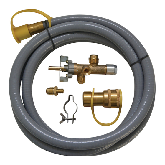
- Page 3 Accessories A: Natural Gas hose and Quick Connect - 1pc B: Natural Gas Valve - 1pc D: Burner tube clamp and wing screw - 1pc E: Quick Connect - 1pc F: Natural Gas Switch Connector with Hex Nut - 1pc Assembly Instructions Tools needed 3/4 wrench X 2...
- Page 4 Step 1 Remove LP hose from LP QDD. LP QDD Remove LP hose Step 2 (1) Remove electrode wires from igniter. (2) Remove the thermocouple wire using a 5/16 open end wrench. (3) Stabilize the LP orifice nozzle using an 11/16 open end wrench and remove metal flex outlet hose using a 3/4 open end wrench.
- Page 5 Step 3 (1) Remove knob and unscrew 2 screws. Put screws and knob aside for re-assembly. (2) Stabilize the LP QDD connector with a 7/8 open end wrench inside the body, r emove the LP QDD nut using another 7/8 open end wrench rotating in opposite directions . (3) Remove the LP valve and metal hoses from the body.
- Page 6 Step 6 (1) Insert valve stem through the hole located in the control panel and use 2 screws to secure. Install control knob. (2) Remove the hex nut from the Natural Gas switch connector and insert the threaded end of the Natural Gas switch connector into the hole from outside of the body.
-
Page 7: Natural Gas Connection
Step 8 (1) Install electrode wires to igniter. (2) Connect the thermocouple wire to the Natural Gas valve using a 5/16 open end wrench. (3) Install the Natural Gas hose to the Natural Gas switch connector. Install NG Gas electrode wires Install Valve thermocouple... - Page 8 PLEASE CALL BOND TOLL FREE #1‐866‐771‐BOND (2663) OR TO BETTER EXPEDITE YOUR REQUEST FEEL FREE TO EMAIL US customer.service@bondmfg.com OR VISITOUR WEBSITE UNDER CUSTOMER SERVICE SUPPORT www.bondmfg.com BOND MANUFACTURING CO., INC. 2516 Verne Roberts Cri., STE H3, Antioch , CA 94509 USA...
- Page 9 Instruc�ons de la trousse de conversion au gaz naturel BIEN LIRE AVANT TOUTE UTILISATION! No d’ar�cle: 52066 DANGER AVERTISSEMENT Ne pas tenter de réparer ou de modifier Si vous sentez une odeur de gaz : ce�e trousse de conversion pour corriger 1.
- Page 10 Le gaz naturel est inflammable et dangereux s’il est manipulé sans précaution. Prendre conscience de ses caractéristiques avant d’utiliser un produit fonctionnant au gaz naturel. o Caractéristiques du gaz naturel : inflammable, explosif sous pression, plus léger que l’air, et se dépose dans les piscines en zones surélevées. o Dans son état naturel, le gaz naturel n’a pas d’odeur. Pour votre sécurité, un odorant a été ajouté. Votre appareil de gaz naturel extérieur a été conçu pour fonctionner au gaz naturel uniquement, et ce, à une pression de colonne d’eau de sept pouces (7 po CE). Des produits chimiques reconnus par l’État de la Californie comme cancérogènes et pouvant provoquer des anomalies congénitales ou autres problèmes sont liés à la combustion du gaz naturel. Vérifiez auprès de votre fournisseur de gaz pour connaître la pression de gaz locale, car elle varie dans certaines régions. Vérifier également auprès de votre compagnie de gaz ou les codes du bâtiment locaux pour connaître les instructions relatives à l’installation d’une conduite d’alimentation en gaz ou appeler un installateur agréé et qualifié. Il est recommandé qu’un robinet manuel d’ARRÊT/MARCHE du gaz soit installé sur la source d’alimentation en gaz : à l’extérieur, après la sortie de la conduite de gaz du mur extérieur et avant le débranchement rapide ou avant que la conduite d’alimentation en gaz ne pénètre dans le sol. L’appareil et son robinet d’arrêt individuel doivent être débranchés de la tuyauterie d’alimentation en gaz pendant tout essai de pression du système lorsque des pressions d’essai sont supérieures à 3,5 kPa (1/2 lb/po²). Cet appareil doit être isolé du système de tuyauterie d’alimentation en gaz en fermant son robinet d’arrêt manuel individuel pendant tout essai de pression du système de tuyauterie d’alimentation en gaz à des pressions inférieures ou égales à 3,5 kPa (1/2 lb/po²). S’assurer que le tuyau de gaz naturel n’entre pas en contact avec une surface haute température ou il pourrait fondre, fuir et provoquer un incendie. Déplacer le tuyau de voies où les gens pourraient y trébucher ou où il peut être accidentellement endommagé. Avertissement! ...
-
Page 11: Instructions De Montage
en gaz doit être coupée à la source et déconnectée de votre appareil extérieur avant la conversion. • Une fois la conversion terminée, votre appareil extérieur doit uniquement être u�lisé avec du gaz naturel. Le robinet, l’orifice et le tuyau sont des�nés au gaz naturel uniquement. •... - Page 12 Étape 1 Retirez le tuyau de GPL du dispositif de dégagement rapide pour GPL. QDD GPL Retirez le tuyau de GPL Étape 2 (1) Retirez les ls d’électrode de l’allumeur. (2) Retirez le l du thermocouple utilisant une clé à fourche de 5/16 po. (3) Stabilisez la buse d’ori ce pour GPL utilisant une clé...
- Page 13 Étape 3 (1) Retirez le bouton et dévissez 2 vis. Mettez les vis et le bouton de côté pour le réassemblage. (2) Stabilisez le raccord du dispositif de dégagement rapide pour GPL avec une clé à fourche de 7/8 po à...
- Page 14 Étape 6 (1) Insérez la tige de manoeuvre à travers le trou situé dans le tableau de commande et utilisez du raccord d’interrupteur pour gaz naturel dans le trou allant de l’extérieur du corps. (3) Stabilisez le raccord d’interrupteur pour gaz naturel avec une clé à fourche de 7/8 po à l’extérieur (4) Stabilisez le raccord d’interrupteur pour gaz naturel avec une clé...
- Page 15 Étape 8 5/16 po. (3) Installez le tuyau de gaz naturel au raccord d’interrupteur pour gaz naturel. Robinet d’électrode Installez le de GN thermocouple Clé à fourche de 5/16 po Tuyau de GN Raccord du gaz naturel : Connecter un robinet d’arrêt manuel à la conduite d’alimentation en gaz. Appliquer un •...
- Page 16 OU AFIN DE MIEUX ACCÉLÉRER VOTRE DEMANDE, N’HÉSITEZ PAS À COMMUNIQUER AVEC NOUS PAR COURRIEL customer.service@bondmfg.com OU CONSULTER NOTRE SITE DANS LA SECTION SOUTIEN TECHNIQUE www.bondmfg.com BOND MANUFACTURING CO. INC. 2516 Verne Roberts Cri., STE H3, Antioch, CA 94509 USA...
- Page 17 Instrucciones del kit de conversión de Gas Natural : 52066 ¡LEER ANTES DE UTILIZAR! No de artículo PELIGRO ADVERTENCIA Si huele a gas: No intente reparar o alterar este kit de conversión para todos los defectos 1. Cierre el paso del gas al aparato.
- Page 18 ¡Advertencia! • El gas natural es inflamable y peligroso si no se manipula adecuadamente Tome conciencia de sus caracterís�cas antes de usar cualquier producto de gas natural. o Caracterís�cas del gas natural: Inflamable, explosivo bajo presión, más liviano que el aire y se almacena en estanques en zonas altas. o En su estado natural, el gas natural no �ene olor.
-
Page 19: Instrucciones De Montaje
• La conversión sólo se debe hacer cuando el aparato esté frío para evitar la posibilidad de quemaduras. Asegúrese de que el control del quemador esté "APAGADO" El suministro de gas se debe apagar en la fuente y desconectar de su aparato exterior antes de la conversión. - Page 20 Paso 1 Retire la manguera para PL del dispositivo de desconexión rápida para PL. QDD PL Retire la manguera para PL Paso 2 (1) Retire los hilos electrodos del encendedor. (2) Retire el cable de termopar utilizando una llave de boca de 5/16 pulg. (3) Estabilice la boquilla tobera para PL utilizando una llave de boca de 11/16 plg.
- Page 21 Paso 3 (1) Retire la perilla y destornille 2 tornillos. Deje los tornillos y la perilla de lado para el reensemblaje. (2) Estabilice el racor del dispositivo de desconexión rápida para PL con una llave de boca de 7/8 pulg. al interior del cuerpo, retire la tuerca del dispositivo de desconexión rápida para PL utilizando la otra llave de boca de 7/8 pulg.
- Page 22 Paso 6 (1) Inserte el vástago de válvula a través del agujero ubicado en el panel de control y utilice 2 tornillos (2) Retire la tuerca hexagonal del conector de interuptor para gas natural y inserte el extremo roscado del conector de interuptor para gas natural en el agujero desde el exterior del cuerpo. (3) Estabilice el conector de interuptor para gas natural con una llave de boca de 7/8 pulg.
- Page 23 Paso 8 (1) Instale los hilos electrodos al encendedor. (2) Conecte el cable del termopar a la válvula para gas natural utilizando una llave de boca de 5/16 pulg. (3) Instale la manguera para gas natural al conector de interuptor para gas natural. Instale los hilos electrodos Válvula Instale...
- Page 24 LLAME AL NÚMERO GRATUITO DE BOND #1-866-771-BOND (2663) O PARA AGILIZAR MÁS SU PEDIDO, PUEDE ENVIARNOS UN CORREO ELECTRÓNICO A customer.service@bondmfg.com O ENTRAR A ATENCIÓN AL CLIENTE EN NUESTRO SITIO WEB www.bondmfg.com BOND MANUFACTURING CO. INC. 2516 Verne Roberts Cri., STE H3, Antioch, CA 94509 USA...
Need help?
Do you have a question about the 52066 and is the answer not in the manual?
Questions and answers