
Summary of Contents for Teleco TVNRG868E04
- Page 1 Control system for garage doors Installer’s instruction manual Product: TVNRG868E04 Doc: T928.01_EN Date: 02/09/2021...
-
Page 2: Product Description
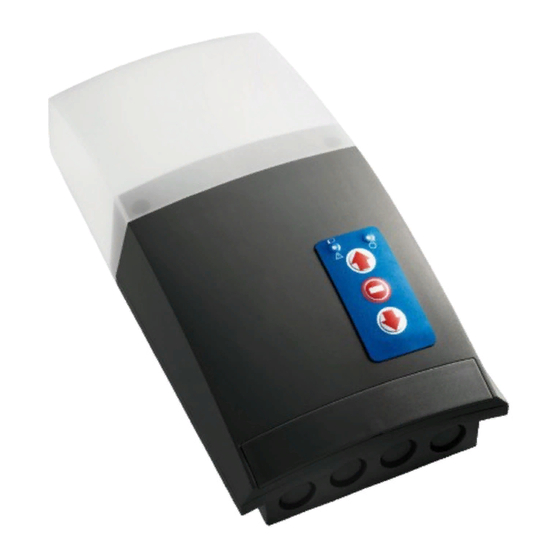
--------------------------------------------------------page 19 4.1 Radio codes memorization Technical specification PRODUCT DESCRIPTION TVNRG868E04 Control unit with integrated radio receiver for the remote control of tubular motors up to 450W, with built-in limit switch, for rolling shutters and rolling doors. FEATURES CONNECTIONS & FUNCTIONING... -
Page 3: Basic Installation
INSTALLATION Complete installation Basic installation 1 - NRG control unit 1 - NRG control unit 2 - Tubular motor (240Vac) 2 - Tubular motor (240Vac) 3 - Hand transmitter 3 - Hand transmitter 4 - Safety edge wireless transmitter 4 - Safety edge wireless transmitte 5 - Wireless security keypad 6 - Wired photocells 7 - External courtesy light... -
Page 4: Mounting The Product
MOUNTING THE PRODUCT BOX DIMENSIONS MOUNTING SIDE OPENING THE COVER 80 mm 290 mm MOUNTING SIDE 85 mm 145 mm 95 mm CONTROL UNIT DIAGRAM Description LED Meaning 1 High voltage terminals Flashing: normal functioning 2 Low voltage terminals ON: transmission error or drained batteries 3 3.15A fuse ON: activated safety alarm, transmission error or drained batteries 4 Aerial connection... - Page 5 Da stampare a colori Da stampare a colori ELECTRICAL CONNECTIONS High voltage terminals Low voltage terminals Wired Push- 240Vac Wired Emergency EARTH MOTOR infrared/8K2 button Line IN photocells STOP (TB) safety edge (TD) see par.2.3 for connections CONNECTION CONNECTION Motor Earth Photocells power supply (+12Vdc) 240Vac Power supply - Earth Safety common (COM)
- Page 6 12 13 14 15 16 17 18 19 20 21 22 23 12 13 14 15 16 17 18 19 20 21 22 23 16- BROWN 17- GREEN WIRED SAFETY DEVICE CONNECTIONS 18- WHITE Infrared (IR) safety edge 16- BROWN 8.2Kohm resistive safety edge 17- GREEN If no wired safety edge is used,...
- Page 7 MOUNTING THE WIRELESS SAFETY SYSTEM (BST24/BST25/BST25S) The system is composed by a radio card (MASTER), plugged in the control unit, and a wireless transmitter (SLAVE) mounted on the door, usually close to the bottom slat, connected to the safety device. The device has got infrared low-consumption barrier (both safety systems), or 8,2KOhm resistive barrier safety edge (only for BST24/BST25).
- Page 8 Installation&Connections Insert the cables. Connect the wires to the clamps. Secure the cable ties INFRARED SAFETY EDGE RESISTIVE SAFETY EDGE BST24 / BST25 BST25S DIP1 = ON DIP1=ON DIP1 = OFF shock sensor shock sensor disabled enabled DIP1 = OFF DIP2 = ON DIP2=ON Infrared test activated for 30 s.
- Page 9 PRELIMINARY CHECK AND INITIAL START-UP A proper connection box should be used to set the limit switch before wiring the motor in the control unit or follow the procedure described on par. 3.1. Start the system up, the buzzer emits 3 quick sounds if the memory is empty or 1 long sound if the memory has radio codes in. After the power-on, the control unit executes only opening commands until the door is fully opened.
-
Page 10: Functioning Mode
MATCHING OF THE WIRELESS SAFETY DEVICE SYSTEM & ACTIVATION/DEACTIVATION • Matching of the wireless safety device system: check that the bottom slat transmitter (SLAVE) is supplied by the batteries, the voltage selector is in the right position and all the connections are correctly made, as decribed at par. 2.5. 1- Push the button of the radio card (MASTER) for 2 seconds, L1 BOTTOM SLAT TRANSMITTER (SLAVE) L1 led Flashing: normal functioning. - Page 11 EXCLUSION OF SAFETY EDGE IN THE LAST 5 CM OF THE CLOSURE In case of uneven floors, it could be necessary deactivating the safety edge in the last part of the closure (not more than 5 cm to comply with the standards) in order to avoid any accidental activation of the safety edge.
- Page 12 TRANSMITTERS & MEMORIZATION TRANSMITTERS 4 channel 3 channel 2 channel 1 channel 7 channel MEMORIZATION TYPE “A” TYPE “C” LIGHT ON/LIGHT OFF OPEN/STOP/CLOSE LIGHT ON/LIGHT OFF for MOTOR OPEN/STOP/CLOSE for LIGHT LIGHT ON/LIGHT OFF OPEN/STOP/CLOSE LIGHT ON/LIGHT OFF OPEN/STOP/CLOSE LIGHT ON/LIGHT OFF OPEN/STOP/CLOSE LIGHT ON/LIGHT OFF OPEN/STOP/CLOSE...
- Page 13 RADIO CODES MEMORIZATION TYPE OF MEMORIZATION continuous sound keep it pressed A Open-Stop-Close B Open (Stop)/Close (Stop) Press the button of the transmitter relative to the code to memorize. intermittent sound C Light On-Light Off Open/Close/Stop/ Light On-Off * The buzzer will make a beep each time the button is pressed. No more than a second should pass between one press to another one.
- Page 14 SINGLE CHANNEL: DOOR STATUS REQUEST (ASK) In case of using bidirectional transmitters it’s possible to receive a feedback about the DOOR STATUS REQUEST (“ASK”) door status, shown by means of the transmitter’s LED: - Red led: open door - Blue led: closed door - Flashing led: missing feedback...
- Page 15 REMOTE MEMORIZATION OF THE FIRST TRANSMITTER Warning: The memory must to be empty in order to perform this procedure. The added transmitter will have the double-channel function (TYPE B). 30 SECONDS TIMEOUT 5 SECONDS TIMEOUT Press 1 time P3 button for 2s The buzzer emits a Press any button of the pair to memorize The buzzer emits a fast continuous sound.
- Page 16 TRANSMITTERS DELETION Press P2 4 times and holt it. The buzzer emits an intermittent sound. Press the button of the transmitter to delete. Once the deletion is successfully completed, the buzzer emits a continuous sound. intermittent sound TYPE OF DELETION keep it pressed Press the button of the transmitter continuos...
- Page 17 AUTO - CLOSE TIME SETTING This procedure configures the time lapse between complete opening and the automatic closure (if enabled). The default time is 30 seconds. It is possible to set the time from 5 seconds to 180 seconds. 30 seconds timeout 5 seconds timeout START STOP...
- Page 18 MOTOR TORQUE CONTROL The procedure activates or deactivates the motor torque control. The control unit will costantly check the level of current required by the motor during the movement in order to detect any anomaly in the normal operation of the door. In case of excessive effort, the control unit will stop and reverse the manoeuvre. 30 seconds timeout DEACTIVATED keep it...
-
Page 19: Other Possible Issues
TROUBLESHOOTING (WHAT TO DO IF...) Acoustic signals from the control unit Sequence Meaning Solution 1 costant beep (continuous or Faulty control unit Replace the control unit intermittent) 2 beeps Motor problem - Set the limit switches - The thermal protection could be activated. Wait while the motor cools down. - Check the motor connection - Test the motor separately by means of a proper tool 3 beeps at startup... -
Page 20: Technical Specifications
In the view of a constant development of their products, the manufacturer reserves the right for changing technical data and features without prior notice. The manufacturer, Teleco Automation s.r.l, declares that the type of radio equipment is compliant with Directive 2014/53/EU. The full text of the EU compliance declaration is available at the following Internet address: www.telecoautomation.com/ce.
Need help?
Do you have a question about the TVNRG868E04 and is the answer not in the manual?
Questions and answers