
Summary of Contents for Blohm + Voss Oil Tools GraySpin Mark 40
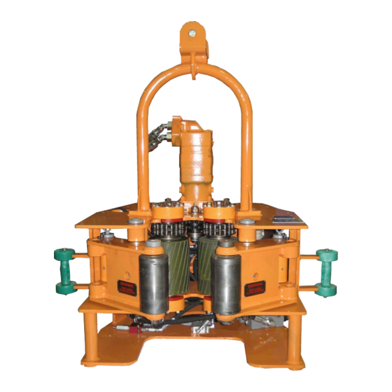
- Page 1 Blohm + Voss Oil Tools, LLC GraySpin Mark 40 Hydraulic Drill Pipe Spinner With and without Hydraulic Lift Technical Documentation...
- Page 2 Warnings and Notes information contained herein. and specifications without Limited Warranty WARNING: A “WARNING” Blohm + Voss Oil Tools, LLC, announcement. The warranty provided will INDICATES A DEFINITE will not be held liable for be void if the Mark 40 is:...
-
Page 3: Revision History Table
Safety issues WARNING: ONE SHOULD WARNING: FAILURE TO WARNING: KEEP HANDS WARNING: ALWAYS USE AVOID CREATING IGNITION CONDUCT ROUTINE AND ARMS CLEAR OF LIFTING APPARATUS SOURCES, LIKE HEAT, AS A MAINTENANCE COULD ALL MOVING PARTS (SLINGS, CABLES, RESULT OF THE USE OF THE RESULT IN EQUIPMENT WHEN CONNECTING, SHACKLES AND THE... -
Page 4: Table Of Contents
TABLE OF CONTENTS Revision History Table TABLE OF CONTENTS INTRODUCTION About This Manual Using The Manual Location of I.D. Numbers Safety First Buying Replacement Parts and Repair Warnings SPECIFICATIONS Specifications Hydraulic Requirements Cylinder Data Palletized Shipping Data Operational Settings INSTALLATION Hanging the Spinner Attaching to the Mast Attaching the Fixed Line... - Page 5 Grease Quality Hydraulic Oil Quality Primary Hydraulic Oil Shell Tellus® Oil Premium 68 Lubrication Lubrication Chart Lubrication Points ASSEMBLIES MARK 40 MARK 40 CASE ASSEMBLY 9MK40CASEASSM MOTOR MOUNT PLATE SUB ASSEMBLY 9G1084-3 HYDRAULIC MOTOR 9G1001-3 IDLER SPROCKET SUB ASSEMBLY 9G1083-1 DRIVE CHAIN 9G8000 RIGHT HAND DOOR...
-
Page 6: Introduction
INTRODUCTION... -
Page 7: About This Manual
The Mark 40 offers the ultimate in simplicity and rugged design. Designed to be compact and self contained; the Mark 40 does not require a stand-alone power pack. All the gripping pressure and spinning torque are generated at the drill pipe spinner. In standard rig installations a spring hanger assembly is provided. -
Page 8: Safety First
Safety First Regardless of how enthusiastic you may be about beginning the job at hand, take the time to ensure that your safety is not jeopardized. A moment’s lack of attention may result in an accident, as can failure to observe certain simple safety precautions. The possibility of an accident will always exist. - Page 9 Keep hands and arms clear of all moving parts when connecting, disconnecting or operating the unit. When servicing the unit, be sure all power is off and supply lines are disconnected. Always use lifting apparatus (slings, cables, shackles and the like) that have been inspected are in good condition and are of the proper size.
-
Page 10: Specifications
SPECIFICATIONS... -
Page 11: Specifications
Specifications Hydraulic Requirements Hydraulic supply pressure (max.) 2,500 psi (17.23 mPa) - 172.36 bar Hydraulic supply pressure (min.) 1,750 psi (12.06 mPa) - 120.65 bar Hydraulic flow rate required 20 gpm (75.7 lpm) Supply connection (min.) 1” hose with 1/2” inlet Return connection (min.) 1”... - Page 12 Figure 2 Power Weight Requirements Torque 32.5 in 28.5 in 13.5 in 55 in 1,250 lbs 1,750 psi 1,285 ft-lbs (12,065.82 kPa) 82.6 cm 72.4 cm 34.2 cm 139.7 cm 568.2 kg 120.65 bar 1,912 Nm...
-
Page 13: Installation
INSTALLATION... -
Page 14: Hanging The Spinner
Hanging the Spinner The GraySpin Mark 40 should be hung using a wire rope that is ½” or greater and that is in accordance with acceptable practices. Attach the wire rope through the shackle at the top of the spring hanger assembly. -
Page 15: Connecting The Hydraulic Line
Figure 4 Pipe Size Adjustment The GraySpin Mark 40 will initially be set with the arm to cylinder connecting pin placed in the rear position. This will accommodate most pipe sizes. If it is necessary to move the pin to the front position, slowly activate the door valve until the pin is lined up past the front of the top plate. -
Page 16: Operations
OPERATIONS... -
Page 17: Correct Height
Correct Height Before starting operation with the Mark 40, please make sure the pipe size set up matches the appropriate pipe O.D. The Mark 40 will initially be set with the arm cylinder connecting pin placed in the rear position. This will accommodate most pipe sizes. Position of the Doors The doors need to be open to position the tool. -
Page 18: Operation
Operation 1. Check chain for tightness. Do not allow for slack. Motor capscrews must be tight. 2. With the doors open, swing the Mark 40 into position on the drill pipe. Figure 9 3. Position the Mark 40 on the pipe approximately 12”... -
Page 19: Hyraulic Lift Cylinder Operation (Optional)
Hyraulic Lift Cylinder Operation (Optional) Please refer to the instalation section for proper installation procedures such as attaching to the mast, attaching the fixed line, back up cables, connecting the hydraulic line, balancing screw and pipe size adjustment. Check chain for tightness. Do not allow for slack. Motor capscrews must be tight. The operation of the Mark 40 is very simple. -
Page 20: Trouble Shooting
Trouble Shooting Problem: Cause: Solution: Excessive noise • Mechanical vibrations. • Repair worn or damaged components. levels. • Motor incorrectly aligned. • Align correctly. • Air in circuit. • Bleed circuit. • Dumping over relief. • Adjust relief valve or pressure valve. Motor •... - Page 21 Trouble Shooting Incorrect sense • Tubes connected • Reverse the connection. of rotation. incorrectly. • Wash drive rollers with long handle Drive rollers slip • Rollers are greasy and/or bristle brush, soap and water. on drill pipe. oil coated. • Increase pressure to clamping •...
-
Page 22: Maintenance & Inspection
MAINTENANCE & INSPECTION... -
Page 23: Chain (9G8000)
The GraySpin Mark 40 has been designed with the ease of repair as an important feature. The Mark 40 is comprised of modular components so that any problem can be easily detected. Every component can be either repaired or replaced in the field keeping down time to a minimum. -
Page 24: Drive Rollers
Drive Rollers To remove one or both of the drive rollers the following procedure should be used: 1. Remove chain (See Chain Removal) 2. Remove one or both pressure arm assemblies. This is accomplished by removing the locking capscrew and pulling the cylinder pin. -
Page 25: Cylinder Repair
Cylinder Repair Cylinder removal on the GraySpin Mark 40 Hydraulic Spinner is accomplished addressing the right hand cylinder first. Remove the arm/cylinder pin and pivot the arm forward. The clevis pin at the cylinder rear can be removed by first taking off the spiral retaining ring located at the bottom of the pin. -
Page 26: Hydraulic Oil Quality
Hydraulic Oil Quality BVOT recommends a mineral based hydraulic Note: Holes in the bottom of the spinner case are provided in order to drive clevis pins out if necessary. oil, ISO 68 or equivalent for primary use in temperature ranges between 65° - 95° F (18° - 35°... -
Page 27: Lubrication
Lubrication The Mark 40 should be inspected and greased each week. For higher ambient temperature up to 86° Fahrenheit (30° Celsius) we recommend to use NLGI grade 2. Lubrication Chart Location Frequency Type Quantity (4 locations) Do not over Bearing Caps Daily Grease grease and burst seals. -
Page 28: Lubrication Points
Lubrication Points Figure 18... -
Page 29: Assemblies
ASSEMBLIES... -
Page 30: Mark 40
MARK 40 Figure 19 Item Part Number Description Qty. 9MK40CASEASSM CASE ASSEMBLY 9G1084-3 MOTOR MOUNT PLATE SUB ASSEMBLY 9G1083-1 IDLER SPROCKET SUB ASSEMBLY 9G-8000 DRIVE CHAIN 9G1080-31 RIGHT HAND DOOR ASSEMBLY 9G1080-32 LEFT HAND DOOR ASSEMBLY 9G1081-30 DRIVE ROLLER SUB ASSEMBLY 9G1081-9 BEARING CAP ASSEMBLY 9G1086-2... -
Page 31: Mark 40 Case Assembly 9Mk40Caseassm
MARK 40 CASE ASSEMBLY 9MK40CASEASSM Figure 22 Figure 20 Figure 23 Figure 24 Figure 21 Figure 25... - Page 32 MARK 40 CASE ASSEMBLY 9MK40CASEASSM Item Part Number Description Qty. 9MK40CASE MARK 40 CASE HYDRAULIC 9G1030-5 HYD. PRESS / RETURN TAG 9G1030-6 GRAYSPIN SN TAG 9G1030-8 DO NOT RUN ON TOOL JOINT TAG 9G1030-10 READ MANUAL TAG 9BN41203 1/8 X 1/4 RIVET 9913144-91 HANGER BOLT 9BN1137190...
-
Page 33: Motor Mount Plate Sub Assembly 9G1084-3
MOTOR MOUNT PLATE SUB ASSEMBLY 9G1084-3 Figure 26... - Page 34 MOTOR MOUNT PLATE SUB ASSEMBLY 9G1084-3 Item Part Number Description Qty. 9BN0118911 HEX HEAD CAP SCREW 9BN1133895 SPLIT LOCKWASHER 9G1039 MOTOR SHAFT CAP 9G1017 DRIVE SPROCKET 9BN1125537 SET SCREW 9G1043 SPROCKET KEY 9G1040 SPROCKET SPACER 9G1028-1 MOTOR MOUNT 9G1036 MOTOR MOUNT BUSHING 9BN0118916 HEX HEAD CAP SCREW 9BN1137084...
-
Page 35: Hydraulic Motor 9G1001-3
HYDRAULIC MOTOR 9G1001-3 Figure 27 Item Part Number Description Qty. 9MK20H7 HOSE NO. 7 9MK20H8 HOSE NO. 8 9MK20H13 HOSE NO. 13 (CASE DRAIN) 9BN1137084 NYLON LOCK NUT 9BN1133895 SPLIT LOCKWASHER 9BN0115363 3/4-10 X 2-1/2 HHCS 9BN1133898 3/4 SPLIT LOCKWASHER 9BN1133820 3/4 SAE FLAT WASHER... -
Page 36: Idler Sprocket Sub Assembly 9G1083-1
IDLER SPROCKET SUB ASSEMBLY 9G1083-1 Figure 28 Item Part Number Description Qty. 9BN60107 GREASE ZERK 9G2111-9 NYLOCK INSERTED LOCKNUT 9G2111-11 FLAT WASHER 9G1008 IDLER SPROCKET SHAFT 9G1005 IDLER SPROCKET 9G1013-2 THRUST WASHER 9G1016 IDLER SPACER 9G2111-10 NYLOCK LOCKNUT 9BN65107 COTTER PIN... -
Page 37: Drive Chain 9G8000
DRIVE CHAIN 9G8000 Figure 29 Item Part number Description 9G8000 DRIVE CHAIN 9G8000-RK DRIVE CHAIN REPAIR KIT... -
Page 38: Right Hand Door
RIGHT HAND DOOR Figure 30... -
Page 39: 4" Od Pressure Roller Assembly 9G1082-3
4” OD PRESSURE ROLLER ASSEMBLY 9G1082-3 Item Part Number Description Qty. 9G1082-3 4” OD PRESSURE ROLLER ASSEMBLY 9GAN1803 THRUST WASHER SEAL 9G1013-6 THRUST WASHER 9GMR32 BEARING 9G1014-1 SPACER 9G1300 BUSHING 9G1012-2 PRESSURE ROLLER RIGHT ARM SUB ASSEMBLY 9G1080-31 Item Part Number Description Qty. -
Page 40: Left Hand Door
LEFT HAND DOOR Figure 31... -
Page 41: Left Arm Sub Assembly 9G1080-32
4” OD PRESSURE ROLLER ASSEMBLY 9G1082-3 Item Part Number Description Qty. 9G1082-3 4” OD PRESSURE ROLLER ASSEMBLY 9GAN1803 THRUST WASHER SEAL 9G1013-6 THRUST WASHER 9GMR32 BEARING 9G1014-1 SPACER 9G1300 BUSHING 9G1012-2 PRESSURE ROLLER LEFT ARM SUB ASSEMBLY 9G1080-32 Item Part Number Description Qty. -
Page 42: Drive Roller Sub Assembly 9G1081-30
DRIVE ROLLER SUB ASSEMBLY BEARING CAP ASSEMBLY 9G1081-30 9G1081-9 Figure 32... -
Page 43: Bearing Cap Assembly 9G1081-9
DRIVE ROLLER SUB ASSEMBLY 9G1081-30 Item Part Number Description Qty. 9BN0118916 HEX HEAD CAP SCREW 9G1009 BEARING CAP 9G1009-1 BEARING CAP INSERT 9G1007 DRIVE ROLLER SPROCKET 9BN1125539 SET SCREW 9G1026-30 DRIVE ROLLER 9G1010 DRIVE ROLLER SHAFT 9G1013-3 WASHER 9G2300-225 EXTERNAL RETAINING RING 9G1029-1 SHAFT KEY 9G1013-5... -
Page 44: Hydraulic Cylinder Sub-Assembly 9G1086-1
HYDRAULIC CYLINDER SUB-ASSEMBLY 9G1086-1 Figure 33 Item Part Number Description Qty. 9G5004 ARM CYLINDER 9G5002-2 CYLINDER CLEVIS PIN 9G2440-2 SAFETY PIN 9G1023-30 CYLINDER CLEVIS 9G1025 CLEVIS SPACER 9BN60105 1/4-28 GREASE ZERK STRAIGHT 9HC410C50X 1/4” JIC X 5/8” ORB 90° 9HC410F50X 1/4”... -
Page 45: Hydraulic Control Valve Assembly (Door & Motor) 9G6005-1
HYDRAULIC CONTROL VALVE ASSEMBLY (DOOR & MOTOR) 9G6005-1 Figure 34 Item Part Number Description Qty. 9G6005 TWO BANK CLOSED HYDRAULIC VAVLE 9G6005-LK LINKAGE KIT 9G6005-7 DOOR - HANDLE 9G6005-7 MOTOR - HANDLE 9G6005-8 LOCK OUT BRACKET 9G6005-9 SPACERS... -
Page 46: Three Bank Valve Assembly 9G6005-40
THREE BANK VALVE ASSEMBLY 9G6005-40 Figure 35 Item Part Number Description Qty. INLET - PRESSURE 9G6005-2 OPEN CENTER PLUG FOR G6005 9G6005-7 LIFT - GOLD 9G6005-7 DOORS - RED 9G6005-7 MOTOR - BLACK 9G6005-8 LOCK OUT FOR 9G6005-1 OUTLET - RETURN 9G6005-9 SPACER FOR V20 GRESEN VALVE 9G6005-LK... -
Page 47: Hose Connections - Hydraulic Door Cylinder
HOSE CONNECTIONS - HYDRAULIC DOOR CYLINDER Figure 37 HOSE CONNECTIONS - FRONT SIDE Figure 36... -
Page 48: Hose Connections - Back Side
HOSE CONNECTIONS - BACK SIDE Figure 39 STERLING RELIEF VALVE & BODY 9G6011 RETURN LINE PRESSURE LINE Figure 38... -
Page 49: Hose Kit 9G10002
HOSE KIT 9G10002 Item Part Number Description Qty. 9MK40H1 HOSE NO. 1 9MK40H2 HOSE NO. 2 9MK40H3 HOSE NO. 3 9MK40H4 HOSE NO. 4 9MK40H5 HOSE NO. 5 9MK40H6 HOSE NO. 6 9MK40H7 HOSE NO. 7 9MK40H8 HOSE NO. 8 9MK40H9 HOSE NO. -
Page 50: Hydraulic Schematic
HYDRAULIC SCHEMATIC Figure 40... -
Page 51: Tri-Spring Hanger Assembly 9G-13805
TRI-SPRING HANGER ASSEMBLY 9G-13805 Figure 41 Item Part Number Description Qty. 9G1032 HEAVY DUTY HANGER SPRING 9G1034-1 TRI SPRING HANGER BRACKET 9G1033-1 SPRING HANGER SAFETY CABLE 9G2450-1 SHACKLE 9G2450-2 SHACKLE... -
Page 52: Supply And Return Hoses 9G10002
SUPPLY AND RETURN HOSES 9G10002 Figure 42 Item Part Number Description Qty. 9MK40H1 SUPPY HOSE (20’ x 1/2”) 9MK40H2 RETURN HOSE (20’ x 3/4”) 9HCPVEP15 3/4 ALUM PLUG / CHAIN 9HCPVEP17 1 ALUM PLUG / CHAIN 9HCFVEP15 3/4 FLAT FACE QDC COUPLER 9HCFVEP17 1 FLAT FACE QDC COUPLER... -
Page 53: Lift Cylinder 9G5007
LIFT CYLINDER 9G5007 Figure 43 Figure 44 Item Part Number Description Qty. 9G5007 18” HYDRAULIC LIFT CYLINDER MK40H5 MARK 40 HOSE NO. 5 HCMVEP7 1/4 STUCCHI MALE (NIPPLE) QDC HCFVEP7 1/4 STUCCHI FEMALE (COUP) QDC HC84CR 1/2 MPT X 1/4 MPT 90° 9HC8HHP 1/2 MPT COUNTERSUNK PLUG 9G2450-2... - Page 54 SPARE PARTS...
- Page 55 RECOMMENDED SPARE PARTS FOR ONE YEAR OF USE Item Part Number Description Qty. 9G3001-1 SPHERICAL BEARING 9G5500-1 BEARING CAP SEAL 9G1026-30 MARK 40 DRIVE ROLLER 9G2300-225 EXTERNAL RETAINING RING 9G2351-314 RETAINING RING 9G1013-3 DRIVE ROLLER THRUST WASHER 9G1013-2 PIVOT ARM THRUST WASHER 9G3000-2 IDLER SPROCKET BRONZE BEARING 9G8000...
- Page 56 INDEX...
- Page 57 1/4-28 90° ZERK 1 ALUM PLUG / CHAIN 1 FLAT FACE QDC COUPLER 3 1/2” PRESSURE ROLLER 3/4-10 X 2-1/2 HHCS 3/4 ALUM PLUG / CHAIN 3/4 FLAT FACE QDC COUPLER 3/4 SAE FLAT WASHER 3/4 SPLIT LOCKWASHER 4” OD PRESSURE ROLLER ASSEMBLY 39, 41 9BN41203 39, 41...
- Page 58 9G1013-2 36, 39, 41 9G1013-3 9G1013-5 9G1013-6 39, 41 9G1014-1 39, 41 9G1015 39, 41 9G1016 9G1017 9G1021-31 39, 41 9G1023-10 9G1023-30 9G1025 9G1026-30 9G1028-1 9G1029-1 9G1029-2 9G1030-2 39, 41 9G1032 9G1033-1 9G1034-1 9G1036 9G1039 9G1040 9G1041 9G1043 9G1045 9G1081-9 9G1081-30 42, 43 9G1082-3...
- Page 59 9G2450-2 9G5001 9G5002-2 9G5004 9G6005 30, 45 9G6005-7 9G6005-8 9G6005-9 9G6005-LK 9G6011 48, 49 9G8000 27, 37 9G8000-RK 9G10002 49, 52 9G162006 39, 41 9G202632 39, 41 9GAN1803 39, 41, 55 9GMR32 39, 41 9HC48CTX 9HC48FTX 9HC4267HPP 9HCFVEP15 9HCFVEP17 9HCPVEP15 9HCPVEP17 9MK20H7 9MK20H8...
- Page 60 9MK40H12 9MK40H13 9MK40H14 ARM CYLINDER BEARING 39, 41, 42, 43 BEARING CAP BEARING CAP ASSEMBLY 42, 43 BEARING CAP INSERT BRONZE BEARING 39, 41 BUSHING 39, 41 34, 39, 41, 42, 43 CASE DRAIN CLEVIS SHAFT ASSEMBLY 39, 41 CLEVIS SPACER COTTER PIN CYLINDER CLEVIS CYLINDER CLEVIS PIN...
- Page 61 HEAVY DUTY HANGER SPRING HEX HEAD CAP SCREW 34, 43 HOSE NO. 1 HOSE NO. 2 HOSE NO. 3 HOSE NO. 4 HOSE NO. 5 49, 53 HOSE NO. 6 HOSE NO. 7 35, 49 HOSE NO. 8 35, 49 HOSE NO.
- Page 62 MOTOR HOSE MOTOR MOUNT MOTOR MOUNT BUSHING MOTOR MOUNT PLATE SUB ASSEMBLY 33, 34, 35 MOTOR SHAFT CAP MPT 90 MPT STRAIGHT NYLOCK INSERTED LOCKNUT NYLON LOCK NUT 34, 35 PIVOT ARM SHAFT 39, 41 PIVOT ARM THRUST WASHER 39, 41 PRESSURE ROLLER 39, 41 PRESSURE ROLLER ASSEMBLY...
- Page 63 SPROCKET SPACER 34, 43 SPROKET KEY STERLING RELIEF VALVE & BODY SUPPLY AND RETURN HOSES SUPPY HOSE (20’ x 1/2”) THRUST WASHER 36, 39, 41, 55 THRUST WASHER SEAL 39, 41, 55 TRI SPRING HANGER BRACKET TWO BANK CLOSED HYDRAULIC VAVLE TWO BANK CLOSED HYD.
- Page 64 India Brazil Italy Azerbaijan Mexico Columbia Manufacturer & Agents World Wide Blohm + Voss Oil Tools, LLC Blohm + Voss Oil Tools GmbH Premier Sea & LandPte Ltd Sharjah 11355 FM 830 Hermann-Blohm-Straße 2 54 Loyang Way United Arab Emirates...
Need help?
Do you have a question about the GraySpin Mark 40 and is the answer not in the manual?
Questions and answers