Table of Contents
Advertisement
Quick Links
650EFC
USER'S MANUAL
M/B For Socket 478 Pentium 4 Processor
NO. G03-650EFC1A
Release date: April 2003
Trademark:
* Specifications and Information contained in this documentation are furnished for information use only, and are
subject to change at any time without notice, and should not be construed as a commitment by manufacturer.
Advertisement
Table of Contents

Summary of Contents for Develop 650EFC
- Page 1 650EFC USER'S MANUAL M/B For Socket 478 Pentium 4 Processor NO. G03-650EFC1A Release date: April 2003 Trademark: * Specifications and Information contained in this documentation are furnished for information use only, and are subject to change at any time without notice, and should not be construed as a commitment by manufacturer.
-
Page 2: Table Of Contents
TABLE OF CONTENT USER’S NOTICE ......................1 MANUAL REVISION INFORMATION ................1 COOLING SOLUTIONS ....................1 CHAPTER 1 INTRODUCTION OF 650EFC MOTHERBOARD 1-1 FEATURE OF MOTHERBOARD ................2 1-2 SPECIFICATION .....................3 1-3 PERFORMANCE LIST....................4 1-4 LAYOUT DIAGRAM & JUMPER SETTING............5 CHAPTER 2 HARDWARE INSTALLATION 2-1 HARDWARE INSTALLATION STEPS ..............7... -
Page 3: User's Notice
REPRODUCED, TRANSMITTED OR TRANSLATED INTO ANY LANGUAGE IN ANY FORM OR BY ANY MEANS WITHOUT WRITTEN PERMISSION OF THE MANUFACTURER. THIS MANUAL CONTAINS ALL INFORMATION REQUIRED TO USE 650EFC MOTHER-BOARD AND WE DO ASSURE THIS MANUAL MEETS USER’S REQUIREMENT BUT WILL CHANGE, CORRECT ANY TIME WITHOUT NOTICE. -
Page 4: Chapter 1 Introduction Of 650Efc Motherboard
Introduction of 650EFC Motherboard 1-1 Feature of motherboard The 650EFC motherboard is design for use Intel Pentium 4 Processor in 478 Pin Package Processor with the SiS 651 Chipset delivers a high performance and professional desktop platform solution. Which utilize the Socket 478 design (Support Hyper Threading CPU) and the memory size expandable to 2.0GB. -
Page 5: Specification
1-2 Specification Spec Description ∗ Mini ATX form factor 6 layers PCB size: 17.6x24.0cm Design ∗ SiS 651 North Bridge Chipset Chipset ∗ SiS 962L/962 MuTIOL Media I/O Chipset ∗ Support Intel Pentium 4 478 Pin package utilizes Flip-Chip Pin CPU Socket (mPGA478B Socket) Grid Array (FC-PGA2) package processor... -
Page 6: Performance List
1-3 Performance List The following performance data list is the testing result of some popular benchmark testing programs. These data are just referred by users, and there is no responsibility for different testing data values gotten by users (the different Hardware & Software configuration will result in different benchmark testing results.) Performance Test Report CPU:... -
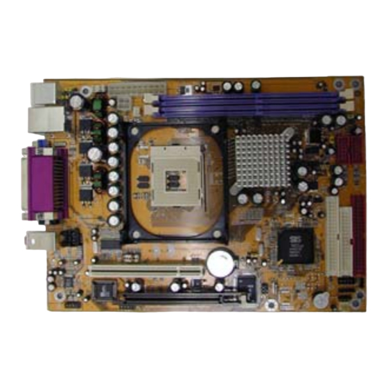
Page 7: Layout Diagram & Jumper Setting
1-4 Layout Diagram & Jumper Setting PRINT 6-Channel Speaker PS/2 Mouse LINE-IN PS/2 Keyboard LINE-OUT SPDIF-OUT ATX 12V Power Conn. Remote Control Header (JP5) option K/B Power ON Jumper (JP6) ATX Power Conn. PS2 KB/Mouse Port DIMM Socket X2 USB Power ON Jumper (JP7) USB Power ON Jumper USB Port/LAN Connector... - Page 8 Jumpers Jumper Name Description Page CMOS RAM Clear 3-pin Block Keyboard Power On Enable/Disabled 3-pin Block JP7, JP8, JP104 USB Power On Enable/Disabled 3-pin Block Front Side Bus Frequency Setting 10-pin Block Connectors Connector Name Description Page ATXPWR ATX Power Connector 20-pin Block P.12 ATX12V...
-
Page 9: Hardware Installation Steps
Chapter 2 Hardware installation 2-1 Hardware installation Steps Before using your computer, you had better complete the following steps: 1. Check motherboard jumper setting 2. Install CPU and Fan 3. Install System Memory (DIMM) 4. Install Expansion cards 5. Connect IDE and Floppy cables, Front Panel /Back Panel cable 6. - Page 10 When setting Enabled you can using keyboard by key in password to power on system. 1-2 closed K/B Power ON Disable 2-3 closed K/B Power ON Enabled (Default) Keyboard Power On Setting (3) USB Power On function Enabled/Disabled: JP7, JP8, JP104 JP104 JP104 1-2 closed:...
-
Page 11: Glossary
2-3 Install CPU 2-3-1 Glossary Chipset (or core logic) - two or more integrated circuits which control the interfaces between the system processor, RAM, I/O devises, and adapter cards. Processor slot/socket - the slot or socket used to mount the system processor on the motherboard. -
Page 12: Install Memory
The CPU that comes with the motherboard should have a cooling FAN attached to prevent overheating. If this is not the case, then purchase a correct cooling FAN before you turn on your system. WARNING! Be sure that there is sufficient air circulation across the processor’s heatsink and CPU cooling FAN is working correctly, otherwise it may cause the processor and motherboard overheat and damage, you may install an auxiliary cooling FAN, if necessary. -
Page 13: Expansion Card
NOTE! When you install DIMM module fully into the DIMM socket the eject tab should be locked into the DIMM module very firmly and fit into its indention on both sides. WARNING! For the DDR SDRAM CLOCK is set at 133MHz, use only DDR266-compliant DDR Modules. -
Page 14: Interrupt Request Table For This Motherboard
ACPI Mode when enabled 10 * IRQ Holder for PCI Steering 11 * IRQ Holder for PCI Steering 12 * PS/2 Compatible Mouse Port Numeric Data Processor 14 * Primary IDE Channel 15 * Secondary IDE Channel * These IRQs are usually available for ISA or PCI devices. 2-5-3 Interrupt Request Table For This Motherboard Interrupt request are shared as shown the table below: INT A INT B INT C INT D INT E... - Page 15 Pin 1 ROW2 ROW1 3.3V 3.3V -12V 3.3V Soft Power On Power OK +5V (for Soft Logic) +12V (2) ATX 12V Power Connector (4-pin block) : ATX12V This is a new defined 4-pins connector that usually comes with ATX Power Supply. The ATX Power Supply which fully support Pentium 4 processor must including this connector for support extra 12V voltage to maintain system power consumption.
- Page 16 Floppy drive Connector (34-pin block): FDD This connector supports the provided floppy drive ribbon cable. After connecting the single plug end to motherboard, connect the two plugs at other end to the floppy drives. Pin 1 Floppy Drive Connector (10) Primary IDE Connector (40-pin block): IDE1 This connector supports the provided IDE hard disk ribbon cable.
-
Page 17: Headers
IDE2 Pin 1 Secondary IDE Connector • Two hard disks can be connected to each connector. The first HDD is referred to as the “Master” and the second HDD is referred to as the “Slave”. • For performance issues, we strongly suggest you don’t install a CD-ROM or DVD-ROM drive on the same IDE channel as a hard disk. - Page 18 OC (Over Current) USB1 USB2 +DATA +DATA +DATA +DATA DATA DATA DATA DATA Pin 1 Pin 1 USB Port Headers IDE Activity LED: HD-LED This connector connects to the hard disk activity indicator light on the case. Reset switch lead: RESET This 2-pin connector connects to the case-mounted reset switch for rebooting your computer without having to turn off your power switch.
- Page 19 CPUFAN SFAN FAN Headers (10) IR infrared module Headers (5-pin) : IR This connector supports the optional wireless transmitting and receiving infrared module. You must configure the setting through the BIOS setup to use the IR function. Pin 1 VCC5 IRTX IRRX IR infrared module Headers...
-
Page 20: Starting Up Your Computer
This header is option for connect Remote Control Receiver, the default setting is for On board Keyboard and PS/2 Mouse. The Setting are pin #3 & #5, #7 & #9, #4 & #6, #8 & #10 are closed by jumper. When use the Remote Control Receiver please remove these jumpers. - Page 21 If you do not see any thing within 30 seconds from the time you turn on the power. The system may have failed on power-on test. Recheck your jumper settings and connections or call your retailer for assistance. Beep Meaning One short beep when displaying logo No error during POST Long beeps in an endless loop...
-
Page 22: Entering Setup
• Press ↑ ↓ ← → (up, down, left, right) to choose, in the main menu, the option you want to confirm or to modify. • Press <F10> when you have completed the setup of BIOS parameters to save these parameters and to exit the BIOS Setup menu. - Page 23 Standard CMOS Features Miscellaneous Control Advanced BIOS Features Load optimized Defaults Advanced Chipset Features Load Standard Defaults Integrated Peripherals Set Supervisor Password Power Management Setup Set User Password PnP/PCI Configurations Save & Exit Setup PC Health Status Exit Without Saving ↑↓→←...
-
Page 24: Standard Cmos Features
Use this menu to load the BIOS default values for the stable performance system operation that are factory settings for normal use. Set Supervisor/User Password Use this menu to set User and Supervisor Passwords. Save & Exit Setup Save CMOS value changes to CMOS and exit setup. Exit Without Saving Abandon all CMOS value changes and exit setup. -
Page 25: Advanced Bios Features
Year The year depends on the year of the BIOS. Time The time format is <hour><minute><second>. Primary Master/Primary Slave Secondary Master/Secondary Slave Press PgUp/<+> or PgDn/<–> to select Manual, None, Auto type. Note that the specifications of your drive must match with the drive table. The hard disk will not work properly if you enter improper information for this category. - Page 26 ↑↓→← Move Enter:Select +/-/PU/PD:Value F10:Save ESC:Exit F1:General Help F5:Previous Values F6:Optimized Defaults F7:Standard Defaults Anti-Virus Protection Allows you to choose the VIRUS Warning feature for IDE Hard Disk boot sector protection. If this function is enabled and someone attempt to write data into this area, BIOS will show a warning message on screen and alarm beep.
-
Page 27: Advanced Chipset Features
Keystrokes repeat at a rate determined by the keyboard controller. When enabled, the typematic rate and typematic delay can be selected. The settings are: Enabled/Disabled. Typematic Rate (Chars/Sec) Sets the number of times a second to repeat a keystroke when you hold the key down. The settings are: 6, 8, 10, 12, 15, 20, 24, and 30. -
Page 28: Agp Function Settings
This option determines the effective size of the graphics aperture used in the particular PAC configuration. The AGP aperture is memory-mapped, while graphics data structure can reside in a graphics aperture. The aperture range should be programmed as not cacheable in the processor cache, accesses with the aperture range are forwarded to the main memory, then PAC will translate the original issued address via a translation table that is maintained on the main memory. -
Page 29: Integrated Peripherals
CMOS Setup Utility – Copyright(C) 1984-2003 Award Software AGP Function Settings AGP Transfer Mode Auto Item Help AGP Fast Write Disabled AGP Aperture Size 64MB AGP Aperture Write Combining Enabled Menu Level >> AGP Driving Control Auto AGP Driving Value System Share Memory Size 32MB ↑↓→←... -
Page 30: Onchip Device Function
Primary Slave Auto Menu Level >> Secondary Master PIO Auto Secondary Slave Auto Primary Master UltraDMA Auto Primary Slave UltraDMA Auto Secondary Master UltraDMA Auto Secondary Slave UltraDMA Auto IDE DAM Transfer Access Enabled IDE Burst Mode Enabled IDE HDD Block Mode Enabled Delay For HDD (Secs) ↑↓→←... - Page 31 ↑↓→← Move Enter:Select +/-/PU/PD:Value F10:Save ESC:Exit F1:General Help F5:Previous Values F6:Optimized Defaults F7:Standard Defaults USB Controller Select Enabled if your system contains a Universal Serial Bus (USB) controller and you have a USB peripherals. The settings are: Enabled, Disabled. USB Keyboard Legacy Support Select Enabled if your system contains a Universal Serial Bus (USB) controller and you have a USB keyboard.
-
Page 32: Power Management Setup
Parallel Port Mode : Standard Parallel Port : Enhanced Parallel Port : Extended Capability Port SPP/EPP/ECP/ECP+EPP To operate the onboard parallel port as Standard Parallel Port only, choose “SPP.” To operate the onboard parallel port in the EPP modes simultaneously, choose “EPP.” By choosing “ECP”, the onboard parallel port will operate in ECP mode only. -
Page 33: Pm Wake Up Events
The settings are: 3, 4, 5, 7, 9, 10, 11, NA. Power Button Function Pressing the power button for more than 4 seconds forces the system to enter the Soft-Off state. The settings are: Delay 4 Sec, Instant-Off. PM Wake Up Events Please refer to section 3-8-1 3-8-1 PM Wake Up Events CMOS Setup Utility –... -
Page 34: Pnp/Pci Configuration Setup
Time(hh:mm:ss) Alarm You can choose what hour, minute and second the system will boot up. Note: If you have change the setting, you must let the system boot up until it goes to the operating system, before this function will work. 3-9 PnP/PCI Configuration Setup This section describes configuring the PCI bus system. -
Page 35: Irq Resources
Please refer to section 3-9-1 PCI/VGA Palette Snoop Leave this field at Disabled. The settings are Enabled, Disabled. 3-9-1 IRQ Resources CMOS Setup Utility – Copyright(C) 1984-2003 Award Software IRQ Resources IRQ-3 assigned to PCI Device Item Help IRQ-4 assigned to PCI Device IRQ-5 assigned to... -
Page 36: Miscellaneous Control
Show PC Health in Post Enabled Menu Level > Vcore 1.5V Vcc1.8V 1.80V Vcc3 3.3V Vcc5 5.01V +12V 12.02V SB3V 3.31V -12V -11.95V SB5V 5.02V Vbat 3.01V 43 ° C/109 ° C CPU Temperature 33 ° C/91 ° C System Temperature CPU Fan 5500 RPM System Fan... -
Page 37: Load Standard/Optimized Defaults
When Clock Control setting By Software this item allows you to set CPU Host Clock step by step from 100MHz to 200MHz, use Page Down/Page Up key can change the frequency to approach over clocking. DRAM Clock at Next Boot is This item allows you to set the DRAM clock synchronous as CPU Host Clock or Asynchronous as Host clock 100MHz, 133MHz, 166MHz to approach your DDR SDRAM specification. - Page 38 Type the password, up to eight characters in length, and press <Enter>. The password typed now will clear any previously entered password from CMOS memory. You will be asked to confirm the password. Type the password again and press <Enter>. You may also press <Esc>...
-
Page 39: Magic Install Supports Windows 95/98/98Se/Nt4.0/2000/Xp
MAGIC INSTALL Supports WINDOWS 95/98/98SE/ME/NT4.0/2000/XP Insert CD into your CD-ROM drive and the MAGIC INSTALL Menu should appear as below. If the menu does not appear, double-click MY COMPUTER / double-click CD-ROM drive or click START / click RUN / type X:\SETUP.EXE (assuming X is your CD-ROM drive). From MAGIC INSTALL MENU you may make 12 selections: 1. -
Page 40: Vga Install Sis 650 Vga Driver
for WINDOWS 2000/XP is X:\SIS650\AGPVXD\WIN2K_XP\SETUP.EXE For WINDOWS 95/98/98SE/ME/2000/XP Click AGPVXD when Magic Install MENU Click Next when SiS Acceleration Graphic appears Port appears Click NEXT or choose BROWSE to change After Setup complete please select restart my the path For the file to be stored computer now and click Finish to complete setup 4-2 VGA... -
Page 41: Sound Install Alc Audio Codec Driver
Click VGA when Magic Install MENU Click Next when SiS Compatible Multimedia appears Package appears Multimedia Package support three types of System will add program icons to the Setup: Typical, Compact, Custom Please Program Folder listed. Click Next to choice Typical and Click Next to continue continue, and after “Start Copying Files”... -
Page 42: Lan Install Lan Controller Driver
1. Click SOUND when MAGIC INSTALL 2. Then auto detect operation system language MENU appears edition, click OK, start to install DRIVER 3. Click Finish and Restart Windows 4. Click Start→Program→Avance Sound Manager→AvRack. Then AVRACK Windows appears Sound Effect select and KaraOK Mode Manual Sound Effect Setting Function Note: The path of the file... -
Page 43: Pc-Health Installs Smart Guardian Software For Hardware Monitoring Device
for WINDOWS 9X/2000 is X:\SIS650\LANDRV\SETUP.EXE (Including WINDOWS 95/98/98SE/98ME/2000) for WINDOWS NT4.0 is X:\SIS650\LANDRV\NT40 WINDOWS 95/98/98SE/98ME/2000 Setup 1. Click LAN when Magic Install Menu appears 2. Click NEXT when SiS PCI LAN Driver Setup appears 3. Choice restart my computer now to finish 4. -
Page 44: Magic Bios Install Bios Live Update Utility
3. Click OK after the software is installed 4. SMART GUARDIAN Utility NOTE: MAGIC INSTALL will auto detect file path X:\SIS650\HEALTH\SETUP.EXE This driver supports WINDOWS 95/98/98SE/NT4.0/2000 4-6 MAGIC BIOS Install BIOS Live Update Utility Click Magic BIOS when Magic Install Click Next to install the Magic BIOS in MENU appears Destination Folder... - Page 45 When On-line update BIOS the program Click Next if you need update BIOS, after will auto-check your BIOS version upgrade BIOS, the system will clear CMOS and automatically restart Click Yes if you want to update the BIOS When System programming BIOS don’t turn otherwise choose No to exit off power, after finish update BIOS, the system will clear CMOS and automatically...
-
Page 46: Pc-Cillin Install Pc-Cillin2002 Anti-Virus Program
4-7 PC-CILLIN Install PC-CILLIN 2002 Anti-virus program Click PC-CILLIN when MAGIC INSTALL 2. (1) Click "Install PC-CILLIN" when PC- MENU appear CILLIN 2002 main menu appears, and Click NEXT when "Install Shield Wizard For PC- CILLIN 2002" (2) Click Open Manual. you can learn PC- CILLIN 2002 how to use This is license agreement, select "I Accept Click NEXT and Enter your Customer... -
Page 47: Usb2.0
After PC-CILLIN 2002 complete, Please finish register process, we recommend select register your information and get LICENSE update item to download newest engine code KEY from TREND MICRO web site, enter and virus code your license key and click FINISH Note : Please install ACROBAT READER, Before you read PC-CILLIN 2002 User Manual, the path at X:\acrobat\ar500eng.exe... -
Page 48: How To Disable On-Board Sound
You may copy from DRIVER CD X:\FLASH\AWDFLASH.EXE or download from our web site. STEP 3. Copy latest BIOS for 650EFC from our web site to your boot disc. STEP 4. Insert your boot disc into A:, start the computer, type “Awdflash A:\650EFCAxxx.BIN /SN/PY/CC/R”...
Need help?
Do you have a question about the 650EFC and is the answer not in the manual?
Questions and answers