
Subscribe to Our Youtube Channel
Related Manuals for Miller RAD-100

Summary of Contents for Miller RAD-100
- Page 1 OM-238 428A 2008−04 Description Heavy Duty Motor For Strip Clad Feed Assemblies RAD-100 Motor Assembly File: SUBMERGED (SAW) Visit our website at www.MillerWelds.com...
- Page 2 We know you don’t have time to do it any other way. That’s why when Niels Miller first started building arc welders in 1929, he made sure his products offered long-lasting value and superior quality.
-
Page 3: Table Of Contents
TABLE OF CONTENTS SECTION 1 − SAFETY PRECAUTIONS - READ BEFORE USING ........1-1. -
Page 5: Section 1 − Safety Precautions - Read Before Using
SECTION 1 − SAFETY PRECAUTIONS - READ BEFORE USING som _2007−04 Protect yourself and others from injury — read and follow these precautions. 1-1. Symbol Usage DANGER! − Indicates a hazardous situation which, if Indicates special instructions. not avoided, will result in death or serious injury. The possible hazards are shown in the adjoining symbols or explained in the text. - Page 6 D Do not use welder to thaw frozen pipes. FUMES AND GASES can be hazardous. D Remove stick electrode from holder or cut off welding wire at contact tip when not in use. Welding produces fumes and gases. Breathing D Wear oil-free protective garments such as leather gloves, heavy these fumes and gases can be hazardous to your shirt, cuffless trousers, high shoes, and a cap.
-
Page 7: Additional Symbols For Installation, Operation, And Maintenance
1-3. Additional Symbols For Installation, Operation, And Maintenance FIRE OR EXPLOSION hazard. MOVING PARTS can cause injury. D Do not install or place unit on, over, or near D Keep away from moving parts such as fans. combustible surfaces. D Keep all doors, panels, covers, and guards D Do not install unit near flammables. -
Page 8: California Proposition 65 Warnings
1-4. California Proposition 65 Warnings For Gasoline Engines: Welding or cutting equipment produces fumes or gases which contain chemicals known to the State of California to Engine exhaust contains chemicals known to the State of cause birth defects and, in some cases, cancer. (California California to cause cancer, birth defects, or other reproduc- Health &... -
Page 9: Section 2 − Consignes De Sécurité − Lire Avant Utilisation
SECTION 2 − CONSIGNES DE SÉCURITÉ − LIRE AVANT UTILISATION fre_som_2007−04 Se protéger et protéger les autres contre le risque de blessure — lire et respecter ces consignes. 2-1. Symboles utilisés DANGER! − Indique une situation dangereuse qui si on Indique des instructions spécifiques. - Page 10 Il reste une TENSION DC NON NÉGLIGEABLE dans LE SOUDAGE peut provoquer un in les sources de soudage onduleur quand on a cendie ou une explosion. coupé l’alimentation. Le soudage effectué sur des conteneurs fermés tel D Arrêter les convertisseurs, débrancher le courant électrique et que des réservoirs, tambours ou des conduites peu décharger les condensateurs d’alimentation selon les instructions provoquer leur éclatement.
-
Page 11: Dangers Supplémentaires En Relation Avec L'installation, Le Fonctionnement Et La Maintenance
D Protéger les bouteilles de gaz comprimé d’une chaleur excessive, ACCUMULATIONS des chocs mécaniques, des dommages physiques, du laitier, des risquent de provoquer des blessures flammes ouvertes, des étincelles et des arcs. ou même la mort. D Placer les bouteilles debout en les fixant dans un support station- D Fermer l’alimentation du gaz protecteur en cas naire ou dans un porte-bouteilles pour les empêcher de tomber ou de non-utilisation. -
Page 12: Proposition Californienne 65 Avertissements
LES FILS DE SOUDAGE peuvent LE RAYONNEMENT HAUTE FRÉ- provoquer des blessures. QUENCE (H.F.) risque de provoquer des interférences. D Ne pas appuyer sur la gâchette avant d’en avoir reçu l’instruction. D Le rayonnement haute fréquence (H.F.) peut D Ne pas diriger le pistolet vers soi, d’autres per- provoquer des interférences avec les équipe- sonnes ou toute pièce mécanique en enga- ments de radio−navigation et de communica-... -
Page 13: Principales Normes De Sécurité
2-5. Principales normes de sécurité Safety in Welding, Cutting, and Allied Processes, ANSI Standard Z49.1, L4W 5NS (téléphone : 800-463-6727 ou à Toronto 416-747-4044, site de Global Engineering Documents (téléphone : 1-877-413-5184, site Internet : www.csa-international.org). Internet : www.global.ihs.com). Safe Practice For Occupational And Educational Eye And Face Protec- tion, ANSI Standard Z87.1, de American National Standards Institute, Recommended Safe Practices for the Preparation for Welding and Cut- 11 West 43rd Street, New York, NY 10036-8002 (téléphone :... - Page 14 OM-238 428 Page 10...
-
Page 15: Section 3 − Installation
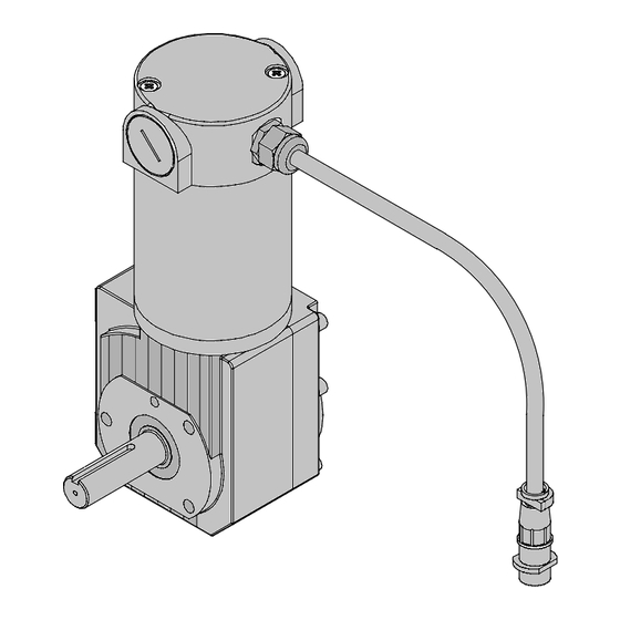
SECTION 3 − INSTALLATION 3-1. Specifications Rated Model Volts Horsepower Motor Speed Ratio Rated Torque Output Speed RAD−100 115 VDC 1/5 HP 2500 RPM 120 : 1 290 in. lb 21 RPM 3-2. Description Motor This unit is a heavy-duty motor de- signed for automated strip clad ap- plications. -
Page 16: Overall Dimensions And Mounting Hole Layout
3-3. Overall Dimensions And Mounting Hole Layout Inches Millimeters 4.425 5.325 11.000 4.425 in. 1.656 in. 1/4 in.−20 UNC 2B THRD .500 in. Deep 11.000 in. 2.896 in. Bolt Circle Section B-B Scale 1:1 5/16 in.−18 UNC 2B THRD .188 in. .500 in. -
Page 17: Plug Connections
3-4. Plug Connections Weld Control Motor Control Cord (Part Number 212591 Not Supplied) Motor To make connections, align key- way, insert plug, and tighten threaded collar. 805 216-A 3-5. Remote 10 Receptacle RC2 Information (For Part Number 212591) Socket Socket Information REMOTE 10 To positive (+) motor armature (115 volts DC motor). -
Page 18: Section 4 − Maintenance And Troubleshooting
SECTION 4 − MAINTENANCE AND TROUBLESHOOTING 4-1. Routine Maintenance Disconnect power before maintaining. 3 Months Clean Repair Or Replace Replace Unreadable Tighten Cracked Labels Weld Weld Terminals Cable Replace Cord Cracked Hose Cable Parts 6 Months Blow Out Or Clean Vacuum Inside. -
Page 19: Brush Inspection And Replacement
4-2. Brush Inspection And Replacement Brush Cap Spring Clip Brush Remove brush cap. Remove spring 3/8 in (9.5 mm) clip and brush. Minimum Length Replace brush if it becomes chipped or broken, or if less than 3/8 in (9.5 3/4 in (19 mm) mm) of brush material is left. -
Page 20: Section 5 − Electrical Diagram
SECTION 5 − ELECTRICAL DIAGRAM PLG1 GREEN Motor BROWN PLG1 BARE GREEN BLACK TACH WHITE Figure 5-1. Circuit Diagram OM-238 428 Page 16... - Page 21 Notes MATERIAL THICKNESS REFERENCE CHART 24 Gauge (.025 in) 22 Gauge (.031 in) 20 Gauge (.037 in) 18 Gauge (.050 in) 16 Gauge (.063 in) 14 Gauge (.078 in) 1/8 in (.125 in) 3/16 in (.188 in) 1/4 in (.25 in) 5/16 in (.313 in) 3/8 in (.375 in) 1/2 in (.5 in)
-
Page 22: Section 6 − Parts List
SECTION 6 − PARTS LIST Hardware is common and not available unless listed. 805 217-A Figure 6-1. Motor Assembly Item Dia. Part Mkgs. Description Quantity Figure 6-1. Motor Assembly ... . 238 429 . - Page 23 Effective January 1, 2008 (Equipment with a serial number preface of LJ or newer) This limited warranty supersedes all previous Miller warranties and is exclusive with no other Warranty Questions? guarantees or warranties expressed or implied. LIMITED WARRANTY − Subject to the terms and conditions...
- Page 24 Contact the Delivering Carrier to: File a claim for loss or damage during shipment. For assistance in filing or settling claims, contact your distributor and/or equipment manufacturer’s Transportation Department. © PRINTED IN USA 2008 Miller Electric Mfg. Co. 2008−01...
Need help?
Do you have a question about the RAD-100 and is the answer not in the manual?
Questions and answers