Table of Contents
Advertisement
Quick Links
XX181-03-00
VN-855V4 AND VN-855V4-C
VN-855DNV4 AND VN-855DNV4-C
VN-855WDRV4 AND VN-855WDRV4-C
IP CAMERAS
Vicon Industries Inc. does not warrant that the functions contained in this equipment will meet your
requirements or that the operation will be entirely error free or perform precisely as described in the
documentation. This system has not been designed to be used in life-critical situations and must not
be used for this purpose.
Warning: To prevent fire or shock hazard, do not expose the unit to rain
or moisture.
Copyright © 2007 Vicon Industries Inc. All rights reserved.
Product specifications subject to change without notice.
Vicon and its logo are registered trademarks of Vicon Industries Inc.
ViconNet, Kollector and their logos are registered trademarks of Vicon Industries Inc.
I-Onyx and its logo is a trademark of Vicon Industries Inc.
VICON INDUSTRIES INC., 89 ARKAY DRIVE, HAUPPAUGE, NY 11788
TEL: 631-952-CCTV (2288) FAX: 631-951-CCTV (2288)
TOLL FREE: 800-645-9116
24-Hour Technical Support: 800-34-VICON (800-348-4266)
UK: 44 (0) 1489-566300
WEB: www.vicon-cctv.com
Vicon part number 8009-8181-03-00
Rev 1107
Section 1/3
Advertisement
Table of Contents

Related Manuals for i-onyx VN-855V4 AND

Summary of Contents for i-onyx VN-855V4 AND
- Page 1 Vicon and its logo are registered trademarks of Vicon Industries Inc. ViconNet, Kollector and their logos are registered trademarks of Vicon Industries Inc. I-Onyx and its logo is a trademark of Vicon Industries Inc. VICON INDUSTRIES INC., 89 ARKAY DRIVE, HAUPPAUGE, NY 11788...
- Page 3 FCC Notice Note: Complies with Federal Communications Commission Rules & Regulations Part 15, Subpart B for a Class A digital device. WARNING This equipment generates and uses radio frequency energy and if not installed and used properly, that is, in strict accordance with the manufacturer’s instruction, may cause interference to radio and television reception.
-
Page 5: Table Of Contents
Contents Important Safeguards ............................i Precautions ............................... 2 Connectors and Controls ..........................3 OSD Menu for VN-855WDR..........................8 ViconNet Configuration..........................15 Shipping Instructions............................ 25 Coaxial Cable Recommendations........................ 26 Twisted-Pair Cable ............................27 Network Cable..............................28 Technical Information ........................... 29 Vicon Standard Equipment Warranty...................... -
Page 7: Important Safeguards
Important Safeguards 12. Power Cord Protection - Power supply cords should not GRAPHIC SYMBOL EXPLANATION be routed in trafficked areas or in tight spaces where they will be pinched or used to bear weight. Allow some slack in the The lightening bolt symbol alerts the user to the presence of cord where it enters the unit. -
Page 8: Precautions
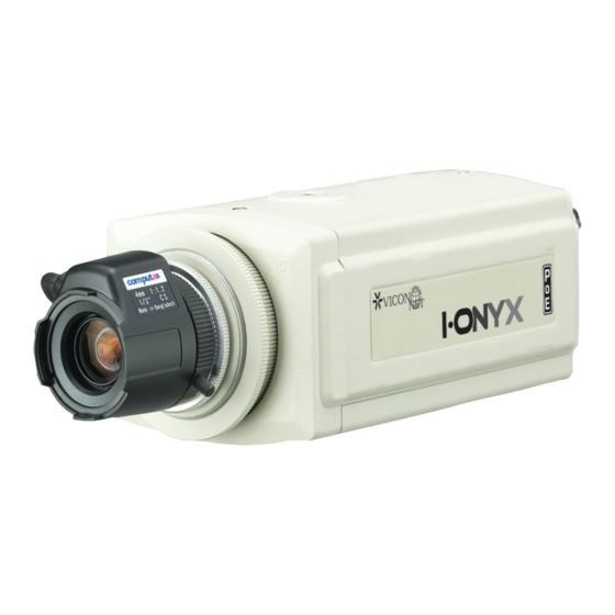
4. Power connector – 1 pc 5. 6-pin alarm/mic connector – 1 pc The I-Onyx™ VN-855 is an integrated camera that captures digital video as well as converts analog video ® to digital video and transmits the video over the ViconNet network (using Version 4 software). -
Page 9: Connectors And Controls
CONNECTORS AND CONTROLS [High-Resolution Model VN-855] [Day/Night Model VN-855DN] [WDR Model VN-855WDR] XX181-03-00 Rev 1107 VN-855V4 IP Camera... - Page 10 1. ETHERNET (Network Port) Connects to Internet, Ethernet (10Base-T/100Base-T). There are 2 LEDs on the RJ-45 connector. The green LED indicates that there is connection to the Network. The amber LED indicates Network activity (data flowing to the camera). This connection also provides PoE (Power over Ethernet). When using PoE, a PoE device, such as the NETSWITCHPOE-24, is required.
- Page 11 mode selected, a fixed or manual iris lens can be used instead of an autoiris lens. In the AI/ALC mode, the CCD shutter speed is fixed to 1/60 (NTSC, 1/50 PAL) sec, and the incoming light level is controlled by the autoiris lens. When using a DC-drive type of autoiris lens, set this switch to the AI/ALC position.
- Page 12 WITH BLC/WDR OFF WITH BLC ON WITH WDR ON 4. AGC (Automatic gain Control) ON/OFF This switch is provided for the AGC circuit. The AGC circuit incorporated into the camera boosts the sensitivity automatically when the scene illumination is insufficient. 5.
- Page 13 7. ALC LEVEL ADJUSTMENT POTENTIOMETER FOR DC DRIVE LENS This potentiometer is used only if the camera is fitted with a DC drive autoiris lens. It is used to control the amount of light striking the CCD image sensor. LENS-IRIS level control Monitor Screen LEVEL Control Direction To increase the brightness...
-
Page 14: Osd Menu For Vn-855Wdr
3. Open the iris completely. If an autoiris lens used, reduce the room lighting to allow the lens to open completely. This gives the most accurate results. 4. Zoom the lens in to the maximum telephoto setting. Adjust the optical focus of the lens using the remote lens control. - Page 15 Menu Flow Chart MANUAL LENS ELC level setting (MANUAL/DC) BLC level and zone setting (OFF/BLC/WDR) WDR level setting DAY/NIGHT COLOR SHUTTER SPEED, AGC, FLICKERLESS setting (COLOR/BW SHUTTER SPEED, AGC, FLICKERLESS setting MANUAL MANUAL RED, BLUE value setting (ATW1/ATW2/AWC/MANUAL) SPECIAL BLEMISH, PRIORITY, POSI/NEGA, SHARPNESS EXIT (QUIT/SAVE/PRESET) Main Menu...
- Page 16 LENS Select according to lens type: Manual Iris Lens: Manual mode DC Drive Lens: DC mode When WDR function is set to ON, mode changes to DC mode, and DC Iris level cannot be setup. DC Drive Lens In Lens menu, select DC using Tilt Up/Down and press AP key. When in DC mode, settings are done using to Level control potentiometer on the camera.
- Page 17 With BLC function, the face displays clearly. In the WDR Menu: Select BLC and press AP key. In the screen that follows, select “Level” and “Area” (Right, Left, Top, Bottom). (WDR) LENS MANUAL4 DAY/NIGHT COLOR4 ATW1 SPECIAL EXIT QUIT LEVEL AREA RIGHT Use ▲...
- Page 18 Black-and-White (BW) In this mode, video output is black-and-white (without IR filter), regardless of illumination. This function is useful in a dark environment and is the same as using a black-and-white camera. Day/Night Menu: Select BW and enter Preset 94. In the screen that follows, select Shutter (speed), AGC (Level), and Flickerless (ON/OFF).
- Page 19 This function is used to set the best color temperature in the current environment. If camera has full white screen in front of white paper, and AP key is pressed, the camera is fixed at the best color temperature. “Wait” displays while it sets. When the environment is changed, new settings are needed using the same method.
- Page 20 SPECIAL In Special menu, if AP key is pressed, Blemish, Priority, Posi/Nega, and Sharpness can be adjusted. (SPECIAL) LENS MANUAL4 BLEMISH DAY/NIGHT COLOR4 PRIORITY DIP SW POSI/NEGA SPECIAL SHARPNESS EXIT QUIT Use AI to exit Use ▲ ▼ ◀ ▶ , AP to select Blemish Blemish Mode is selectable between ON and OFF using Pan Left/Right.
-
Page 21: Viconnet Configuration
EXIT Exit Menu is used to close the menu. The menu is setup with 3 choices (Quit, Save, Preset). LENS MANUAL4 DAY/NIGHT COLOR4 ATW1 SPECIAL EXIT QUIT Use the AP key to exit the OSD system. QUIT Changes are not saved. Previously saved menu remains and the menu is closed SAVE Changes are saved and menu is closed. - Page 22 Configuring ViconNet (IP/LAN) The VN-855 IP Camera is shipped with a ViconNet Version 4 CD that contains the ViconNet Version 4 software needed to setup your IP system, including the application setup, the camera firmware and setup software (VNSetup). Be sure the ViconNet Workstation meets the minimum requirements, is running the ViconNet application (version 4) (VNSetup) and has the proper PTZ camera driver.
- Page 23 IMPORTANT NOTE! XX181-03-00 Rev 1107 VN-855V4 IP Camera...
- Page 24 Configuring the Network Settings Note: Before starting, make sure that VNSetup is installed on the configuring PC\workstation. Installation is done using the CD included. There are two ways to change the IP camera network settings: • Activating the camera for the first time: via VNSetup application. •...
- Page 25 Select TAB The Select TAB allows the user to select the relevant IP Unit in order to change its settings or to upgrade its version. 1. From the Unit selection list, select the relevant IP product. In case of multiple sites, it is advised to use the filter under the Unit Type field.
- Page 26 Select Unit TAB The Unit TAB allows the user to change the following settings: Unit name, Nucleus IP address, IP address, Net mask, Gateway, DNS, DHCP, Time Zone, daylight saving time, Local time, Local date, and Debug level, on a scale of 0-4, where 4 is most information. Note: The Apply button must be pressed for changes to take effect.
- Page 27 Install TAB The Install TAB allows the user to install/upgrade newer versions. Install Info Tab The Info TAB displays the selected IP product general information/ Info Advanced TAB The Advanced TAB functionalities allow the user to handle unexpected events on a specific remote unit when they occur.
- Page 28 The Main app starting mode, Application start status may be Unknown, Application loaded successfully or Loading of application is disabled. The Disable load button allows the pausing of the application load in case of software issues while still permitting communication via VNSetup; the Enable load button resumes the application load.
- Page 29 ViconNet Configuration After the camera has been setup with the proper IP address, configuration features from a remote workstation, server or recorder are available as follows. • A network settings screen is used to modify the camera’s IP parameters. This allows great flexibility in network setup.
- Page 30 ViconNet (IP/LAN) Version Operation The following functions are supported by the ViconNet system through a workstation, recorder or server. 1. System macros can be configured to view and record the camera’s video. In addition, within macros, alarms can be sent and remote macros triggered. 2.
-
Page 31: Shipping Instructions
Shipping Instructions Use the following procedure when returning a unit to the factory: 1. Call or write Vicon for a Return Authorization (R.A.) at one of the locations listed below. Record the name of the Vicon employee who issued the R.A. Vicon Industries Inc. -
Page 32: Coaxial Cable Recommendations
Coaxial Cable Recommendations Caution: Careful selection of proper cable is essential to obtain the best performance from this equipment. Vicon assumes no responsibility for poor performance when cables other than those recommended, or equivalent, are installed. In all cases, coaxial cable impedance should be 75 ohms. Materials Use only a pure copper center conductor. -
Page 33: Twisted-Pair Cable
Twisted-Pair Cable Caution: Careful selection of proper cable is essential to obtain the best performance. Vicon assumes no responsibility for poor performance when cables other than the recommended types, or equivalent, are used. Materials Use a pure copper stranded conductor with or without a tin-plating to obtain a low DC resistance. Do not use cable with either steel or aluminum stranded conductor because they do not transfer signals effectively for long distances. -
Page 34: Network Cable
Network Cable Caution: Careful selection of proper cable is essential to obtain the best performance. Vicon assumes no responsibility for poor performance when cables other than the recommended types, or equivalent, are used. Materials Use pure copper stranded conductors to obtain a low DC resistance. The preferred insulation and cable jacket is Polyvinyl chloride (PVC). -
Page 35: Technical Information
Technical Information ELECTRICAL SOFTWARE OPERATION Input Power Source: 24 VAC, ±15% or PoE (802.3af Network Setup: Standard network protocol type compatible). using IP addressing scheme and separate application Input software. Power Isolation: Internal fully isolated power input. Site Authorization: Camera can be setup using remote recorder or workstation Current: VN-855: 360 mA max. - Page 36 MECHANICAL Signal-to-Noise Dimensions: See Figure. Ratio: Better than 52 dB. Height (H): 2.2 in. (56 mm). Width (W): 2.9 in. (74 mm). White Balance: Automatic. Distance from Base Length (L): 5.3 in. (135 mm). to Optical Center Video Signal Output: 1.0 V p-p VBS @ 75 ohms of Lens (X): 1.1 in.
-
Page 37: Vicon Standard Equipment Warranty
Vicon Standard Equipment Warranty Vicon Industries Inc. (the “Company”) warrants your equipment to be free from defects in material and workmanship under Normal Use from the date of original retail purchase for a period of three years, with the following exceptions: VCRs, all models: Labor and video heads warranted for 120 days from date of original retail purchase. - Page 38 Vicon Industries Inc. Corporate Headquarters 89 Arkay Drive Hauppauge, New York 11788 631-952-CCTV (2288) 800-645-9116 Fax: 631-951-CCTV (2288) Vicon Europe Headquarters Brunel Way Fareham, PO15 5TX United Kingdom +44 (0) 1489 566300 Fax: +44 (0) 1489 566322 Germany vin-videotronic infosystems gmbh Lahnstrasse 1 D-24539 Neumuenster Phone: +49 (0) 4321 8790...
Need help?
Do you have a question about the VN-855V4 AND and is the answer not in the manual?
Questions and answers