
Related Manuals for Velleman WST8089


Summary of Contents for Velleman WST8089
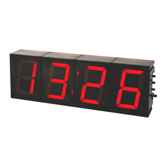
- Page 1 57mm 7-SEGMENT DIGITAL CLOCK Total solder points: 263 Difficulty level: beginner 1 2 3 4 5 advanced K8089 K8089 ILLUSTRATED ASSEMBLY MANUAL H8089IP-1...
- Page 2 VELLEMAN NV Legen Heirweg 33 9890 Gavere Belgium Europe www.velleman.be www.velleman-kit.com...
- Page 3 Features & specifications Features : 12/24h clock system min temp readout: • celsius: -20°C • fahrenheit: -4°F max temp readout: • celsius: 70°C • fahrenheit: 158°F auto toggle function easy time setting easy wall mounting ...
- Page 4 Assembly hints 1. Assembly (Skipping this can lead to troubles ! ) Ok, so we have your attention. These hints will help you to make this project successful. Read them carefully. 1.1 Make sure you have the right tools: A good quality soldering iron (25-40W) with a small tip. •...
- Page 5 REMOVE THEM FROM THE TAPE ONE AT A TIME ! DO NOT BLINDLY FOLLOW THE ORDER OF THE COMPONENTS ONTO THE TAPE. ALWAYS CHECK THEIR VALUE ON THE PARTS LIST!
- Page 6 Construction Hint: if you want the mount the clock against a wall, you can use the unstuffed PCB as a template to mark the drill holes. 1. Resistors. 3. Zener diodes (check the polarity) ZD... ZD1 : 4V3 R... ...
- Page 7 Construction 7. Transistors 12. Terminal blocks T1 : BC547 SK1 : 2p power 12VAC T2 : BC547 SK2 : 3p Temp. sensor ! If remote selection is needed : 8. Voltage regulator SW1 : 2p Open/closed ...
-
Page 8: Solder Side
Construction MOUNT THESE COMPONENTS ON THE PCB SOLDERSIDE, SOLDER THEM ON THE COMPONENTS SIDE 1. Tulip pin headers DY1 : 2 x 5pins DY2 : 2 x 5pins DY3 : 2 x 5pins DY4 : 2 x 5pins SOLDER SIDE... - Page 9 construction 2. Digit displays DY1 ATTENTION: mount the displays so that the DY2 dot is mounted towards the push button. DY3 DY4 Side with push buttons Make sure that all displays are correctly mounted ! 3. Assembly of the enclosure Mount the leds, watch the polarity.
- Page 10 Construction 4. Test and connection 1. Power supply: Supply 9-12VAC to the inputs marked '12VAC'. Make sure supply can deliver 300mA Make sure to use an AC power supply. If you supply a DC voltage, the accuracy of the clock will be 5% worst case. 2.
- Page 11 Optional sensor K8067/VM132 K8089 Adjusting the temperature sensor (Skip this if there is no temp. sensor connected. In this case, make sure jumper is set to 'clock'). Put a reliable thermometer next to the temperature sensor and leave it there for a while.
- Page 12 Jumper setting jumper, to select how seconds are indicated. hh.mm hh:mm hh mm 7. Assembly in enclosure Assemble the 4 individual housing together. Turn the PCB around with the displays on top, place the enclosure on the PCB.
- Page 13 8. Use Minute 'Min' Hour ' Hrs' Mode Message select 1. Use as thermometer only (no clock): Hold 'Min'-button and apply power. Unit will display tem- perature only. If required, you can permanently bridge the 'Min'-button. 2. Setting the time: Select 12h or 24h readout by means of the jumper.
- Page 16 Enter the world of microcontroller programming, easy step by step instructions. Includes programmer and test board. Modifications and typographical errors reserved © Velleman Kit nv H8089IP - 2009 (rev.3) 5 4 1 0 3 2 9 4 0 3 1 8 8...
Need help?
Do you have a question about the WST8089 and is the answer not in the manual?
Questions and answers