Table of Contents
Advertisement
Quick Links
FCC Information and Copyright
This equipment has been tested and found to comply with the limits of a Class
B digital device, pursuant to Part 15 of the FCC Rules. These limits are designed
to provide reasonable protection against harmful interference in a residential
installation. This equipment generates, uses, and can radiate radio frequency
energy and, if not installed and used in accordance with the instructions, may
cause harmful interference to radio communications. There is no guarantee
that interference will not occur in a particular installation.
The vendor makes no representations or warranties with respect to the
contents here and specially disclaims any implied warranties of merchantability
or fitness for any purpose. Further the vendor reserves the right to revise this
publication and to make changes to the contents here without obligation to
notify any party beforehand.
Duplication of this publication, in part or in whole, is not allowed without first
obtaining the vendor's approval in writing.
The content of this user's manual is subject to be changed without notice and
we will not be responsible for any mistakes found in this user's manual. All the
brand and product names are trademarks of their respective companies.
A57A Setup Manual
Dichiarazione di conformità
sintetica
Ai sensi dell'art. 2 comma 3 del D.M.
275 del 30/10/2002
Si dichiara che questo prodotto è
conforme alle normative vigenti e
soddisfa i requisiti essenziali richiesti
dalle direttive
2004/108/CE, 2006/95/CE e
1999/05/CE
quando ad esso applicabili
Short Declaration of conformity
We declare this product is complying
with the laws in force and meeting all
the essential requirements as specified
by the directives
2004/108/CE, 2006/95/CE and
1999/05/CE
whenever these laws may be applied
Advertisement
Table of Contents

Related Manuals for Biostar A57A


Summary of Contents for Biostar A57A
- Page 1 A57A Setup Manual FCC Information and Copyright This equipment has been tested and found to comply with the limits of a Class B digital device, pursuant to Part 15 of the FCC Rules. These limits are designed to provide reasonable protection against harmful interference in a residential installation.
-
Page 2: Table Of Contents
Software....................21 Extra Information................23 AMI BIOS Beep Code................24 Troubleshooting...................25 Chapter 6: bios update ............... 26 BIOS Update Utility ................26 Online Update Utility ................28 BIOSTAR BIOS Flasher .................30 Appendix: SPEC In Other Languages..........32 German ........................32 French........................34 Italian........................36 Spanish ........................38 Portuguese .......................40 Polish........................42... -
Page 3: Chapter 1: Introduction
A57A CHAPTER 1: INTRODUCTION EFORE TART Thank you for choosing our product. Before you start installing the motherboard, please make sure you follow the instructions below: Prepare a dry and stable working environment with sufficient lighting. Always disconnect the computer from power outlet before operation. -
Page 4: Motherboard Features
Motherboard Manual OTHERBOARD EATURES SPEC Socket FM1 AMD 64 Architecture enables 32 and 64 bit AMD A-Series / E2-Series processors computing Chipset AMD A55 ITE 8728 Environment Control initiatives Provides the most commonly used legacy H/W Monitor Super I/O Super I/O functionality Fan Speed Controller Low Pin Count Interface ITE's "Smart Guardian"... -
Page 5: Rear Panel Connectors
Audio Jack Provide Audio-In/Out and Mic. connection Board Size 200 mm (W) x 295 mm (L) Biostar reserves the right to add or remove support OS Support Windows XP / Vista / 7 for any OS With or without notice. -
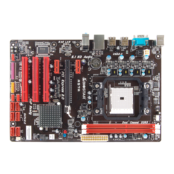
Page 6: Motherboard Layout
Motherboard Manual OTHERBOARD AYOUT KBMS1 CPU_FAN1 ATXPWR2 USB1 USB2 ATXPWR1 RJ45USB1 BAT1 AUDIO1 PEX1_1 PEX16_1 PEX1_2 PCI1 Super BIOS PCI2 JCMOS1 PCI3 SATA2 SATA4 SATA6 Codec SATA1 SATA3 SATA5 JSPDIFOUT1 F_USB1 J_PRINT1 PANEL1 F_USB2 F_AUDIO1 Note: represents the 1 pin. ■... -
Page 7: Chapter 2: Hardware Installation
A57A CHAPTER 2: HARDWARE INSTALLATION (CPU) NSTALLING ENTRAL ROCESSING Step 1: Pull the lever toward direction A from the socket and then raise the lever up to a 90-degree angle. Step 2: Look for the white triangle on socket, and the gold triangle on CPU should point towards this white triangle. - Page 8 Motherboard Manual Step 3: Hold the CPU down firmly, and then close the lever toward direct B to complete the installation. Step 4: Put the CPU Fan on the CPU and buckle it. Connect the CPU FAN power cable to the CPU_FAN1. This completes the installation.
-
Page 9: Fan Headers
A57A FAN H EADERS These fan headers support cooling-fans built in the computer. The fan cable and connector may be different according to the fan manufacturer. Connect the fan cable to the connector while matching the black wire to pin#1. -
Page 10: Installing System Memory
Motherboard Manual NSTALLING YSTEM EMORY A. DDR3 Modules Unlock a DIMM slot by pressing the retaining clips outward. Align a DIMM on the slot such that the notch on the DIMM matches the break on the Slot. Insert the DIMM vertically and firmly into the slot until the retaining chip snap back in place and the DIMM is properly seated. - Page 11 A57A B. Memory Capacity DIMM Socket Total Memory DDR3 Module Location Size DDR3_A1 512MB/1GB/2GB/4GB/8GB Max is 16GB. DDR3_B1 512MB/1GB/2GB/4GB/8GB C. Dual Channel Memory installation Please refer to the following requirements to activate Dual Channel function: Install memory module of the same density in pairs, shown in the table...
-
Page 12: Connectors And Slots
Motherboard Manual ONNECTORS AND LOTS SATA1~SATA6: Serial ATA Connectors The motherboard has a PCI to SATA Controller with 6 channels SATA interface, it satisfies the SATA 2.0 spec and with transfer rate of 3.0Gb/s. Assignment Ground Ground S A TA 2 S A TA S A T A S A TA... - Page 13 A57A ATXPWR1: ATX Power Source Connector This connector allows user to connect 24-pin power connector on the ATX power supply. Assignment Assignment +3.3V +3.3V -12V +3.3V Ground Ground PS_ON Ground Ground Ground Ground Ground PW_OK Standby Voltage+5V +12V +12V Ground +3.3V...
- Page 14 Motherboard Manual PEX16_1: PCI-Express Gen2 x16 Slot PCI-Express 2.0 compliant. Maximum theoretical realized bandwidth of 8GB/s simultaneously per direction, for an aggregate of 16GB/s totally. PCI-Express Gen2 supports a raw bit-rate of 5.0Gb/s on the data pins. 2X bandwidth over the PCI-Express 1.1 architecture. PEX1_1/PEX1_2: PCI-Express Gen2 x1 Slots PCI-Express 2.0 compliant.
-
Page 15: Chapter 3: Headers & Jumpers Setup
A57A CHAPTER 3: HEADERS & JUMPERS SETUP OW TO ETUP UMPERS The illustration shows how to set up jumpers. When the jumper cap is placed on pins, the jumper is “close”, if not, that means the jumper is “open”. Pin opened... - Page 16 Motherboard Manual JCMOS1: Clear CMOS Header Placing the jumper on pin2-3 allows user to restore the BIOS safe setting and the CMOS data. Please carefully follow the procedures to avoid damaging the motherboard. Pin 1-2 Close: Normal Operation (default). Pin 2-3 Close: Clear CMOS data.
- Page 17 A57A F_AUDIO1: Front Panel Audio Header This header allows user to connect the front audio output cable with the PC front panel. This header supports HD and AC’97 audio front panel connector. HD Audio AC’97 Assignment Assignment Mic Left in...
- Page 18 Motherboard Manual J_PRINT1: Printer Port Connector This header allows you to connector printer on the PC. Assignment Assignment -Strobe Ground -ALF Data 6 Data 0 Ground -Error Data 7 Data 1 Ground -Init -ACK Data 2 Ground -Scltin Busy Data 3 Ground Ground Data 4...
-
Page 19: Chapter 4: Raid Functions
A57A CHAPTER 4: RAID FUNCTIONS PERATING YSTEM Supports Windows Vista and Windows 7. RRAYS RAID supports the following types of RAID arrays: RAID 0: RAID 0 defines a disk striping scheme that improves disk read and write times for many applications. - Page 20 Motherboard Manual RAID 1: Every read and write is actually carried out in parallel across 2 disk drives in a RAID 1 array system. The mirrored (backup) copy of the data can reside on the same disk or on a second redundant drive in the array.
- Page 21 A57A RAID 10: RAID 1 drives can be stripped using RAID 0 techniques. Resulting in a RAID 10 solution for improved resiliency, performance and rebuild performance. Features and Benefits Drives: Minimum 4, and maximum is 6 or 8, depending on the platform.
-
Page 22: Chapter 5: Useful Help
Motherboard Manual CHAPTER 5: USEFUL HELP RIVER NSTALLATION After you installed your operating system, please insert the Fully Setup Driver CD into your optical drive and install the driver for better system performance. You will see the following window after you insert the CD The setup guide will auto detect your motherboard and operating system. -
Page 23: Software
A57A OFTWARE Installing Software 1. Insert the Setup CD to the optical drive. The drivers installation program would appear if the Autorun function has been enabled. 2. Select Software Installation, and then click on the respective software title. 3. Follow the on-screen instructions to complete the installation. - Page 24 If you are not using Outlook Express as your default e-mail client application, you may need to save the system information to a .txt file and send the file to our tech support with other e-mail application. Go to the following web http://www.biostar.com.tw/app/en/about/contact.php for getting our contact information.
-
Page 25: Extra Information
A57A BIOS Update Utility BIOS Update Utility is a convenient utility which allows you to update your motherboard BIOS under Windows system. Please refer to the detailed instructions in the section 6.1 BIOS Update Utility of Chapter 6. XTRA NFORMATION... -
Page 26: Ami Bios Beep Code
Motherboard Manual AMI BIOS B Boot Block Beep Codes Number of Beeps Description No media present. (Insert diskette in floppy drive A:) “AMIBOOT.ROM” file not found in root directory of diskette in Insert next diskette if multiple diskettes are used for recovery Flash Programming successful File read error No Flash EPROM detected... -
Page 27: Troubleshooting
A57A ROUBLESHOOTING Probable Solution There is no power in the system. Make sure power cable is Power LED does not shine; the securely plugged in. fan of the power supply does not Replace cable. work Contact technical support. Indicator light on keyboard does not shine. -
Page 28: Chapter 6: Bios Update
CHAPTER 6: BIOS UPDATE There are three ways to update the BIOS: BIOS Update Utility, BIOS Online Update Utility and BIOSTAR BIOS Flasher. Note: The programing procedure may take minutes, please do not make any operation during the programing process. - Page 29 A57A 6. After the BIOS Update process is finished, click on OK to reboot the system. 7. While the system boots up and the full screen logo shows up, please press the <Delete> key to enter BIOS setup. After entering the BIOS setup, please go to the Save & Exit, using the Restore Defaults function to load Optimized Defaults, and select Save Changes and Reset to restart the computer.
-
Page 30: Online Update Utility
Motherboard Manual NLINE PDATE TILITY 1. Installing BIOS Update Utility from the CD Driver. 2. Please make sure the system is connected to the internet before using this function. 3. Open BIOS Update Utility and click the Online Update button on the main screen. 4. - Page 31 A57A 7. After the updating process is finished, you will be asked you to reboot the system. Click OK to reboot. 8. While the system boots up and the full screen logo shows up, press <Delete> key to enter BIOS setup.
-
Page 32: Biostar Bios Flasher
BIOSTAR BIOS Flasher is a BIOS flashing utility providing you an easy and simple way to update your BIOS via USB pen drive. The BIOSTAR BIOS Flasher is built in the BIOS ROM. To enter the utility, press <F12> during the Power-On Self Tests (POST) procedure while booting up. - Page 33 A57A 6. Select the proper BIOS file, and a message asking if you are sure to flash the BIOS file. Click Yes to start updating BIOS. 7. A dialog pops out after BIOS flash is completed, asking you to restart the system.
-
Page 34: Appendix: Spec In Other Languages
Motherboard Manual APPENDIX: SPEC IN OTHER LANGUAGES ERMAN Spezifikationen Sockel FM1 Die AMD 64-Architektur unterstützt eine 32-Bit- und AMD A-Series / E2-Series Prozessoren 64-Bit-Datenverarbeitung Chipsatz AMD A55 ITE 8728 Umgebungskontrolle, Bietet die häufig verwendeten alten Super Hardware-Überwachung Super E/A E/A-Funktionen. Lüfterdrehzahl-Controller Low Pin Count-Schnittstelle "Smart Guardian"-Funktion von ITE... - Page 35 Rückseiten-E Serieller Anschluss LAN-Anschluss USB2.0-Anschluss Audioanschluss Platinengröße 200 mm (B) X 295 mm (L) Biostar behält sich das Recht vor , ohne Ankündigung OS-Unterstüt Windows XP / Vista / 7 die Unterstützung für ein Betriebssystem zung hinzuzufügen oder zu entfernen.
-
Page 36: French
Motherboard Manual RENCH SPEC Socket FM1 L'architecture AMD 64 permet le calcul 32 et 64 bits Processeurs AMD A-Series / E2-Series Chipset AMD A55 ITE 8728 Initiatives de contrôle environnementales, Fournit la fonctionnalité de Super E/S Moniteur de matériel Super E/S patrimoniales la plus utilisée. - Page 37 Port USB2.0 Fiche audio Dimensions 200 mm (l) X 295 mm (H) de la carte Biostar se réserve le droit d'ajouter ou de supprimer le Support SE Windows XP / Vista / 7 support de SE avec ou sans préavis.
-
Page 38: Italian
Motherboard Manual TALIAN SPECIFICA Socket FM1 L’architettura AMD 64 abilita la co mputazione 32 Processori AMD A-Series / E2-Series e 64 bit Chipset AMD A55 ITE 8728 Funzioni di controllo dell’ambiente: Fornisce le funzionalità legacy Super Monitoraggio hardware Super I/O I/O usate più... - Page 39 Porta USB2.0 Connettore audio Dimension 200 mm (larghezza) x 295 mm i scheda (altezza) Biostar si riserva il diritto di aggiungere o Sistemi operativi Windows XP / Vista / 7 rimuovere il supporto di qualsiasi sistema supportati operativo senza preavviso.
-
Page 40: Spanish
Motherboard Manual PANISH Especificación Conector FM1 La arquitectura AMD 64 permite el procesado de 32 y Procesadores AMD A-Series / E2-Series 64 bits Conjunto de AMD A55 chips ITE 8728 Iniciativas de control de entorno, Le ofrece las funcionalidades heredadas de Monitor hardware Súper E/S uso más común Súper E/S. - Page 41 Tamaño de 200 mm. (A) X 295 mm. (H) la placa Soporte de Biostar se reserva el derecho de añadir o retirar el sistema Windows XP / Vista / 7 soporte de cualquier SO con o sin aviso previo. operativo...
-
Page 42: Portuguese
Motherboard Manual ORTUGUESE ESPECIFICAÇÕES Socket FM1 A arquitectura AMD 64 permite uma computação de 32 Processadores AMD A-Series / E2-Series e 64 bits Chipset AMD A55 ITE 8728 Iniciativas para controlo do ambiente Proporciona as funcionalidades mais Especificaçã Monitorização do hardware utilizadas em termos da especificação o Super I/O Controlador da velocidade da ventoinha... - Page 43 Porta USB2.0 Tomada de áudio Tamanho 200 mm (L) X 295 mm (A) da placa A Biostar reserva-se o direito de adicionar ou remover Sistemas operativos Windows XP / Vista / 7 suporte para qualquer sistema operativo com ou sem suportados aviso prévio.
-
Page 44: Polish
Motherboard Manual OLISH SPEC Socket FM1 Architektura AMD 64 umożliwia przetwarzanie 32 i 64 Procesor AMD A-Series / E2-Series Procesory bitowe Chipset AMD A55 Gniazda DDR3 DIMM x 2 Moduł pamięci DDR3 z trybem podwójnego kanału Pamięć Maks. wielkość pamięci 16GB Obsługa DDR3 800/1066/1333/1600/1866 główna Każde gniazdo DIMM obsługuje moduły... - Page 45 Back Panel Port szeregowy Port LAN Port USB2.0 Gniazdo audio Wymiary 200 mm (S) X 295 mm (W) płyty Obsluga Biostar zastrzega sobie prawo dodawania lub systemu Windows XP / Vista / 7 odwoływania obsługi dowolnego systemu operacyjne operacyjnego bez powiadomienia.
-
Page 46: Russian
Motherboard Manual USSIAN СПЕЦ (центральн Гнездо FM1 Архитектура AMD 64 разрешать обработка ый Процессоры AMD A-Series / E2-Series данных на 32 и 64 бит процессор) Набор AMD A55 микросхем Модуль памяти с двухканальным режимом DDR3 Слоты DDR3 DIMM x 2 Поддержка... - Page 47 средств ввода-выв Порт LAN ода USB2.0-порт наушников Размер 200 мм (Ш) X 295 мм (В) панели Biostar сохраняет за собой право добавлять или Поддержка Windows XP / Vista / 7 удалять средства обеспечения для OS с или без предварительного уведомления.
-
Page 48: Arabic
Motherboard Manual RABIC اﻟﻤﻮاﺻﻔﺎت ﻡﻘﺒﺲFM1 وﺣﺪة اﻟﻤﻌﺎﻟﺠﺔ ﺗﻤﻜﻦ ﺗﻘﻨﻴﺔAMD 64 ﺏﺖ و إﺝﺮاء اﻟﻌﻤﻠﻴﺎت اﻟﺤﺎﺳﻮﺏﻴﺔ ﺏﺴﺮﻋﺔ اﻟﻤﺮآﺰﻳﺔ ﻡﻌﺎﻟﺠﺎتAMD A-Series / E2-Series ﻡﺠﻤﻮﻋﺔ اﻟﺸﺮاﺋﺢ AMD A55 وﺣﺪة ذاآﺮةDDR3 ﻡﺰدوﺝﺔ اﻟﻘ ﻨﺎة ﻋﺪد DDR3 DIMM ﻓﺘﺤﺔ 1866 1600 1333 1066 ﺗﺪﻋﻢ اﻟﺬاآﺮة ﻡﻦ ﻥﻮعDDR3 ﺳﻌﺎت... - Page 49 اﻟﻠﻮﺣﺔ اﻟﺨﻠﻔﻴﺔ ﻋﺪد ﻡﻨﻔﺬ ﺵﺒﻜﺔ اﺗﺼﺎل ﻡﺤﻠﻴﺔ ﻋﺪد ﻡﻨﺎﻓﺬ ﻋﺪد ﻡﻘﺒﺲ ﺹﻮت ارﺗﻔﺎع ﻡﻢ ﻋﺮض ﻡﻢ ﺣﺠﻢ اﻟﻠﻮﺣﺔ ﺗﺤﺘﻔﻆBiostar ﺏﺤﻘﻬﺎ ﻓﻲ إﺿﺎﻓﺔ أو إزاﻟﺔ اﻟﺪﻋﻢ ﻷي ﻥﻈﺎم ﺗﺸﻐﻴﻞ ﺏﺈﺥﻄﺎر أو ﺏﺪون Windows XP / Vista / 7 دﻋﻢ أﻥﻈﻤﺔ اﻟﺘﺸﻐﻴﻞ إﺥﻄﺎر...
-
Page 50: Japanese
Motherboard Manual APANESE 仕様 Socket FM1 AMD 64アーキテクチャでは、 32ビットと64ビット計算が AMD A-Series / E2-Series プロセッサ 可能です チップセット AMD A55 DDR3 DIMMスロット x 2 デュアル チャンネルモードDDR3メモリモジュール DDR3 800/1066/1333/1600/1866 をサポート 最大メモリ容量16GB メインメモリ 各DIMMは 512MB/1GB/2GB/4GB/8GB DDR3 DDR3 2000 (OC) をサポート 登録済みDIMMとECC DIMMはサポートされません をサポート ITE 8728 環境コントロールイニシアチブ、... - Page 51 A57A 仕様 各コネクタは2つのフロントパネルUSB2.0ポートをサポ USB2.0コネクタ ートします プリンタポートコネクタ 各コネクタは1つのプリンタポートをサポートします 電源コネクタ(24ピン) 電源コネクタ(4ピン) PS/2キーボード PS/2マウス 背面パネル シリアルポート LANポート USB2.0ポート オーディオジャック ボードサイズ 200 mm (幅) X 295 mm (高さ) Biostarは事前のサポートなしにOSサポートを追加または OSサポート Windows XP / Vista / 7 削除する権利を留保します。 2012/04/06...
Need help?
Do you have a question about the A57A and is the answer not in the manual?
Questions and answers