
Related Manuals for Teledyne TSIO-360-RB


Summary of Contents for Teledyne TSIO-360-RB
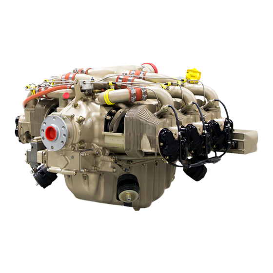
- Page 1 MAINTENANCE MANUAL TSIO-360-RB Courtesy of Bomar Flying Service www.bomar.biz PART NO. X30645A FAA APPROVED 1996 TELEDYNE INDUSTRIES, INC. OCTOBER 1996...
- Page 2 WARNING: Manufactured with 1,1,1 trichloroethane and /or CFC-113, substances which harm public health and the environment by destroying ozone in the upper atmosphere. This warning applies to all Teledyne Continental Motors fuel injection assemblies, manifold valve assemblies, regulator assemblies, magneto assemblies, starter adapters, oil pumps, oil coolers, accessory cases, crankcases, cylinder and valve assemblies, cylinder kits, bearings, turbochargers, turbocharger bearings and thrust collars, tubes, hoses, and exhaust systems and components.
- Page 3 WARNING If the user of this manual is uncertain whether all current revisions have been incorporated into the manual, contact Teledyne Continental Motors. Do not perform any operation, maintenance, installation or other operation until the manual is confirmed current. MODEL: TSIO-360-MB & -SB...
- Page 4 WARNING BACKGROUND. Replacement parts, materials and accessories may be sold as being of aircraft quality when actually the quality and origin of these units are unknown. Users of such units are usually unaware of potential hazards involved with replacement parts not eligible for use on certificated aircraft.
- Page 5 Prior to performing maintenance, the mechanic must meet requirements of FAR 65 and must follow FAR Parts 43, 91 and 145 as applicable. Use this manual in conjunction with Teledyne Continental Motors (TCM) service documents, related publications, accessory manufacturer's instructions, FAR and FAA Advisory Circulars.
- Page 6 Publication Table of Contents COVER PAGES PAGE Definition of Notes, Cautions and Warnings................ii CFC Warning Statement......................ii Status Page.........................iii Replacement Parts Warning ....................iv Notice to all users........................ v NOTE ... Contents of each chapter are listed in chapter "Chapter Contents" before each division. Chapter Index CHAPTER PAGE...
-
Page 7: Table Of Contents
CHAPTER 1 SECTION PAGE Scope ...................... 1-2 Related Publications ................1-2 Manual Revisions .................. 1-3 Service Reports and Inquires .............. 1-3 Description of Engine Model Code ............. 1-4 Definition of Terms................1-4 Engine Design Features ............... 1-4 General ....................1-9 Engine Specifications ................ -
Page 8: Scope
The following are related engine and accessory manuals. 1. Overhaul Manual for L/TSIO-360-RB Series Aircraft engine, Form X30596A Supplement No. 2. Illustrated Parts Catalog for L/TSIO-360-RB Series Aircraft Engine, Form XX30597A. Supplement No. 1 3. Operators and Installation Manual for L/TSIO-360-RB Series Aircraft Engine, Form X30644. -
Page 9: Manual Revisions
MANUAL REVISIONS Revisions to this manual will be furnished to purchasers who complete and return the registration post card in the front of this manual. Page iii, "Current Status of Pages," is updated at each revision. Remove and discard the old page iii. -
Page 10: Description Of Engine Model Code
The L//TSIO-360-RB series The L//TSIO-360-RB series engines are air cooled, having six horizontally opposed overhead inclined valve cylinders. The cylinder displacement of 360 cubic inches is achieved with a 4.4 inch bore and a 3.875 inch stroke. The L/TSIO-360-RB series engines are fuel injected. - Page 11 FIGURE 1-1. Engine Description L/TSIO-360-RB...
- Page 12 FIGURE 1-2. ENGINE DESCRIPTION L/TSIO 360-RB (Cont’d)
- Page 13 FIGURE 1-2. ENGINE DESCRIPTION L/TSIO 360-RB (Cont’d)
- Page 14 FIGURE 1-2. ENGINE DESCRIPTION L/TSIO 360-RB (Cont’d)
- Page 15 FIGURE 1-2. ENGINE DESCRIPTION L/TSIO 360-RB (Cont’d)
- Page 16 360-RB series aircraft engines. Consult the L/TSIO-360-RB Operator & Installation Manual, Form X30644 for additional operating procedures. For time between overhaul (TBO) for L/TSIO-360-RB series engines see section 5-2 and the latest TBO Service Bulletin (Overhaul Periods For All Teledyne Continental Aircraft Engines).
- Page 17 Above 40°F Ambient (Sea Level)....TCM Approved SAE 50 or Multi Viscosity Oil Temperature Limits Minimum for Take-Off..................100°F Maximum Allowable..................240°F Recommended Operational Range ............160 - 180°F Cylinder Head Temperature TSIO-360-RB Recommended maximum at cruise..............420°F Limit ........................460°F Turbine Inlet Temperature Maximum Continuous ..................1650°F Maximum, 60 seconds ..................1700°F Ignition Timing (Compression stroke, breaker opens) Right Magneto, degrees BTC................22°±1°...
- Page 18 ACCESSORY DRIVE RATIOS TO CRANKSHAFT Accessory Direction of Rotation* Drive Ratio Tachometer Magneto 1.5:1 Starter 24.73:1 * ** Propeller Governor Fuel Pump (Injection), Freon Compressor 1.545:1 * * * * * * * Accessory Drive Pad 1.545:1 WARNING Oil pressure is applied to the face of accessory drive pads. If gaskets, accessory or cover is not properly installed and hardware is not properly torqued oil leakage will occur.
- Page 19 CHAPTER 2 TOOLS AND EQUIPMENT Section Page General Information....................2-2 Possible Special Tool Procurement Sources............2-3 Special Tools ......................2-4...
- Page 20 GENERAL INFORMATION The mechanic should be equipped with a complete set of the necessary tools that include the following: 1. Wrenches - 1/4" through 1 1/4" 2. Common and Philips Head Screwdrivers 3. Pliers - Common Diagonal Cutters, Needle Nose, Duck Bill, Snap Ring 4.
- Page 21 POSSIBLE SPECIAL TOOL PROCUREMENT SOURCES - NOTICE - All tools in the "Special Tool" list are for reference only, and not for the purpose of promoting or suggesting tools to be purchased from the indicated sources. The following information is given as an aid for special tool procurement purposes.
- Page 22 COMPANY GENERAL PRODUCT SUMMARY APPROVED AIRCRAFT ACCESSORIES INC. Model 20 ATM-C Porta-Test Unit 29300 Goddard Road Romulus, Michigan 48174 (313) 946-5547 SPECIAL TOOLS Specific tools listed or equivalent tools marketed by other manufacturers are necessary for overhaul and maintenance of the aircraft engine. ITEM TOOL Section...
- Page 23 Courtesy of Bomar Flying Service ITEM TOOL www.bomar.biz Section 545-116 Dial Bore Gages available from Federal Tool Supply Co. Inc. 20-6 CFL10 Cylinder Hone available from Snap On Tools 20-6 No. 1675 Valve Seat Grinder Set "Sioux Brand" available from Aircraft Tool Supply 20-6 AEX 375 Valve Seat Grinder Pilot .437 Dia.
- Page 24 ITEM TOOL Section Borrough's 445, 18mm Spark Plug Tap or equivalent for straightening out damaged 20-6 threads 2769A13 Rosan® Stud Remover available from McMASTER-CARR Supply Co. 20-6 Rosan® is a registered trademark of Fairchild Aerospace Fastener Division 8074 Rosan® Lock Ring Installer available from Kent - Moore 8118 Rocker Arm Bushing Remover/Installer available from Kent - Moore 3610 Reamer Rocker Arm Bushing available from Kent - Moore 20-6...
- Page 25 CHAPTER 3 SEALANTS AND LUBRICANTS Sealants / Lubricants ........................3-2...
- Page 26 SEALANTS AND LUBRICANTS Aviation Engine Oil Ashless Dispersant Recommended Grade Above 40°F ambient air, sea level SAE 50 or Multi Viscosity Below 40°F ambient air, sea level SAE 30 or Multi Viscosity Manufacturer Brand Name BP Oil Corporation BP Aero Oil Castrol Castrol Aero AD Oil Castrol Limited (Australia)
- Page 27 Preservative Oil TYPE SUGGESTED SOURCES APPLICATION MIL-C-6529 Type II (Aeroshell Fluid 2F or equivalent), For Temporary storage (up to 90 days) MIL-P-46002 Grade 1 oil, (NOX RUST VCI-105 For Indefinite storage or equivalent) May be purchased through: Rock Island Lubricant & Chemical P.O.
- Page 28 Lubricants TYPE SUGGESTED SOURCES APPLICATION Approved Ashless Dispersant Oil See Aviation Engine Oil Ashless Cylinder studs and through bolts, Dispersant Table crankcase studs, connecting rod bolts nuts engine accessory studs unless otherwise specified CHAMPION® - Spark Plug Champion Products Spark plugs Thread Lubricant No.
- Page 29 Sealants TYPE SUGGESTED SOURCES APPLICATION K & W Copper Coat For Distributor information call: K & W Products Customer Phone: 1-800-423-9446 Loctite Teflon PS/T Pipe Sealant For Distributor information: Pipe threads, pressure relief Loctite Customer Service @ valve housing threads, tach drive Phone: 1-800-243-4874 threads, oil temperature control valve, studs that are exposed to...
- Page 30 Miscellaneous TYPE SUGGESTED SOURCES APPLICATION TCM P/N 626531-1 May be purchased through High temp. paint for cosmetic and your local TCM Distributor corrosion protection Enamel - Gold (1qt) TCM P/N 626531-2 Enamel - Gold (1 gal) May be purchased through Where applicable for lockwiring TCM P/N 535001S Lockwire -.032 in dia.
- Page 31 CHAPTER 4 AIRWORTHINESS LIMITATIONS This Airworthiness Limitations section has been FAA approved and specifies maintenance required under §§ 43.16 and 91.403 of the Federal Aviation Regulations unless an alternative program has been FAA approved. Federal Aviation Regulations §§ 43.16 and 91.403 require owner/operator compliance with all maintenance limitations in this section concerning mandatory replacement times, inspection intervals and other related procedures that are specific to this engine.
- Page 32 INTENTIONALLY LEFT BLANK...
- Page 33 CHAPTER 5 TIME LIMITS/OPERATIONAL INSPECTION/ENGINE TROUBLESHOOTING SECTION PAGE General ....................5-2 Overhaul Periods ................... 5-2 Operational Inspection................5-3 Test Operating Limits ................5-4 Time Interval Inspections............... 5-5 Scheduled Maintenance................ 5-6 Unscheduled Maintenance..............5-11 General Information................5-14 Engine Troubleshooting Chart............. 5-14...
-
Page 34: General
GENERAL The scheduled inspection and maintenance described in this section must be complied with in addition to all aircraft manufacturer and accessory manufacturer inspection and maintenance requirements. This manual does not contain inspection or maintenance requirements for supplemental type certificated components or systems. Such information must be obtained from the supplemental type certificate holder. - Page 35 OPERATIONAL CHECK LIST Check and record the following system data : Starter ......................_________ *Record RPM Drop for each magneto at 1700 (150 RPM 50 RPM ) ...._________ MAXIMUM AND SPREAD MAXIMUM *Propeller Operation at 1700............_________ *Or as specified in aircraft manufacturer's instructions. Increase engine to full power and record: Manifold Pressure................
-
Page 36: Test Operating Limits
TEST OPERATING LIMITS ITEM ENGINE MODEL ENGINE MODEL TSIO-360-RB LTSIO-360-RB * Full Throttle Speed- RPM 2600 2600 Manifold Pressure In. hg. Absolute 38.0 38.0 Idle Speed - RPM 700±25 700±25 Fuel Grade (Octane) 100LL/100 100LL/100 Fuel Flow at 140 - 150 140-150 Full Throttle (Lbs. -
Page 37: Time Interval Inspections
TIME INTERVAL INSPECTIONS Inspection procedures and maintenance information are provided in the individual system chapters. Engine mounted accessories not supplied by TCM may require servicing at specific intervals; some of these are alternators, pneumatic pumps, air / oil separators and stand-by generators. -
Page 38: Scheduled Maintenance
SCHEDULED MAINTENANCE 50-HOUR INSPECTION NOTE: Research and comply with the Service Publications and Airworthiness Directives. 1. Thoroughly inspect the engine for any signs of leakage. Clean engine exterior by spraying or brushing with a flame resistant solvent used for general cleaning of engine parts. - Page 39 CAUTION ... Failure to properly install the induction air filter will result in unfiltered air being ingested into the engine which will accelerate engine wear and reduce engine service life. 5. Inspect induction air box for security and deterioration in accordance with the aircraft manufacturer's instructions.
- Page 40 100-HOUR INSPECTION NOTE: Research and comply with the Service Publications and Airworthiness Directives. In addition to the items listed in 50 Hour the following inspections and maintenance must be performed. 1. Drain engine oil. Reinstall oil drain plug with new gasket, torque to 190 - 210 in. lbs. and safety.
- Page 41 WARNING Insure fuel selector is in the off position prior to removing the fuel metering unit inlet screen. 13. Inspect fuel nozzles, upper deck and fuel injection nozzle reference lines, hoses, manifolds and fittings for proper routing, support and signs of fuel stains. Inspect manifold valve for security of installation, proper venting and signs of fuel stains.
- Page 42 26. Visually inspect magneto pressurization filter for contamination. If filter element is white, it may be continued in service. If filter element has turned to yellow or red, element is contaminated and must be replaced. If there is visible moisture present in the filter canister the magnetos must be removed from the engine, disassembled and inspected for possible internal contamination and corrosion.
-
Page 43: Unscheduled Maintenance
UNSCHEDULED MAINTENANCE Unscheduled maintenance events include but are not limited to: PROPELLER STRIKES A propeller strike is: (1) any incident, whether or not the engine is operating, that requires repair to the propeller other than minor dressing of the blades or (2) any incident while the engine is operating in which the propeller makes contact with any object that results in a loss of engine RPM. - Page 44 b. Following loss of power during ground operation. c. Following momentary engine shutdown. d. During single engine operation for training purposes on twin engine aircraft. 3. Over priming and attempting engine start with the aircraft parked on an incline that negates the effective operation of the drain system.
- Page 45 c) Remove and inspect inside of rocker covers for debris. Inspect valve stem (keeper grooves) and valve keepers for condition, security and proper installation. Inspect valve springs, rocker arms, spring retainers, rotocoils, pushrods, etc. d) Perform a borescope inspection on all cylinders. e) If no discrepancies are noted, re-service engine, perform operational inspection and correct any discrepancies noted prior to returning the engine to service.
-
Page 46: Engine Troubleshooting Chart
GENERAL INFORMATION The troubleshooting chart which follows discusses symptoms which can be diagnosed and interprets the probable causes and the appropriate corrective actions to be taken. Troubleshooting for individual systems will be found in that particular section of Chapters 11 through 22. - Page 47 TROUBLE PROBABLE CAUSE CORRECTION Engine Will Not Run At Fuel injection system See Section 13-4, "Fuel Injection Idling Speed improperly adjusted System Troubleshooting." Air leak in intake manifold Torque loose connection or replace damaged part. See Section 14-5, "Induction System Maintenance." Rough Idling Fuel injection system See Section 13-4, "Fuel Injection...
- Page 48 TROUBLE PROBABLE CAUSE CORRECTION Engine Runs Rough At Loose mounting bolts or Torque mounting bolts. Replace High Speed damaged mount pads mount pads. See Section 21-5, "Crankcase Maintenance 'Engine Mounts.' " Plugged fuel nozzle jet Clean. See Section 13-5, "Fuel System Maintenance 'Fuel Nozzles.' "...
- Page 49 TROUBLE PROBABLE CAUSE CORRECTION High Cylinder Head Exhaust system gas leakage Locate and correct in accordance with Temperature (Cont’d) the airframe manufacturer's instructions. Engine compartment cooling Repair or replace in accordance with baffles in poor condition. the airframe manufacturer’s instructions. Exhaust valve leaking Repair cylinder.
- Page 50 TROUBLE PROBABLE CAUSE CORRECTION Incorrect fuel pump Check and adjust in accordance with adjustment and operation Chapter 23. Replace malfunctioning pumps. See Section 13-5, "Fuel System Maintenance 'Fuel Pump.' " Fluctuating Fuel Pressure Fuel gage line leak or air in Drain gage line and torque gage line connections in accordance with the...
- Page 51 TROUBLE PROBABLE CAUSE CORRECTION Malfunctioning ignition Inspect spark plugs for fouled system component electrodes, heavy carbon deposits, erosion of electrodes, improperly adjusted electrode gaps, and cracked porcelains. Test plugs for regular firing under pressure. Replace damaged or misfiring plugs. Gap spark plugs to spark plug manufacturer's specifications.
- Page 52 TROUBLE PROBABLE CAUSE CORRECTION Malfunctioning oil pump Replace oil pump. See Section 18-5, "Oil Pump." Weak or broken oil pressure Replace spring. Adjust pressure to relief valve spring 30-60 pounds per square inch in accordance with Chapter 23, "Oil Pressure Adjustment." High Oil Temperature Prolonged ground operation Limit ground operation to a minimum.
- Page 53 Preparation for Service................... 6-3 Engine Installation Instructions................6-4 Engine Pre-oiling ....................6-12 Preflight and Run-Up .................... 6-12 Flight Testing ......................6-13 FIGURE INDEX Installation Drawing L/TSIO-360-RB ..............6-6 Installation Drawing L/TSIO-360-RB (continued)........... 6-7 Installation Drawing L/TSIO-360-RB (continued)........... 6-8 Installation Drawing L/TSIO-360-RB (continued)........... 6-9...
- Page 54 INTENTIONALLY LEFT BLANK...
-
Page 55: General
GENERAL Technicians involved with engine preparation and installation into the airframe must possess a detailed knowledge of safe procedures used in engine servicing and the operation of ground support equipment. The engine must have a detailed visual inspection prior to installation in the airframe. UNPACKING Packaging Category "A"... -
Page 56: Preparation For Service
Remove the shipping plugs installed in the upper spark plug holes and inspect the cylinder bore with a borescope for rust or contamination. Contact your Teledyne Continental Motors Distributor if any abnormal condition is noted. -
Page 57: Engine Installation Instructions
ENGINE INSTALLATION INSTRUCTIONS (See Figures 6-1) CAUTION . . . The engine must be hoisted using the lifting eye brackets only. WARNING The aircraft fuel tanks and lines must be purged to remove all contamination prior to installation of the main fuel inlet line to the fuel pump. Failure to comply can cause erratic fuel injection system operation and damage to its components. - Page 58 FIGURE 6-1. INSTALLATION DRAWING...
- Page 59 FIGURE 6-1. INSTALLATION DRAWING (cont'd)
- Page 60 FIGURE 6-1. INSTALLATION DRAWING (cont'd)
- Page 61 FIGURE 6-1. INSTALLATION DRAWING (cont'd)
-
Page 62: Engine Pre-Oiling
ENGINE PRE-OILING It is important that all engine internal moving parts be properly lubricated before initial running of engine. Pre-oil engine prior to initial engine operation according to the following procedure: 1. Pre-oiling may be accomplished using a bladder type pressure pot capable of holding at least (1) gallon of clean aviation engine oil with an output pressure of 50 not to exceed 60 psi. -
Page 63: Flight Testing
discrepancies exist. After the operational inspection a test flight is required to insure that the engine and aircraft meet all of the manufacturer's performance and operational specifications prior to releasing the aircraft for normal service. WARNING Although the engine fuel system was adjusted at engine test, the fuel system must be checked and adjusted in accordance with Chapter 23 "Fuel System Adjustment,"... - Page 64 INTENTIONALLY LEFT BLANK 6-12...
- Page 65 CHAPTER 7 SERVICING FLUIDS SECTION PAGE Servicing, Oil......................7-2 Approved Engine Lubricating Oils................7-3 Fuel ......................... 7-3 Oil Filter Element Inspection .................. 7-4 Spectrographic Oil Analysis ................... 7-4 FIGURE PAGE Oil Servicing Points ....................7-2...
- Page 66 SERVICING OIL CAUTION . . . Some funnel-type quart oil containers incorporate a styrofoam or aluminum seal. Remove this seal from the container and discard it before adding oil to the engine. If the seal falls into the engine, engine damage and possible failure can result. The oil system must be serviced to capacity with the oil grades specified.
- Page 67 APPROVED ASHLESS DISPERSANT OILS : BP Oil Corporation BP Aero Oil Castrol Castrol Aero AD Oil Castrol Limited (Australia) Castrol Aero AD Oil Chevron U.S.A., Inc. Chevron Aero Oil Continental Oil Conco Aero S Delta Petroleum Company Delta Avoil Oil Exxon Company, U.S.A.
- Page 68 OIL FILTER ELEMENT INSPECTION Inspect oil filter element at each oil and filter change even if oil analysis is being used. Filter element inspection may identify internal engine wear that will not be identified through oil analysis. New, rebuilt, overhauled engines or engines that have had cylinders replaced will generally exhibit noticeable amounts of normal wear material at the first and second oil and filter change.
- Page 69 SPECTROGRAPHIC OIL ANALYSIS (continued) A proper spectrographic oil analysis program should begin with the first engine oil change. Establishing a wear trend data base for an engine will require analysis of at least three oil samples. As the engine accumulates operating time and additional oil samples are analyzed, a definitive wear trend can be identified.
- Page 70 INTENTIONALLY LEFT BLANK...
- Page 71 CHAPTER 8 ENGINE PRESERVATION AND STORAGE Section Page General ........................8-2 Engine Preservation ....................8-2 Temporary Storage....................8-2 Indefinite Storage ....................8-3 Indefinite Storage Inspection Procedures .............. 8-4 Returning An Engine To Service................8-4...
-
Page 72: General
GENERAL There is no practical procedure that will insure corrosion prevention on installed aircraft engines. Susceptibility to corrosion is influenced by geographical location, season and usage. The owner/operator is responsible to recognize the conditions that are conducive to corrosion and take appropriate precautions. ENGINE PRESERVATION Corrosive attack can occur in engines that are flown only occasionally regardless of geographical location. -
Page 73: Indefinite Storage
6. Seal all engine openings exposed to the atmosphere using suitable plugs and covers. 7. Tag each propeller in a conspicuous place with the following notation on the tag: DO NOT TURN PROPELLER - ENGINE PRESERVED - PRESERVATION DATE NOTE. . . If the engine is not returned to flyable status on or before the 90-day expiration, it must be preserved in accordance with "Indefinite Storage"... -
Page 74: Indefinite Storage Inspection Procedures
INDEFINITE STORAGE INSPECTION PROCEDURES 1. Aircraft prepared for indefinite storage must have the cylinder dehydrator plugs visually inspected every 15 days. The plugs must be changed as soon as they indicate other than a dark blue color. If the dehydrator plugs have changed color in one-half or more of the cylinders, all desiccant material on the engine must be replaced. - Page 75 CHAPTER 9 STANDARD PRACTICES SECTION PAGE General ......................9-2 Lockwire Procedure ................... 9-3 Tab Washer Procedure ..................9-5 Cotter Pin Procedure..................9-5 Application Of Adhesives ................... 9-6 Installation Of Gaskets ..................9-6 FIGURE PAGE General Lockwire Procedure................9-3 General Lockwire Patterns................9-4 Tab Washer Installation Procedure..............
-
Page 76: General
GENERAL To facilitate and insure proper reinstallation, tag or mark all parts and hardware as they are removed or disassembled. Tag any unserviceable parts or units for investigation and possible repair. Take extreme care to prevent foreign matter, lockwire, nuts, washers, dirt, etc., from entering the engine on or off the aircraft. -
Page 77: Lockwire Procedure
LOCKWIRE PROCEDURE Lockwiring is the securing together of two or more parts with lockwire which shall be installed in such a manner that any tendency for a part to loosen will be counteracted by additional tightening of the wire. Wire shall be pulled taut while being twisted and caution must be exercised during the twisting operation to keep the wire tight without over stressing. - Page 78 LOCKWIRE PROCEDURE (cont'd) Various examples of lockwiring are shown in Figure 9-2, "General Lockwire Patterns." 1. All items to be lockwired must be properly torqued. Applying torque that is above or below specified limits to obtain alignment of the holes is not permitted. 2.
-
Page 79: Tab Washer Procedure
TAB WASHER PROCEDURE Tab washers are installed by fitting a tab in a tab slot and bending the remaining tabs firmly against the bolt or nut flat. Tab washers are used in various locations in TCM engines and must not be reused after removal. The tabs that are provided to be bent up against the head flats must be seated firmly, with no scarring of the tabs. -
Page 80: General Cotter Pin Installation
FIGURE 9-4. GENERAL COTTER PIN INSTALLATION APPLICATION OF ADHESIVES Adhesives and sealants will be used as specified in this manual. WARNING The improper use of sealants and adhesives will cause engine malfunction or failure. Gasket Maker P/N 646942 must be applied in a thin even coat. Gasket Maker surfaces must be clean and free of oil and grit. - Page 81 CHAPTER 10 ENGINE MAINTENANCE 10-1 GENERAL During engine 50 and 100 hour inspections, if engine components must be remove and replaced, refer to the applicable disassembly/reassembly instructions found in the TSIO- 360 Series Overhaul Manual, Form OH-08 as outlined in Maintenance Section of each system.
- Page 82 INTENTIONALLY LEFT BLANK 10-2...
- Page 83 CHAPTER 11 EXHAUST SYSTEM SECTION PAGE 11-1 Exhaust System Description................11-2 11-2 Turbocharger Detailed Description..............11-4 11-3 Exhaust By-pass Valve (Wastegate) Detailed Description......11-5 11-4 Variable Absolute Pressure Controller (VAPC) Detailed Description ..11-6 11-5 Turbocharger Lubrication System ..............11-7 11-6 Exhaust System Inspection ................
-
Page 84: Exhaust System Description
11-1 EXHAUST SYSTEM DESCRIPTION The L/TSIO-360-RB exhaust system contains the following engine components: rear mounted turbocharger, hydraulic wastegate, lubrication plumbing, exhaust collector assembly, and turbocharger tailpipe assembly. During normal engine operation, exhaust gases exiting the cylinder combustion chambers, flow through the exhaust collector to the turbocharger turbine housing inlets. The exhaust gas flow provides turbine wheel rotation and exits through the turbine housing discharge port and tailpipe assembly. - Page 85 FIGURE 11-1. INDUCTION AND EXHAUST SYSTEM 11-3...
-
Page 86: Turbocharger Detailed Description
11-2 TURBOCHARGER DETAILED DESCRIPTION. The turbocharger consists of a radial inward flow turbine and turbine housing, a centrifugal flow impeller (compressor) and compressor housing, each bolted to a center housing. The center housing incorporates bearings that support the turbine/compressor shaft. The shaft and bearings are lubricated with pressurized engine oil that enters the center housing through an oil inlet check valve and fitting. -
Page 87: Exhaust By-Pass Valve (Wastegate) Detailed Description
11-3 EXHAUST BY-PASS VALVE (WASTEGATE) DETAILED DESCRIPTION. The Exhaust By-pass Valve or wastegate used on the L/TSIO-360-RB engine is an oil actuated, butterfly type valve. The exhaust by-pass valve butterfly valve is connected to the actuator by mechanical linkage. The exhaust by-pass valve is installed in the engines exhaust system, near the turbocharger, in an exhaust by-pass pipe that allows some of the exhaust gases to by-pass the turbocharger turbine. -
Page 88: Variable Absolute Pressure Controller (Vapc) Detailed Description
11-4 VARIABLE ABSOLUTE PRESSURE CONTROLLER (VAPC) DETAILED DESCRIPTION. The variable absolute pressure controller is designed to maintain deck pressures to provide sea level horsepower at varying altitudes. By means of a sensing port in the pneumatic section of the controller, the outside of the aneroid bellows is subjected to deck pressure. The aneroid bellows is linked to a poppet valve, spring loaded normally closed. -
Page 89: Turbocharger Lubrication System
11-5 TURBOCHARGER LUBRICATION SYSTEM Pressurized oil is supplied to the turbocharger from the engine. A fitting located in left crankcase half (2-4-6 cylinder side), below number 2 and 4 cylinder, oil gallery supplies pressurized engine oil to the turbocharger center housing oil inlet. Oil is return to the engine from the turbocharger center housing is accomplished by a scavenge pump contained in the starter adapter assembly. - Page 90 11-6 100 HOUR INSPECTION (continued) Multi-segment "V" Band Clamps, Figure 11-7. Clamps located between turbocharger and tailpipe should first be cleaned using crocus cloth on the outer band of clamp assembly. Inspect spot weld areas for cracks and looseness, inspect the corner radii of clamp inner segments for cracks using a flashlight and mirror.
-
Page 91: Wastegate
11-7 EXHAUST SYSTEM TROUBLESHOOTING This troubleshooting chart is provided as a guide. Review all probable causes given, check other listings of troubles with similar symptoms. Items are presented in sequence of the approximate ease of checking, not necessarily in order of probability. TROUBLE PROBABLE CAUSE CORRECTION... - Page 92 TROUBLE PROBABLE CAUSE CORRECTION Loss Aircraft's Critical Aftercooler plugged or damaged Repair or replace as required. Altitude (cont’d) Turbocharger Seals Worn or damaged seals Refer Turbocharger Leaking Manufacturer's Instructions Engine Oil Level Frequently Leaking Turbocharger check Replace check valves. Refer to Low After Servicing Prior to valves and seals Turbocharger...
- Page 93 Overhaul Manual X30596A. For maintenance of these components refer to the component manufacturer's instructions, Airesearch, 3201 Lomita Blvd. Torrance California, 90505. Lubrication Plumbing - Turbocharger lubrication plumbing must be replaced if deteriorated or leaking in accordance with the applicable Disassembly/Reassembly portions in the L/TSIO-360-RB Overhaul Manual, Form X30596A. 11-11...
- Page 94 INTENTIONALLY LEFT BLANK 11-12...
- Page 95 CHAPTER 12 IGNITION SYSTEM SECTION PAGE 12-1 Slick Ignition System Description ................. 12-2 12-2 Ignition System Component Detailed Description ..........12-2 12-3 Ignition System Inspection 50/100/500 Hour ............12-2 12-4 Ignition Troubleshooting ..................12-4 12-5 Ignition System Maintenance ................12-5 FIGURE PAGE 12-1...
-
Page 96: Slick Ignition System Description
12-1 SLICK IGNITION SYSTEM DESCRIPTION The L/TSIO-360 engines utilize two Slick (Unison) 6224 Series pressurized magnetos. The left magneto fires the 1-3-5-lower and the 2-4-6 upper spark plugs, while the right magneto fires the 1-3-5 upper and 2-4-6-lower spark plugs. The Slick 6224 Series pressurized magnetos, manufactured by Slick Electro Incorporated, 530 Blackhawk Park Avenue, Rockford, Illinois 61101, are designed to provide ignition for six cylinder light aircraft engines. - Page 97 12-3 IGNITION SYSTEM INSPECTION (continued) 100 HOUR INSPECTION - Perform all requirements of 50 hour inspection and the following: WARNING Magneto-to-engine timing maintenance does not insure magneto, harness and spark plug performance. Failure to properly maintain the magneto, harness and spark plugs will lead to internal engine damage and failure.
-
Page 98: Ignition Troubleshooting
12-3 IGNITION SYSTEM INSPECTION (continued) NOTE . . . Minor changes in magneto timing can be expected during normal engine service. The time and effort required to check and adjust the magnetos to specifications is slight and the operator will be rewarded with longer contact point life, smoother engine operation and less corrective maintenance between routine inspections. -
Page 99: Ignition System Maintenance
TROUBLE PROBABLE CAUSE CORRECTION Rough Idling Spark plugs fouled or improperly Clean spark plugs. Adjust spark gaped plug gap in accordance with spark plug manufacturer's specifications. Weak condenser Replace condenser in accordance with magneto manufacturer's instructions. Rough At Speeds Above Loose improperly gaped... -
Page 100: Magneto Accessory Drive Adapter
timing must be performed in accordance with the magneto manufacturer's instructions. See Slick Order Form F-1100. See Section 1-4", Related Publications" for ordering information. Magneto Drive Assemblies - Remove the magneto drive assemblies for repair or replacement in accordance with the applicable portion of the Magneto and Accessory Drive disassembly instructions in the L/TSIO-360 Overhaul Manual Form X30596A. - Page 101 Spark Plugs - Remove the spark plugs for cleaning or replacement in accordance with applicable portions of Ignition System Disassembly/Reassembly instructions in the TSIO- 360-MB &-SB Overhaul Manual, Form. After spark plugs are removed, clean and gap the spark plugs in accordance with the spark plug manufacturer's instructions and test. Replace any spark plug that does not meet the manufacturer's specifications.
-
Page 102: Spark Plug Wear
CYLINDER ROTATION CYLINDER CYLINDER NUMBER NUMBER FROM 1 TOP 6 BOTTOM 1 BOTTOM 6 TOP 2 TOP 5 BOTTOM 2 BOTTOM 5 TOP 3 TOP 4 BOTTOM 3 BOTTOM 4 TOP 4 TOP 3 BOTTOM 4 BOTTOM 3 TOP 5 TOP 2 BOTTOM 5 BOTTOM 2 TOP... - Page 103 12-5 IGNITION SYSTEM MAINTENANCE (Continued) NOTE . . . If the engine is equipped with a right angle drive starter adapter and does not freely turn in the opposite direction of normal rotation the starter motor must be removed from the starter adapter. Some right angle starter drive adapters incorporate an over-riding spring clutch design that restricts engine rotation in the opposite direction of normal rotation.
- Page 104 5. Slowly rotate the crankshaft in the opposite direction of normal rotation until the piston lightly touches the dead center locator. Observe reading on the disk under the pointer. NOTE: DIAL INDICATOR POSITIONS SHWON ARE EXAMPLES ONLY. POSITIONS ON THE PROTRACTOR/TIMING INDICATOR DISC WILL DIFFER FROM ENGINE TO ENGINE.
- Page 105 8. Remove the top dead center locator from the number 1 cylinder and find the compression stroke on the number 1 cylinder by placing a finger over the spark plug hole as the crankshaft is rotated. Continue rotating crankshaft on the compression stroke until the 0°...
- Page 106 POSI TI VE DEAD CENTER LOCATOR REMOVED. EXAMPLE: FULL ADVANCE FI RI NG POSI TI ON 2 0 BEFORE TOP DEAD CENTER. # 1 CYLI NDER NORMAL DI RECTI ON OF ROTATI ON. NOTE: THE PROTRACTOR/ TI MI NG I NDI CATOR SHOWN I S USED WI TH THE PROPELLER AND SPI NNER I NSTALLED.
- Page 107 C. Insure that the crankshaft is positioned in accordance with Section 12-6 "Placing Crankshaft In Timing Position." D. Insure that the magneto drive coupling bushings and retainers are properly installed. Place a new gasket on the magneto flange and install magneto carefully so that the drive coupling lugs mate with the slots of the drive bushings.
-
Page 108: Coating Insulating Sleeve
To prevent sticking of sleeves and to minimize twisting of ferrule coat insulating sleeves, use MS122N/C02 Spray, Miller-Stephenson Chemical Co., Inc., 16 Sugar Hollow Road, Danbury, Connecticut 06810. See Figure 12-9, "Coating Insulating Sleeve." NOTE . . . Hold ferrules while torquing or loosening spark plug coupling nuts to protect against twisting conduit or cable. -
Page 109: Ignition Wiring Diagram
UPPER UPPER SPARK PLUGS SPARK PLUGS ENGINE FIRING ORDER 1 6 3 2 5 4 MAGNETO FIRING ORDER 1 2 3 4 5 6 LEFT MAG RIGHT MAG LOWER LOWER SPARK PLUGS SPARK PLUGS FIGURE 12-10. IGNITION WIRING DIAGRAM 12-15... - Page 110 INTENTIONALLY LEFT BLANK 12-16...
- Page 111 Fuel Injection System Troubleshooting............13-6 13-5 Fuel System Maintenance ................13-7 FIGURE PAGE 13-1 Fuel Pump Description L/TSIO-360-RB............13-2 13-2 General Fuel Manifold Valve Description ........... 13-3 13-3 General Fuel Nozzle Description ..............13-3 13-4 General F/I Sealant Application ..............13-4 13-5 General Control Linkage Lubrication Points..........
- Page 112 13-2 FUEL INJECTION SYSTEM COMPONENT DETAILED DESCRIPTION (cont’d) Fuel Pump L/TSIO-360-RB (See Figure 13-1) Fuel enters the fuel pump inlet where it is directed to the fuel pump blades. The fuel pump blades create fuel flow and the fuel is directed to the fuel pump outlet. Fuel leaving the fuel outlet is directed through various fittings and fuel line to fuel servo assembly.
- Page 113 FIGURE 13-2. GENERAL FUEL MANIFOLD VALVE DESCRIPTION Fuel manifold Valve (See Figure 13-2) The fuel manifold valve body contains a fuel inlet, diaphragm chamber and outlet ports for fuel lines to the individual nozzles. The diaphragm is enclosed by a vented cover which retains the diaphragm loading spring.
- Page 114 FIGURE 13-3. FUEL NOZZLE DESCRIPTION Fuel nozzle (See Figure 13-3) The fuel discharge nozzle is located in the cylinder head. The nozzle outlet is screwed into the tapped fuel nozzle hole in the cylinder head. The nozzle body has a drilled central passage with a counterbore at each end.
- Page 115 WARNING Never clean nozzles with wire or other similar object. If nozzle jet is plugged and obstruction cannot be removed by solvent action REPLACE THE NOZZLE. 100 Hour- Perform all requirements under 50 hour inspection. The fuel nozzles must be removed, cleaned and visually inspected every three hundred hours of operation.
- Page 116 FUEL INJECTION SYSTEM INSPECTION (cont’d). WARNING Failure to comply with the following instructions can result in fuel system linkage and/or related component damage and subsequent loss of engine power. Inspect the operation of each engine related control, including the throttle, mixture, propeller and alternate air controls.
- Page 117 Lbs./Hr. Gal./Hr. Unmetered or (APPROX.) Propeller Pump Pressure (PSID) L/TSIO-360-RB 700 RPM IDLE 35-45 140-150 24.0 - 25.0 2600 RPM F/T NOTE . . . The fuel system must be adjusted using a calibrated Porta-Test Unit connected in accordance with the manufacturer’s instructions.
- Page 118 13-4 FUEL INJECTION SYSTEM TROUBLESHOOTING This troubleshooting chart is provided as a guide. Review all probable causes given, check other listings of troubles with similar symptoms. Items are presented in sequence of the approximate ease of checking, not necessarily in order of probability. TROUBLE PROBABLE CAUSE CORRECTION...
- Page 119 Fuel Nozzles- For replacement of fuel nozzles, see the applicable portion of disassembly and reassembly procedure in the L/TSIO-360-RB Overhaul Manual, Form X30596A. If nozzles are obstructed and ccanot be cleaned by soaking in lacquer thinner, methyl ethyl keytone or acetone for several hours and blown dry with compressed air, they must be replaced with new.
- Page 120 Whenever the fuel pump is removed from the engine the following Fits and Limits must be checked. CAUTION…When performing dimensional inspection the following “Service Limits” may be used. However, they are only intended as a guide for re-use when performing maintenance of the engine prior to values up to and including service limits may be re- used, however, judgment should be exercised considering the PROXIMITY of the engine to its recommended overhaul time.
- Page 121 CHAPTER 14 INDUCTION SYSTEM SECTION PAGE 14-1 Induction System Description................14-3 14-2 Overboost Valve Detailed Description ............. 14-3 14-3 Induction System Inspection 50/100 Hour ............14-4 14-4 Induction System Troubleshooting..............14-4 14-5 Induction System Maintenance ................ 14-5 FIGURE PAGE 14-2 Overboost Valve....................
-
Page 122: Induction System Description
14-1 INDUCTION SYSTEM DESCRIPTION See Figure 11-1, “Induction and Exhaust System Schematic,” for induction system components and induction air flow. The induction system is mounted above the engine. It serves to carry induction air to the individual cylinder intake ports. Engine components through which air flows following the aircraft air inlet filter/alternate air door are: turbocharger compressor, aftercooler, overboost/controller adapter, fuel servo unit throttle area, balanced manifold, induction tubes and cylinder intake ports. -
Page 123: Induction System Inspection 50/100 Hour
14-3 INDUCTION SYSTEM INSPECTION 50 HOUR - Visually inspect the induction manifold, aftercooler and overboost valve for security, safetying, leaks, cracks, and chafing. Inspect all induction tube connections for security and wear. Inspect all induction tube hoses for deterioration. Any attaching brackets exhibiting cracks must be replaced. - Page 124 INTENTIONALLY LEFT BLANK 14-4...
- Page 125 Air Conditioning System Description..............15-2 15-2 Air Conditioning System Component Detailed Detail Description ..................... 15-2 15-3 Compressor Bracket Inspection ............... 15-3 15-4 Air Conditioning Troubleshooting ..............15-3 15-5 Compressor Bracket Maintenance..............15-3 FIGURE PAGE 15-2 Compressor Drive (TSIO-360-RB) ..............15-2 15-1...
- Page 126 15-1 AIR CONDITIONING SYSTEM DESCRIPTION Air Conditioning – The TSIO-360-RB engine utilizes a compressor mounting kit for the addition of a customer supplied belt driven compressor and air conditioning system. For a description of the complete air conditioning system refer to the airframe manufacturer’s information.
- Page 127 15-3 COMPRESSOR BRACKET INSPECTION 50-Hour – Visually inspect the compressor bracket assembly for security and cracks. The drive belt, customer supplied, air conditioning components, plumbing and connections must be inspected in accordance with the airframe manufacturer’s instructions. 15-4 AIR CONDITIONING SYSTEM TROUBLESHOOTING See the Airframe Manufacturer’s Instructions 15-5 COMPRESSOR MOUNTING KIT MAINTENANCE...
- Page 128 INTENTIONALLY LEFT BLANK 15-4...
- Page 129 CHAPTER 16 ELECTRICAL SYSTEM SECTION PAGE 16-1 Electrical Charging System Description............16-2 16-2 Electrical Charging System Component Detailed Description ..... 16-2 16-3 Charging System Inspection 50/100 Hour............16-2 16-4 Charging System Troubleshooting ..............16-2 16-5 Charging System Maintenance................. 16-2 16-1...
- Page 130 16-1 ELECTRICAL CHARGING SYSTEM DESCRIPTION The L/TSIO-360-RB engines incorporate provisions on the right front crankcase half for mounting a belt driven alternator. The alternator generates electrical current for powering the aircraft electrical system. For description of the aircraft electrical and charging system see the applicable Airframe manufacturer’s Instructions.
- Page 131 16-2 ELECTRICAL CHARGING SYSTEM COMPONENT DETAILED DESCRIPTION Alternator - For a detailed description of TCM alternators see TCM Form No. X30531-3," Alternator Service Instructions." See Section 1-4," Related Publications" for ordering information. 16-3 CHARGING SYSTEM INSPECTION 50 Hour - Visually inspect the alternator mounting hardware for security and corrosion. Inspect the alternator and mounts for cracks.
- Page 132 INTENTIONALLY LEFT BLANK 16-4...
- Page 133 Starting System Maintenance ............... 17-4 FIGURE PAGE 17-1 Starter And Starter Drive Adapter Description..........17-2 17-2 Starter Adapter Description ................17-3 17-3 Starter Adapter Fits And Limits (L/TSI0-360-RB and Optional TSIO-360-RB) ..........17-5 17-4 Starter Adapter Fits And Limits(TSI0-360-RB) .......... 17-7 17-1...
-
Page 134: Starter And Starter Adapter Description
17-1 STARTER AND STARTER ADAPTER DESCRIPTION The L/TSIO-360-RB engines utilize a starting system that employs an electric starter motor mounted on a right angle drive adapter. As the starter motor is electrically energized, the adapter worm shaft and gear engage the starter shaftgear by means of a spring and clutch assembly. -
Page 135: Starter And Starter Adapter Inspection
WORM WHEEL SCAVENGE PUMP GEAR SHAFT GEAR COVER CRANKCASE BUSHING SCAVENGE PUMP NEEDLE GEAR BEARING ROLLER BEARING STANDARD STARTER ADAPTER L/TSIO-360-RB WORM DRIVE GEAR AND SHAFT BALL BEARING NEEDLE BEARING STARTER MOTOR ADAPTER HOUSING SCAVENGE PUMP CLUTCH SPRING GEAR BEARING... -
Page 136: Starting System Troubleshooting
17-4 STARTING SYSTEM TROUBLESHOOTING This troubleshooting chart is provided as a guide. Review all probable causes given. Check other listings of troubles with similar symptoms. Items are presented in sequence of the approximate ease of checking, not in order of probability. TROUBLE PROBABLE CAUSE CORRECTION... - Page 137 Scavenge pump drive gear in starter shaftgear ..............Diameter 0.004 Starter shaftgear in scavenge pump cover ................Diameter 0.004L Scavenge pump driven gear to drive gear ................Backlash 0.027 FIGURE 17-3. STARTER ADAPTER FITS AND LIMITS (LTSIO-360-RB and OPTIONAL TSIO-360-RB) 17-5...
- Page 138 17-5 STARTING SYSTEM MAINTENANCE (cont'd) Ref. Description Serviceable Limit Starter shaftgear in bearing ..................Diameter 0.0045 Starter shaftgear front (bearing) journal..............Diameter 1.059 Starter shaftgear in needle bearing..................0.0031L Starter shaftgear in accessory drive adapter bushing............. 0.002L Bushing in adapter cover ......................0.003T Gearshaft housing oil seal bore ....................
- Page 139 FIGURE 17-4. STARTER ADAPTER FITS & LIMITS 17-7...
- Page 140 INTENTIONALLY LEFT BLANK 17-8...
- Page 141 CHAPTER 18 ACCESSORY CASE SECTION PAGE 18-1 Accessory Case....................18-2 18-2 Accessory Case Detailed Description..............18-2 18-3 Accessory Case Inspection .................. 18-4 18-4 Accessory Case Troubleshooting ................ 18-4 18-5 Accessory Case Maintenance................18-4 FIGURE PAGE 18-1 Accessory Case Description ................18-3 18-1...
- Page 142 See Figure 18-1 for accessory locations. A machined, threaded boss is located on the lower right hand side of the L/TSIO-360-RB and lower left hand side of the TSIO-360-RB accessory case for installation of an oil pressure relief valve. The front face of the accessory case is machined flat to mate with the crankcase.
- Page 143 FIGURE 18-1. ACCESSORY CASE DESCRIPTION 18-3...
- Page 144 18-3 ACCESSORY CASE INSPECTION 50 Hour - Visually inspect accessories for security and all gasket areas for oil leaks. All accessory studs must be visually inspected and checked for security. Safety mechanisms such as lockwire and locking tab washers must be inspected for proper installation and security.
- Page 145 CHAPTER 19 LUBRICATION SYSTEM SECTION PAGE 19-1 Lubrication System Description................19-2 19-2 Lubrication System Component Detailed Description Oil Pump ....................... 19-4 Oil Cooler and Oil Temperature Control Valve ............ 19-6 Oil Sump ....................... 19-7 Oil Suction Tube ....................19-7 19-3 Lubrication System Inspection ................
-
Page 146: Lubrication System Description
19-1 LUBRICATION SYSTEM DESCRIPTION The engine oil supply is contained in the oil sump. Oil is drawn from the sump through the oil suction tube to the intake side of the engine driven, gear type, oil pump. From the outlet side of the pump, oil passes to an oil pressure relief valve installed in the oil gallery in the accessory case. - Page 147 FIGURE 19-1 LUBRICATION SYSTEM SCHEMATIC 19-3...
-
Page 148: Lubrication System Component Detailed Description
19-2 LUBRICATION SYSTEM COMPONENT DETAILED DESCRIPTION Oil Pump - The oil pump is a positive displacement pump that consists of two meshed steel gears that revolve inside the oil pump cavity machined in the accessory case. The camshaft drives the oil pump drive gear, which drives the oil pump driven gear. The oil pump driven gear is supported by a shaft pressed into the accessory case and supported by the oil pump cover plate. - Page 149 ACCESSORY CASE INTERNAL VIEW TSIO-360 FIGURE 19-2. OIL PUMP DESCRIPTION TSIO-360 19-5...
- Page 150 ACCESSORY CASE INTERNAL VIEW LTSIO-360 FIGURE 19-3. OIL PUMP DESCRIPTION LTSIO-360 19-6...
-
Page 151: Oil Cooler And Oil Temperature Control Valve
19-2 LUBRICATION SYSTEM COMPONENT DETAILED DESCRIPTION (continued) Oil Cooler And Oil Temperature Control Valve - Oil flowing from the oil filter enters the oil cooler inlet, oil temperature control valve cavity. When the oil is below normal operating temperature, the oil temperature control valve (vernatherm) is open allowing oil to flow through the by-pass portion of the oil cooler adapter. -
Page 152: Oil Suction Tube
19-2LUBRICATION SYSTEM COMPONENT DETAILED DESCRIPTION (continued) Oil Sump - The oil sump is cast aluminum. The sump is attached to the crankcase flange with 14 nuts, washers and lock washers. The oil sump assembly incorporates a tapped drain plug boss. The drain plug boss has provisions for safety wiring of the oil drain plug. Oil Suction Tube - The oil suction tube is threaded into the oil sump and sealed to the accessory case by the accessory case gasket. - Page 153 FIGURE 19-6. STUD IDENTIFICATION D. After extension height inspection, remove the stud from the adapter. Clean the threads of the adapter housing and stud with Loctite "Primer T" (TCM P/N 646944) and allow to dry. E. Apply a line of Loctite 271 (TCM P/N 646941) along the large threads (.8125- 16 end) of the stud and install into the adapter finger tight to 30 inch pounds torque.
-
Page 154: Lubrication System Troubleshooting
Using an oil filter can cutter (See Chapter 2 Tools), open filter can and inspect filter element for debris. If no foreign particles are present, insure oil filter adapter is clean, lubricate oil filter seal using Dow Corning® DC-4 compound and install new oil filter. Torque oil filter to 192-216 inch pounds. - Page 155 TROUBLE PROBABLE CAUSE CORRECTION High Oil Temperature Indication Oil viscosity too high Drain and refill with correct seasonal (cont’d) weight. See Chapter 7, "Servicing Oil". Prolonged ground operation Limit ground operation to a minimum, refer to airframe manufacturer's operating instructions. Malfunctioning gauge or bulb unit Check wiring.
- Page 156 maintenance the oil suction tube screen must be cleaned and all lower internal hardware inspected for security and safetying. Oil sumps that are warped or cracked must be discarded. 19-5 LUBRICATION SYSTEM MAINTENANCE (continued) Oil Suction Tube - The oil sump and accessory case must be removed to gain access to the oil suction tube.
- Page 157 used when overhauling an engine. See the current L/TSIO-360 Series Overhaul Manual Form X30596A for minimum fits and limits. 19-5 LUBRICATION SYSTEM MAINTENANCE (continued) If the accessory case is removed from the engine the following components must be dimensionally inspected. SERVICEABLE REF.
- Page 158 INTENTIONALLY LEFT BLANK 19-14...
- Page 159 CHAPTER 20 CYLINDER ASSEMBLY SECTION PAGE 20-1 Cylinder Cooling ....................20-2 20-2 Cylinders, Pistons And Valve Train ..............20-4 20-3 Cylinder Assembly Detailed Description ............20-4 20-4 Cylinder Assembly Inspection 50/100 Hour............20-7 20-5 Cylinder Assembly Troubleshooting ..............20-13 20-6 Cylinder Assembly Maintenance ..............20-15 FIGURE PAGE 20-1 Engine Cooling Airflow Diagram...............20-2...
-
Page 160: Cylinder Cooling
20-1 CYLINDER COOLING Cylinder cooling is accomplished by transferring heat from the cylinder barrel and cylinder head cooling fins to the surrounding airflow. The engine cowling, inner cylinder baffles, peripheral baffles and baffle seals direct cooling airflow evenly around the cylinders providing uniform cylinder temperatures. - Page 161 20-2 CYLINDERS, PISTONS AND VALVE DRIVE TRAIN The cylinders, pistons and valve train are the portion of the engine that develop power. The cylinder combustion chamber provides a controlled area for burning fuel/air mixture and converting that heat energy into mechanical energy. Aviation fuel and air is drawn into a cylinder during the intake stroke, compressed by the piston during the compression stroke and then ignited by a high intensity spark from the spark plug.
-
Page 162: Cylinder Assembly Detailed Description
20-3 CYLINDER ASSEMBLY DETAILED DESCRIPTION Cylinder, Valve Guides, Valves, Rotocoils - The externally finned aluminum alloy head castings are heated and valve seat inserts installed before the head is screwed and shrunk onto an externally finned steel alloy barrel to make the permanent head and barrel assembly. - Page 163 20-3 CYLINDER ASSEMBLY DETAILED DESCRIPTION (continued). Piston - Pistons are aluminum alloy castings with a steel insert cast into the top ring groove. Pistons have three ring grooves above the pin hole and one ring groove below. Compression rings are installed in the top, and second grooves. The groove below the pin hole contains an oil scraper.
- Page 164 20-3 CYLINDER ASSEMBLY DETAILED DESCRIPTION (continued). Valve Rocker arms, Shafts, Pushrods And Housings (Valve Train) - Valve rocker arms are steel forgings with hardened pushrod sockets and rocker faces. The rocker arm has a precision bronze bushing that accommodates the rocker shaft. The rocker arm shaft is secured to the rocker boss studs using retainers, lock tabs and nuts.
- Page 165 20-3 CYLINDER ASSEMBLY DETAILED DESCRIPTION (continued). Hydraulic Tappet - See Figure 20-6. The barrel type hydraulic valve tappet consists of a steel body (1), an expanding spring (2), a check valve assembly (3, 4 and 5), a plunger (6), a socket (7) and a retaining ring (8). A groove (9), around outside of the body picks up oil from the crankcase oil gallery.
- Page 166 The compression testing equipment must be calibrated and used in the proper manner to insure accurate results. To accurately accomplish a leakage check, use the following information on leakage and use the Master Orifice tool to calibrate the leakage checking equipment used on Teledyne Continental engines. FACTORY CALIBRATED ORIFICE (CLEAN With Soft Brush.
- Page 167 80 pounds per square inch. The pressure in both gages should stabilize with no leakage. The restrictor orifice dimension in the Master Orifice Tool for Teledyne Continental aircraft engines must be 0.040 inch orifice diameter, 0.250 inch long with 60° approach angle, and must flow 120 ±5 cubic feet per hour at 30 pounds per square inch differential pressure.
- Page 168 20-4 (cont'd) Master Orifice Tool For conformity in testing equipment a Master Orifice Tool, Part Number 646953, has been developed to calibrate equipment and determine the low indicated leakage limit prior to the engine leakage check. Connect compressed air at 100 - 120 pounds per square inch to the tester with cylinder pressure valve closed.
- Page 169 1. Perform the test as soon as possible after the engine is shut down to insure that the piston rings, cylinder walls, and other engine parts are well lubricated and at operating conditions. 2. Turn the crankshaft by hand in the direction of rotation until the piston, in the cylinder being checked, is coming up on its compression stroke.
- Page 170 10. If the leakage is below the previously determined low cylinder gauge reading, loss past the dynamic seal may be due to piston ring end gap alignment or by the piston and piston rings angular direction in the cylinder bore see Figure 20-11,"Ring Positioning." First insure that the piston and piston rings are centered.
-
Page 171: Cylinder Assembly Troubleshooting
COMPRESSION TEST TROUBLESHOOTING CORRECTIVE FIRST CHECK CHECK FOR METHOD CONDITIONS ACTION STATIC SEAL Intake Valve to Listen for air flow Carbon Stake Valve (NO LEAKAGE seat seal in intake port Cracked Cylinder Replace cylinder PERMISSABLE Seat worn or burned Reface or replace Valve worn or burned Reface or replace Exhaust valve to... - Page 172 TROUBLE PROBABLE CAUSE CORRECTION Valve seats worn and leaking,, piston See Section 20-6 Cylinder Assembly rings worn or stuck in ring lands Maintenance "Cylinders." Low Compression Piston rings excessively worn See Section 20-6 Cylinder Assembly Maintenance "Cylinders." Valve faces and seats worn See Section 20-6 Cylinder Assembly Maintenance "Cylinders."...
- Page 173 NOTE. . . Excessive crankcase pressure in flight can be caused by ram air entering the engine interior through an improper fitting oil cap seal and/or damaged crankshaft nose seal. AIRSPEED VERSUS WATER PRESSURE (Inches H 50MPH= 1.23 Limits for TSIO-360 60 MPH= 1.77 70 MPH=...
-
Page 174: Cylinder Assembly Service Limits
Cylinder Baffling - Refer to the airframe manufacturer's instructions. Before any repair procedures are performed after cleaning, the cylinder and it's related components must be visually, fluorescent penetrant and magnetic particle Inspected as applicable in accordance with the L/TSIO-360 Series Overhaul Manual, Form X30596A. CAUTION. - Page 175 Ref. Description Servicable Limit Max. CYLINDER AND HEAD ASSEMBLY Rocker arm grind..................Width: 0.34 Intake valve in guide................Diameter: 0.0050L Exhaust valve in guide .................Diameter 0.0057L Intake valve face (to stem axis)..............Angle: 60° - 15° Exhaust valve face (to stem axis) ............Angle: 45°...
- Page 176 FIGURE 20-12. CYLINDER ASSEMBLY SERVICE LIMITS (For “Maintenance Cylinder Dimensions,” (see next page) 20-18...
- Page 177 TSIO-360 SERIES CAUTION. . . Cylinder assemblies exceeding new parts dimension shown are acceptable when performing maintenance before engine overhaul. However, piston ring gaps given in the table of limits must be maintained. When engine is being overhauled TCM requires that all Parts be brought back to new parts limits by rework or replacement.
- Page 178 20-6 CYLINDER ASSEMBLY MAINTENANCE (continued) Single Cylinder Reassembly - After all cylinder components have been cleaned, inspected and repaired in accordance with TCM specifications, reassemble cylinder in accordance with Cylinder and Piston Sub-Assembly of the L/TSIO-360 Series Overhaul Manual, Form X30596A. Single Cylinder Reinstallation - Reinstall repaired or new cylinder in accordance with the L/TSIO-360 Series Overhaul Manual, Form X30596A.
- Page 179 CHAPTER 21 CRANKCASE ASSEMBLY SECTION PAGE 21-1 Crankcase Description ..................21-2 21-2 Crankcase Detailed Description................21-2 21-3 Crankcase Inspection 50/100 Hour..............21-3 21-4 Crankcase Troubleshooting ................. 21-5 21-5 Crankcase Maintenance..................21-5 FIGURE PAGE 21-1 Crankcase Description ..................21-2 21-2 Inspection of Crankcase Non Critical Area ............21-3 21-3 Inspection of Crankcase Critical and Non Critical Areas ........
- Page 180 21-1 CRANKCASE DESCRIPTION The crankcase provides a tight enclosure and oil galleries for lubrication. The crankcase is sufficiently rigid to provide support for the crankshaft, camshaft and bearings. 21-2 CRANKCASE DETAILED DESCRIPTION Two aluminum alloy castings are joined along the vertical center plane to form the complete crankcase.
- Page 181 FIGURE 21-1. CRANKCASE DESCRIPTION 21-3...
- Page 182 21-3 CRANKCASE INSPECTION 50 HOUR - Visually inspect accessories for security and all gasket areas for oil leaks. All accessory and cylinder mounting studs must be visually inspected and checked for security. Safety mechanisms such as lockwire and locking tab washers must be inspected for proper installation and security.
- Page 183 FIGURE 21-3. INSPECTION OF CRANKCASE CRITICAL (GRAY) AND NON CRITICAL (DARK GRAY) AREAS 21-3 CRANKCASE INSPECTION (continued) CAUTION. . . Repair of the crankcase must be performed by FAA approved repair facilities only. TCM has established that welding of the crankcase is an acceptable repair process. The weld procedure must conform with approved FAA repair standards and the dimensional integrity of the crankcase must be maintained.
- Page 184 21-4 CRANKCASE TROUBLESHOOTING This troubleshooting chart is provided as a guide. Review all probable causes given. Check other listing of troubles with similar symptoms. Items are presented in sequence of the approximate ease of checking, not necessarily in order of probability. TROUBLE PROBABLE CAUSE CORRECTION...
- Page 185 NOTE. . . Exercise judgment in determining how far systems and components should be disassembled. Any maintenance of engine systems and components removed from engine must be performed in accordance with that particular system or component section of this manual. CAUTION.
- Page 186 INTENTIONALLY LEFT BLANK 21-8...
- Page 187 CHAPTER 22 ENGINE DRIVE TRAIN SECTION PAGE 22-1 Engine Drive Train Description................22-2 22-2 Engine Drive Train Component Detailed Description .......... 22-3 22-3 Engine Drive Train Inspection ................22-5 22-4 Engine Drive Train Troubleshooting..............22-5 22-5 Engine Drive Train Maintenance................22-6 FIGURE PAGE 22-1...
-
Page 188: Engine Drive Train Description
22-1 ENGINE DRIVE TRAIN DESCRIPTION When starting engine, torque is transmitted from the starter (12) through adapter components (13, 14, 15 & 16) to crankshaft gear (1). As worm-wheel (15) is turned, the spring mounted on its hub, is tightened to grip drum of shaftgear (16). After engine is started the spring returns to its normal position releasing the shaftgear and disengaging the starter. -
Page 189: Engine Drive Train Component Detailed Description
22-2 ENGINE DRIVE TRAIN COMPONENT DETAILED DESCRIPTION Crankshaft - The crankshaft has four, machined, main journals which are supported by precision bearing inserts in each of the four bearing saddles machined in the crankcase. Six machined rod journals provide attachment of the connecting rod assemblies. Figure 22-2 shows the method of numbering the crankshaft main journals, connecting rod journals and crankshaft cheeks which are identified by letters and location numbers. - Page 190 Connecting Rod - The connecting rods are made of aircraft quality steel. The connecting rod large diameter end, which attaches to the crankshaft crankpin or rod journal, is fitted with a cap and two (2) piece bearing. The bearing cap is held to the main rod by special bolts and nuts. A split steel backed bronze bushing is pressed into the piston pin end and machined for a precision fit.
-
Page 191: Engine Drive Train Inspection
22-3 ENGINE DRIVE TRAIN INSPECTION 50 Hour - Visually inspect the front crankshaft exit area for evidence of oil leakage, corrosion or pitting and any obvious over stressing of the crankshaft and flange. Visually inspect propeller installation in accordance with the airframe manufacturer's Instructions. 100 Hour - Perform visual inspection requirements of 50 hour inspection. -
Page 192: Crankshaft Oil Seal
DIRECTION OF PATTERN MARKS (30°) THIS DISTANCE 1” FIGURE 22-5. HELIX PATTERN APPLICATION TSIO-360 4. See Figure 22-5, "Helix Pattern Application." Apply helix using a strip of 180 grit emery cloth approximately one half inch wide. Do approximately one quarter of the surface indicated at a time, stroking the cloth outward toward the propeller flange in the direction of rotation (CCW) towards you using maximum hand pressure. - Page 193 FIGURE 22-6. CRANKSHAFT OIL SEAL Engine Drive Train Component Removal - If all other probabilities have been evaluated and it is determined a malfunction is occurring with internal engine components, the engine must be removed from the airframe in accordance with the L/TSIO-360 Series Overhaul Manual, Form X30596A and the airframe manufacturer's instructions.
- Page 194 INTENTIONALLY LEFT BLANK 22-8...
- Page 195 CHAPTER 23 POST MAINTENANCE ADJUSTMENT AND TEST SECTION PAGE 23-1 Post Maintenance Operational Test..............23-2 23-2 Engine Adjustment And Setup ................23-4 23-3 Test Flight ......................23-12 FIGURE PAGE 23-1 General Oil Pressure Adjustment................. 23-4 23-2 Fuel Pump Adjustment - Idle Speed ..............23-5 23-3 Fuel Servo Adjustments ..................
- Page 196 23-1 POST MAINTENANCE OPERATIONAL TEST STARTING WARNING Over priming can cause hydrostatic lock and subsequent engine malfunction. CAUTION. . . Insure propeller area is clear before initiating starting sequence. NOTE. . . If engine has had a new cylinder or cylinders and piston rings installed, start the engine in accordance with the airframe manufacturer's Airplane Flight Manual (AFM.) Operate the engine at 750 RPM for one minute, gradually increasing RPM to 1000 RPM in three minutes.
- Page 197 Positive Fuel Cutoff ......................__________ When propeller stops rotating, place ignition switch, master switch and fuel selector in off position. TABLE 23-1. OPERATING LIMITS ENGINE MODEL ITEM L/TSIO-360-RB Full Throttle Speed - RPM 2600 Idle Speed - RPM Fuel Grade (Octane) 100LL/100 Fuel Flow at Full Throttle (Lbs.
- Page 198 23-2 ENGINE ADJUSTMENT AND SETUP Oil Pressure Adjustment The adjusting screw is turned clockwise to increase oil pressure and counterclockwise to decrease oil pressure. With normal operating oil temperature (180° - 200°F), adjust oil pressure to maintain, 30-80 pounds per square inch at full power RPM. Torque locknut and safety as required.
- Page 199 23-2 ENGINE ADJUSTMENT AND SETUP (continued) Fuel System Adjustment Verify that the aircraft fuel system is operating properly in accordance with the airframe manufacturer's instructions before performing any engine fuel system setup procedures. Adjust the engine fuel system as follows: NOTE : .
- Page 200 c. Repeat static runup and readjust pressure as required to obtain fuel pump pressure of 35 to 45 psig. Idle Mixture: Check and adjust idle mixture as follows: Idle Performance a. Operate the engine at 1500 to 1800 rpm until cylinder head temperatures are 250° F to 350°...
- Page 201 Idle Speed: Check and adjust idle speed as follows: a. Operate the engine at 1500 to 1800 rpm until cylinder head temperatures are 250° F to 350° F and the oil temperature is 160° F to 180° F. b. Reduce engine speed and stabilize it at 700 ± 25 rpm. c.
- Page 202 FIGURE 23-5. ADMP VS. OIL TEMPERATURE c. Adjust fuel flow rates: Set the engines to 2600 rpm, the manifold pressure to 38.0 Hg. And the mixture controls to full rich. Adjust fuel flow rates to the range of 24.0 to 25/0 gallons per hour with the fuel flow adjustment knob that is located on the top, left side of the FSA-5 fuel servo.
- Page 203 FIGURE 23-6. CONSTANT SPEED SEA LEVEL PERFORMANCE CURVE 23-9...
- Page 204 FIGURE 23-7. FUEL FLOW VS. METERED FUEL PRESSURE 23-10...
- Page 205 FIGURE 23-8. FUEL FLOW VS. BRAKE HORSEPOWER 23-11...
- Page 206 23-3 TEST FLIGHT Ambient air and engine operating temperatures are of major concern during this test flight. Do a normal pre-flight run-up in accordance with the Airplane Flight Manual. Conduct a normal take-off with full power and monitor the fuel flow, RPM, oil pressure, cylinder head temperatures and oil temperatures.
Need help?
Do you have a question about the TSIO-360-RB and is the answer not in the manual?
Questions and answers