Table of Contents
Advertisement
Quick Links
Advertisement
Table of Contents

Related Manuals for MFJ Enterprises Versa-Tuner II

Summary of Contents for MFJ Enterprises Versa-Tuner II
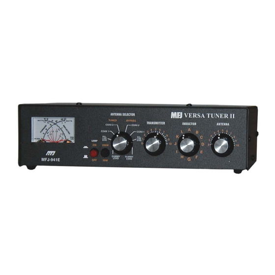
- Page 1 Model MFJ-941EK INSTRUCTION MANUAL CAUTION: Read All Instructions Before Operating Equipment MFJ ENTERPRISES, INC. 300 Industrial Park Road Starkville, MS 39759 USA Tel: 662-323-5869 Fax: 662-323-6551 COPYRIGHT 2013 MFJ ENTERPRISES, INC. VERSION 1A...
- Page 2 Customers using this manual should report errors omissions, recommendations for improvements, or other comments to MFJ Enterprises, 300 Industrial Park Road, Starkville, MS 39759. Phone: (662) 323-5869; FAX: (662) 323-6551. Business hours: M-F 8-4:30 CST.
-
Page 3: General Information
General Information: This manual contains all the information you'll need to build, calibrate, and use your new MFJ-941EK Versa-Tuner II kit. The Versa-Tuner II is actually four very useful station accessories combined into one package. The first is MFJ's wide- range 300-Watt T-network that can match virtually any HF antenna you're likely to encounter. - Page 4 MFJ-941EK Tuner Kit Instruction Manual INTRODUCTION Before soldering, always inspect leads and terminals for oxidation. If dull, clean or burnish them with a small brass-wire hobby brush or glass-fiber brush (available at Radio Shack). Clean surfaces and good heat distribution are the keys to strong solder.
- Page 5 MFJ-941EK Tuner Kit Instruction Manual INVENTORY Begin your inventory with the hardware bag. For identification purposes, PH = Phillips Head, SM = Sheet Metal Screw, SS = stainless steel, KEP = nut with an integral lock washer, OD = Outside Diameter, and ID = Inside Diameter. Qty Description MFJ Part Number 4-40 x 3/8"...
- Page 6 MFJ-941EK Tuner Kit Instruction Manual INVENTORY Next, inventory the circuit board bag containing small pc-board components and pre-cut wire. Color codes and number codes are included to help you sort resistors, capacitors, and chokes. Qty Description MFJ Part Number 100Ω 1/4W Resistor (brown, black, brown) 100-2100 150Ω...
- Page 7 MFJ-941EK Tuner Kit Instruction Manual INVENTORY This list covers the large item bag of larger items: Qty Description MFJ Part Number PC Board, Single-Sided 861-0949E Insulated Binding Post, Red, with Hardware 606-0003 SO-239 UHF Chassis Mount Connectors 610-2005 300-W 4:1 Balun on 1" Toroid Form 10-10002B 2-1/2"...
-
Page 8: Circuit Board Assembly
MFJ-941EK Tuner Kit Instruction Manual CONSTRUCTION Key Assembly Instructions: Key words are used to shorten the length of the assembly steps to one line. Find means to pull specific items from the parts inventory for installation. Identify means to look for a mark or feature that orients the part for installation. Install means to clean leads, insert them at a specified location, and bend or wrap them so the part stays in place. - Page 9 MFJ-941EK Tuner Kit Instruction Manual CONSTRUCTION [ ] Install 220 pF at C5 and solder. [ ] Install .01 uF at C6 and solder. [ ] Install .01 uF at C7 and solder. Find the 3-10 pF trimmer capacitor (white ceramic, ~1/2" OD, 3 pins). [ ] Install at C4 and solder.
- Page 10 MFJ-941EK Tuner Kit Instruction Manual CONSTRUCTION Find the six (6) pre-stripped 5" lengths of jacketed hookup wire: (3) Black (1) Red (1) White (1) Violet [ ] Locate three holes marked Ground on the edge of the pc board near R8. [ ] Install a black wire in each and solder (free ends to be connected later).
- Page 11 MFJ-941EK Tuner Kit Instruction Manual CONSTRUCTION [ ] Locate the pc legend for T2. [ ] On the solder side, install the brass eyelet through the T2 pad, as shown. [ ] Solder the eyelet flange in place, but do not fill the opening with solder. [ ] Insert buss wire into the opening and make a 90-degree bend at the end.
-
Page 12: Pc Board Installation
MFJ-941EK Tuner Kit Instruction Manual CONSTRUCTION PC Board Installation: Find the MFJ-941E chassis. Also, find the following hardware items: (3) 4-40 x 1/2" Machine Screw (3) 4-40 x 1/4" Threaded Aluminum Spacer (3) 4-40 Hex Nut, KEP (nuts with lock washers) Locate the three circuit board mounting holes on the bottom of the chassis. - Page 13 MFJ-941EK Tuner Kit Instruction Manual CONSTRUCTION Find the following coax connector items: (4) SO-239 female chassis-mount coaxial connector (8) 4-40 x 3/8" Machine Screw (8) 4-40 Hex Nut, KEP (nuts with lock washers) [ ] Install a connector at COAX 1 and tighten hardware. [ ] Install a connector at COAX 2 and tighten hardware.
- Page 14 MFJ-941EK Tuner Kit Instruction Manual CONSTRUCTION [ ] Install the split lock washer. [ ] Install the wing nut (loosely). From the larger parts bag, locate the three red plastic insulated terminal posts. Confirm that each one has a mating lock washer and nut. Install according to Diagram 7.
- Page 15 MFJ-941EK Tuner Kit Instruction Manual CONSTRUCTION On the chassis, locate the balun transformer mounting hole (approximately 2" in front of the terminal posts and ground post). Refer to Diagram 8 below: KEP Nut Metal Washer 4:1 Balun 1-1/4" FG Washer 1/4"...
- Page 16 MFJ-941EK Tuner Kit Instruction Manual CONSTRUCTION Refer to Diagram 9 below during meter installation. Locate the adhesive foam-tape pad adhered to the rear of the meter assembly. This pad is installed to cushion the meter bracket and provide tension. Do not remove the protective layer of tape to expose the adhesive underneath! Mounting Meter Wiring Meter...
- Page 17 MFJ-941EK Tuner Kit Instruction Manual CONSTRUCTION Find the following parts for installation of the tapped tuning inductor: (1) Tapped Air-Wound Inductor and Switch Assembly (1) 3/8" Hex Control Nut, Panel Mount (1) 3/8" ID x 5/8" OD Flat Washer, Metal (1) 3/8"...
- Page 18 MFJ-941EK Tuner Kit Instruction Manual CONSTRUCTION Like the Inductor switch, the Transmitter and Antenna tuning capacitors are isolated from the chassis by non-conductive washers. The Transmitter control uses fiber washers and the Antenna control uses Teflon washers. Find the following items: (2) 12-313 pF air-variable capacitors (2) 3/8"...
- Page 19 MFJ-941EK Tuner Kit Instruction Manual CONSTRUCTION Looking at the coil assembly, you'll see that the top winding has been cut and is isolated from the remainder of the coil. This wire is used to connect the stator of C1 to the pc board. It will be pulled back from the two front retainer rods and routed as shown below in Diagram 12: Solder to Switch Coil Wire...
- Page 20 MFJ-941EK Tuner Kit Instruction Manual CONSTRUCTION Tuner wiring is now complete. Before going on, check all solder connections and hardware for security. The next stage is final assembly. Find the following items to complete the Antenna Selector Switch assembly: (1) 1/4" ID Heyco Nylon Shaft Bushing (1) 1/4"...
- Page 21 MFJ-941EK Tuner Kit Instruction Manual CONSTRUCTION "A" Switch Position Common Ring Contact Selector Diagram 13: Switch Alignment [ ] Align contacts and install a 1" knob at Inductor with the pointer at "A" . [ ] Install the red plastic pushbutton at Lamp On-Off. [ ] Install the black plastic pushbutton at 300W-30W range switch.
-
Page 22: Test And Calibration
MFJ-941EK Tuner Kit Instruction Manual TESTING Test and Calibration: These procedures require the following items: (1) 100-Watt HF transceiver with adjustable RF-power output (1) Accurate Wattmeter (Bird with 100H slug or calibrated digital meter) (1) Accurate 50-Ohm dummy load (100-Watt rating or higher) (1) Porcelain or plastic light socket with pigtail attached (1) 40-Watt incandescent "appliance"... -
Page 23: Power Meter Calibration
MFJ-941EK Tuner Kit Instruction Manual TESTING [ ] Select Bypass, Dummy Load. Check Dummy Load connector. [ ] Select Bypass, Bal Line Wire. Check Wire binding post. [ ] Select Bypass Coax-1. Check Coax-1 connector. [ ] Select Bypass Coax-2. Check Coax-2 connector. Now, check Tune mode for continuity. - Page 24 MFJ-941EK Tuner Kit Instruction Manual TESTING The calibration procedure is conducted on 20 Meters at 14.200 MHz. For radios equipped with analog RF-output controls, start each test run at minimum power and turn it up to the prescribed level while watching your reference power meter. When the transmitter is activated, high RF potentials will be present on exposed tuner components.
- Page 25 MFJ-941EK Tuner Kit Instruction Manual TESTING [ ] Reduce transmit power to 20W. [ ] Change the range switch to 30W (button out). [ ] View Forward scale and apply power. Set R7 for 20W (200 on 0-300 scale). Reflected Power Setup: This procedure uses the same setup, except the Transmitter and Coax-1 connections are reversed to measure reflected power.
-
Page 26: Installing Cover
MFJ-941EK Tuner Kit Instruction Manual TESTING Balanced Line Check: This test confirms the 4:1 balun is working properly. [ ] Install a short jumper from Wire to the Balanced Line terminal post above it. [ ] Connect a 40-W incandescent bulb across the two Balanced Line terminals. [ ] Confirm the transceiver is connected to Transmitter. - Page 27 You can also send questions by mail to MFJ Enterprises, Inc., 300 Industrial Park Road, Starkville, MS 39759; by Facsimile (FAX) to 662-323-6551; or by email to techinfo@mfjenterprises.com.
- Page 28 MFJ-941EK Tuner Kit Instruction Manual OPERATING INSTRUCTIONS MFJ-941EK Operating Instructions General Installation Suggestions: As its "manufacturer", you are now quite familiar with the MFJ-941EK, its four basic station-accessory functions, and the location of all the controls, jacks, and switches. Acquiring this kind of inside-out knowledge is one of the true benefits and satisfactions that come with building a kit! Now that the project is complete, here are some common do's and don'ts to guide you when installing it at your station:...
- Page 29 MFJ-941EK Tuner Kit Instruction Manual OPERATING INSTRUCTIONS To measure forward and reflected power: [ ] Select the desired forward power range (300W or 30W) and transmit a carrier. [ ] View the Forward scale to read incident power. [ ] View the Reflected scale to read reverse power. [ ] For SWR, find the red curve closest to where the two meter pointers intersect.
- Page 30 MFJ-941EK Tuner Kit Instruction Manual OPERATING INSTRUCTIONS less inductance at high frequencies. Rotating the knob clockwise -- from A toward L -- progressively decreases inductance and increases the tuner's operating frequency. [ ] The Transmitter and Antenna capacitors deliver maximum capacitance at "0"...
- Page 31 MFJ-941EK Tuner Kit Instruction Manual OPERATING INSTRUCTIONS [ ] Logging regularly used tuner settings is useful for two reasons. First, it speeds your setup time considerably. Second, it will alert you right away if something has changed out at the antenna site. Note that T-networks are designed to match a wide range of loads, but they are not designed to suppress your transmitter's harmonic content.
- Page 32 MFJ-941EK Tuner Kit Instruction Manual OPERATING INSTRUCTIONS Fixing Problem Antenna Systems: The feedpoint impedance for most antennas you'll encounter will swing rapidly toward some high or low extreme as you move away from resonance. By the same token, depending on electrical length, the transmission line may take those extremes and transform them to some new extreme that is completely different! Fortunately, these problematic situations do occur with some predictability and a few simple changes can bring them under control.
- Page 33 MFJ-941EK Tuner Kit Instruction Manual SCHEMATIC MFJ-941EK Schematic Diagram: Transmitter Directional Coupler Null 33 pF 3-10 pF Coax 2 Antenna Selector 220 pF SW3a SW3b Coax 1 12-313 pF 3.3K 1/2W Dummy Load Transmitter Antenna CDSH CDSH Wire Cal-6W Cal-30W Cal-300W Cal-60W Line...
- Page 34 MFJ-941EK Tuner Kit Instruction Manual NOTES - 33 -...
-
Page 35: Full 12 Month Warranty
MFJ Enterprises, Inc. at the time of warranty service. MFJ Enterprises, Inc. shall have the discretion to deny warranty without dated proof-of-purchase. - Page 36 MFJ-941EK Manual 300 Industrial Park Road Version 1A Starkville, MS 39759 Printed In U.S.A.
Need help?
Do you have a question about the Versa-Tuner II and is the answer not in the manual?
Questions and answers