Table of Contents
Advertisement
Quick Links
OPERATOR-PARTS MANUAL
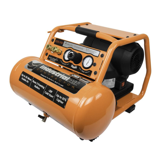
4-GALLON 225 PSI HIGH PERFORMANCE
CREW COMPRESSOR
Questions, problems, missing parts? Before returning to the store, call Customer Service
8 a.m. - 6 p.m., EST, Monday - Friday
PRODUCT SERVICE:
888-895-4549
industrialaircontractor.com
MODEL # C041I
MFG CSA FILE # U3A2257I
Type # 01
Advertisement
Table of Contents

Subscribe to Our Youtube Channel
Related Manuals for Industrial Air Contractor C041I


Summary of Contents for Industrial Air Contractor C041I
- Page 1 MODEL # C041I MFG CSA FILE # U3A2257I Type # 01 OPERATOR-PARTS MANUAL 4-GALLON 225 PSI HIGH PERFORMANCE CREW COMPRESSOR Questions, problems, missing parts? Before returning to the store, call Customer Service 8 a.m. - 6 p.m., EST, Monday - Friday...
-
Page 2: Table Of Contents
Table of Contents Safety Information ........2 System Components ......9 Work Area Safety ........2 Placement of the Air Compressor ..10 Personal Safety ........3 Attaching the Hose ......11 Moving the Compressor ......3 Tool Usage..........12 Air Compressor and Operation..........13 Pneumatic Tool Safety ......4 Maintenance ...........17 Electrical Safety ........5 General Maintenance ......17... -
Page 3: Personal Safety
Safety Information (continued) PERSONAL SAFETY WARNING: Stay alert when operating a power tool. Do not □ Keep proper footing and balance at all times. use the tool while tired or under the influence of drugs, Proper footing and balance enables better control alcohol, or medication. -
Page 4: Air Compressor And Pneumatic Tool Safety
Safety Information (continued) AIR COMPRESSOR AND WARNING: Do not attempt to modify this tool or create PNEUMATIC TOOL SAFETY accessories not recommended for use with this tool. Any such alteration or modification is misuse and could □ Keep compressors as far from the spraying area as result in a hazardous condition leading to possible serious personal injury. -
Page 5: Electrical Safety
Safety Information (continued) ELECTRICAL SAFETY (EXTENSION CORDS) WARNING: When using an extension cord, keep it clear of the working area. Position the cord so that it will not get □ Use only 3-wire extension cords that have 3-prong caught on lumber, tools, or other obstructions while you grounding plugs and 3-port grounded receptacles are working with a power tool. - Page 6 Safety Information (continued) ELECTRICAL SAFETY (SPEED AND WIRING) □ The no-load speed of this product is approximately 1,700 rpm. This speed is not constant and decreases under a load or with lower voltage. □ For voltage, the wiring in a shop is as important as the motor’s horsepower rating.
-
Page 7: Warranty
Warranty TWO YEAR LIMITED WARRANTY What Does This Warranty Cover? MAT Industries, LLC. (the Company) warrants from the date of purchase by the original retail purchaser only, parts and labor to remedy substantial defects found in materials, or workmanship. How Long Does The Coverage Last? The duration of this warranty is Two Years. This warranty is not transferable to subsequent owners. -
Page 8: Pre-Operation
Pre-Operation SPECIFICATIONS Running horsepower 1.7 HP Air tank capacity 4 gal. Air pressure 225 psi max. 6.8 SCFM at 40 psi Air delivery 5.0 SCFM at 90 psi Tank fill time 1.75 minutes Lubrication Oil free 120V, 60 Hz, Single phase Input AC only, 15 Amps. -
Page 9: System Components
Pre-Operation (continued) SYSTEM COMPONENTS Part Description ON ( I )/OFF ( 0 ) Switch: Turn this switch in the “ON ( I )” position to provide automatic power to the pressure switch and “OFF ( O )” to remove power at the end of each use. Safety Valve: If the pressure switch does not shut off the air compressor at its “cut-out”... -
Page 10: Placement Of The Air Compressor
Pre-Operation (continued) PLACEMENT OF THE AIR COMPRESSOR WARNING: If any parts are damaged or missing do not operate this product until the parts are replaced. Failure to heed this warning could result in serious personal injury. CAUTION: Do not use in an environment that is dusty or otherwise contaminated. -
Page 11: Attaching The Hose
Pre-Operation (continued) ATTACHING THE HOSE WARNING: Do not attempt to modify this product or create accessories not recommended for use with this product. Any such alteration or modification is misuse and could result in a hazardous condition leading to possible serious personal injury. WARNING: Do not attach the air chuck or other tools to the open end of the hose until start-up has been completed. -
Page 12: Tool Usage
Pre-Operation (continued) TOOL USAGE = Continuous = Intermittent = Not Recommended Framing/ Inflation Finishing Nailing Bolting Roofing Tool Brad Framing/Roofing Impact Heavy Duty 1/2 in. Inflator Stapler Air Ratchet Nailer Nailer Wrench and 3/4 in. Impact Wrench Recommended Tool Use HVLP Grease Cutting/Drilling... -
Page 13: Operation
Operation Preparing for start-up WARNING: Risk of unsafe operation. Firmly grasp air hose in hand when installing or disconnecting to prevent hose whip. WARNING: Risk of unsafe operation. Do not use damaged or worn accessories. WARNING: Risk of bursting. Too much air pressure causes a hazardous risk of bursting. - Page 14 Operation (continued) Starting the compressor WARNING: Risk of bursting. If any unusual noise or vibration is noticed, stop the air compressor immediately and have it checked by a trained service technician. NOTE: When using the regulator and other accessories, refer to the manufacturer’s instructions. □...
- Page 15 Operation (continued) Running the air compressor WARNING: Always ensure the switch is in the OFF position and regulator pressure gauge reads zero before changing air tools or disconnecting the hose from the air outlet. Failure to do so could result in possible serious personal injury.
- Page 16 Operation (continued) Draining the tank WARNING: Risk of unsafe operation. Air tanks contain high pressure air. Keep face and other body parts away from the drain outlet. Use eye protection [ANSI Z87.1 (CAN/ CSA Z94.3)] when draining, as debris can be kicked up into the face.
-
Page 17: Maintenance
Maintenance GENERAL MAINTENANCE WARNING: When servicing, use only identical Industrial Air Contractor replacement parts. Use of any other parts □ Condensation forms in the tank when may create a hazard or cause product damage. there is humidity in the air. Depending on the environmental conditions, drain the WARNING: Always release all pressure, disconnect from condensate daily and/or every hour. -
Page 18: Troubleshooting
Troubleshooting Problem Possible Cause Solution □ □ The compressor does not There is a loss of power or Check for proper use of extension cord. run. the motor is overheated. □ □ There is no power to the Check to be sure the unit is plugged in. unit. - Page 19 Troubleshooting (continued) Problem Possible Cause Solution □ □ The thermal overload protector There is low voltage from Call an electrician. cuts out repeatedly. the power source. □ □ There is a lack of proper Move the compressor to a well-ventilated ventilation, or the room area.
-
Page 20: Service Parts
Service Parts C041I, AIR COMPRESSOR... - Page 21 Service Parts (continued) C041I, AIR COMPRESSOR Item Number Description Part Number Tank 4G, Painted E109736 Regulator Manifold Body E109738 Regulator Manifold Panel E109744 Handle Grip E109743 Outlet Tube E110327 Isolator, Set of 4 E109475 Safety Valve E107851 Pump Isolator, Set of 3...
- Page 22 Service Parts (continued) C041I, AIR COMPRESSOR Item Number Description Part Number Screw .250-20 X .50 E109129 Power Cord Holder E109472 Screw .250-20 X .75 E106611 Screw 10-24 X .563 E106614 Screw 10-14 T20 E106646 Tank Top Panel E109742 Label Warning...
- Page 23 Service Parts (continued) PUMP/MOTOR ASSEMBLY Item Number Description Part Number Pulley E106663 Belt E106664 E106665 Screw E106666 Flywheel E106667 Screw E106668 Screw, kit of 4 E106669 Valve Plate Kit E106670 Conrod Kit E106671 Head E109721 Brush Kit E109432 industrialaircontractor.com Please contact 1-888-895-4549 for further assistance.
- Page 24 Questions, problems, missing parts? Before returning to the store, call Customer Service 8 a.m. - 6 p.m., EST, Monday - Friday PRODUCT SERVICE: 888-895-4549 industrialaircontractor.com Retain this manual for future use. Document Number: E110335 12/01/2016...
Need help?
Do you have a question about the C041I and is the answer not in the manual?
Questions and answers