Table of Contents
Advertisement
Quick Links
INSTALLATION & OPERATION MANUAL
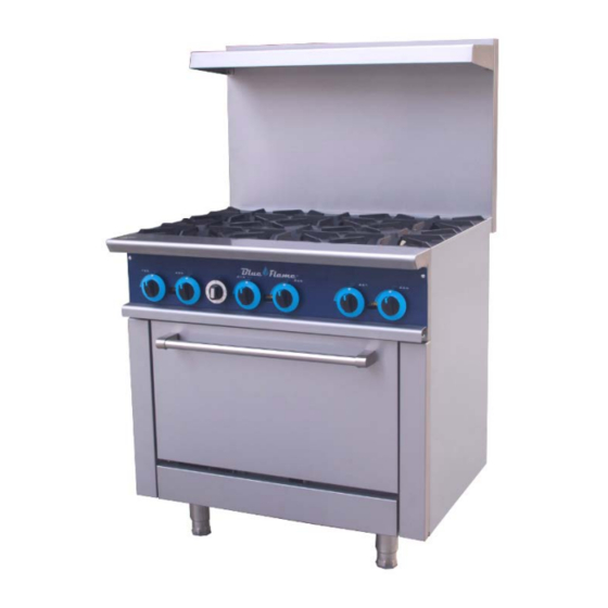
GAS RESTAURANT RANGES
Models: BFR-24-4, BFR-36-6, BFR-60-10, BFR-60-24G
BFR-60-24TG, BFR-60-24B
Blue Flame
223 W. Rosecrans Ave.
Gardena, CA. 90248 USA
Tel : 1.866.677.8500 / 1.310.808.0102
Fax : 1.310.808.0242 / 1.310.808.0262
WARNING: IMPROPER INSTALLATION, ADJUSTMENT, ALTERATION, SERVICE OR MAINTENANCE CAN
CAUSE PROPERTY DAMAGE, INJURY OR DEATH. READ THE INSTALLATION, OPERATING AND MAINTENANCE
INSTRUCTIONS THOROUGHLY BEFORE INSTALLING OR SERVICING THIS EQUIPMENT.
1
Advertisement
Table of Contents

Summary of Contents for Blue Flame BFR-24-4
- Page 1 INSTALLATION & OPERATION MANUAL GAS RESTAURANT RANGES Models: BFR-24-4, BFR-36-6, BFR-60-10, BFR-60-24G BFR-60-24TG, BFR-60-24B Blue Flame 223 W. Rosecrans Ave. Gardena, CA. 90248 USA Tel : 1.866.677.8500 / 1.310.808.0102 Fax : 1.310.808.0242 / 1.310.808.0262 WARNING: IMPROPER INSTALLATION, ADJUSTMENT, ALTERATION, SERVICE OR MAINTENANCE CAN CAUSE PROPERTY DAMAGE, INJURY OR DEATH.
-
Page 2: Important For Your Safety
IMPORTANT FOR YOUR SAFETY THIS MANUAL HAS BEEN PREPARED FOR PERSONNEL QUALIFIED TO INSTALL GAS EQUIPMENT, WHO SHOULD PERFORM THE INITIAL FIELD START-UP AND ADJUSTMENTS OF THE EQUIPMENT COVERED BY THIS MANUAL. POST IN A PROMINENT LOCATION THE INSTRUCTIONS TO BE FOLLOWED IN THE EVENT THE SMELL OF GAS IS DETECTED. - Page 3 Model List view Total Input Shipping Crated Model No. Description View Width BTU/hr Dimensions Weight Lbs/Kgs 153,000/NG BFR-24-4 4 top burner W27.5 X D36.6X 136,000/LP 366 / 166 range, one 24” H42.3 24” oven 213,000/NG 6 top burner W39.5 X D36.6X...
- Page 4 BLUE FLAME suggests that you thoroughly read this entire manual and carefully follow all of the instructions provided. THIS APPLIANCE IS EQUIPPED FOR NATURAL GAS, for conversion to LP gas please see gas conversion instruction manual attached.
-
Page 5: Installation Codes And Standards
INSTALLATION UNCRATING This range was inspected before leaving the factory. The transportation company assumes full responsibility for safe delivery upon acceptance of the shipment. Immediately after unpacking, check for possible shipping damage. If the range is found to be damaged, save the packaging material and contact the carrier within 15 days of delivery. - Page 6 Ranges must be installed in accordance with: In the United States of America: 1. State and local codes. 2. National Fuel Gas Code, ANSI/Z223.1 (latest edition). Copies may be obtained from The American Gas Association, Inc., 1515 Wilson Blvd., Arlington, VA22209. In Canada: 1.
- Page 7 Reconnect this restraint prior to turning the gas supply on and returning the range to its installation position. Separate instructions for installing casters to the range are included with the casters. Note: If the range is installed on casters and is moved for any reason, it is recommended that the range be leveled front to back and side to side.
- Page 8 shelf. Remove the backsplash components from the crating materials. Assemble the required components as shown in Fig’s. 2 and 3 and 4. Fig. 2 3. Tighten the four screws to secure the shelf. Fig. 3 Fig. 4 Lift the assembly up, sliding the channels into the space provided at the rear of the range.(Fig’s.
- Page 9 Fig. 5 5. Install four #10 sheet metal screws (2 to each channel leg) (Fig. 6). Fig.6 LEVELING Check the leveling of the range. Place a level inside the oven cavity across the...
-
Page 10: Gas Connections
oven rack(s). Level front-to-back and side-to-side. To adjust the leveling, tilt the range to one side and, using channel locks, unscrew the adjustable leg insert as required. Repeat this procedure as necessary for each leg. Optional casters for this range are of the non-adjustable type. Therefore, the floor must be level. -
Page 11: Testing The Gas Supply System
Fig. 7 The arrow on the regulator shows the direction of the gas flow. The pressure regulator must be mounted horizontally to ensure proper preset outlet pressure. If the regulator is installed in any other position, the outlet pressure must be reset for proper operation. -
Page 12: Operation
When gas supply pressure exceeds psig (3.45 kPa), the range and its individual shutoff valve must be disconnected from the gas supply piping system. When gas supply pressure is 1/ psig(3.45kPa) or less, the range should be isolated from the gas supply system by closing its individual manual shutoff valve until the range is ready for start-up. -
Page 13: Before First Use
CONTROLS THERMOSTAT DIAL Allows operator to regulate oven temperature from low to 500° F (260° C) (OPTIONAL) GRIDDLE BURNER KNOB Regulates gas flow to the griddle. To increase heat, turn knob counterclockwise, to decrease heat, turn knob clockwise. BEFORE FIRST USE optional models Griddle Seasoning ( CAUTION: This griddle plate is steel, but the surface is relatively soft and can be scored... - Page 14 1. Turn main gas supply ON. Wait 30 seconds and, using a long lighter, light the hot top or griddle top pilot 3. If pilot fails to light, turn main gas supply OFF. Wait 5 minutes and repeat the above procedures. 4.
-
Page 15: Open Top Burners
4. Press and hold red pilot button while lighting pilot. Once pilot is lit hold button for 30 seconds. 5. Release button. Pilot should remain on. 6. Close door. 7. If pilot fails to light, turn main gas supply OFF. Wait 5 minutes and repeat the above procedures. - Page 16 Complete Shutdown 1. Turn burner valve OFF; pilot will remain lit. 2. Turn main gas supply OFF. optional models GRIDDLE ( 1. Turn main gas supply ON. Wait 30 seconds and, using a taper, light broiler/griddle pilot. 2. If pilot fails to light, turn main gas supply OFF. Wait 5 minutes and repeat Steps 1 and 2.
-
Page 17: Rack Arrangement -Standard Oven
1. Turn burner valve OFF; pilot will remain lit. Complete Shutdown 1. Turn burner valve OFF; pilot will remain lit. 2. Turn main gas supply OFF. STANDARD OVEN LIGHTING AND SHUTDOWN INSTRUCTIONS NOTE: Light open top/griddle pilots before lighting oven pilot. 1. -
Page 18: Maintenance
into place To remove rack, reverse the procedure above by raising rear of oven rack stop above runner and pulling rack forward. PREHEATING Standard Oven Turn thermostat control to the desired cooking temperature and preheat oven for 25 minutes. To save on gas consumption, do not operate oven at maximum heat when it is not necessary. -
Page 19: Troubleshooting Guide
When calling for service, the following information must be available: model number, serial number, manufacture date (MD) and voltage (optional models). We all recognize, however, that replacement parts and occasional professional service may be necessary to extend the useful life of this unit. When service is needed, contact a RANGE Authorized Service Agency, or your dealer. - Page 20 (“the products”) shall be free of defects in material or workmanship under normal and proper use and maintenance service as specified by BLUE FLAME Products and upon proper installation (not to exceed 120 days from date of original shipment) and start-up in accordance with the instruction manual supplied with the Product.
- Page 21 • Failure to clean and/or maintain Product as set forth in the owner/ user manual for the Product. All claims for labor or parts must be made through BLUE FLAME Products. The defective part, for which labor reimbursement is claimed, together with the service invoice, must be returned to the BLUE FLAME Products within fifteen days from the date of service to be eligible for labor and parts warranty coverage.
- Page 22 Range Conversion Kit Instructions Do not attempt gas conversion by yourself. Gas conversion of your unit is to be made by a certified/licensed technician. CONVERSION Instructions are for conversion from Natural Gas to Propane (L.P.) on MR-4-G & MR-6-G models. The conversion should be done before connecting the unit to the gas supply.
- Page 23 7. Remove the drop pan, unscrew nut of oven burner 8 .Incline the burner, expose orifice of oven 9. Replace the orifice fittings into the valve. 10, Screw out oven burner air shutter screw 11, Adjust oven burner air shutter from half open to full open.
- Page 24 Pictured is the plastic insert. Pull off insert from octagon cap and reverse the plastic insert position so that the L.P. position is L.P. Position of attached to the octagon cap head. insert. Regulator is now converted to L.P. 13.2, Regulator convert for MR-10-G, MR-6-GR24-G, MR-6-GR24T-G change the part from R500 Nat 3”-6”W.C to R500 LP 11”W.C.
Need help?
Do you have a question about the BFR-24-4 and is the answer not in the manual?
Questions and answers