
Related Manuals for PendoTECH PressureMAT PMAT1


Summary of Contents for PendoTECH PressureMAT PMAT1
- Page 1 PressureMAT™ System User Guide Model PMAT1 Model PMAT2 Model PMAT3 Model PMAT4A Model PMAT4R Revision 1 www.pendotech.com...
- Page 2 The information in this User Guide is believed to be accurate and reliable for use and operation of the control system, however, PendoTECH assumes no responsibility for the use of this product except for what is covered in the Limited Warranty and Terms and Condition of Sale.
-
Page 3: Table Of Contents
Cable for Pressure Inputs ....................... 22 APPENDIX A: PRODUCT WARRANTY ................. 23 APPENDIX B: PendoTECH Single Use Pressure Sensors ............24 APPENDIX C: Data Collection to a PC via WinWedge Software ..........25 APPENDIX D: Panel Mount of System ..................26 APPENDIX F: Pinch Valve Box Accessory (PDKT-PVE) ............ -
Page 4: Overview Of Pendotech Pressuremat
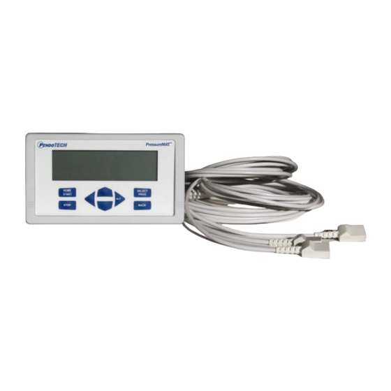
The PressureMAT is a monitor, alarm, and transmitter system designed for use with Single Use Pressure Sensors from PendoTECH. It is comprised of the control system box with user interface and the connectors on the back panel where input and output components can be interfaced. If equipped, the alarm output function includes a dry contact relay output. -
Page 5: Control System Details
PressureMAT User Guide Revision 1 The process pressure is displayed on the LCD display for each input channel. High and low alarm pressure set points are entered on the keypad for each channel and if the process pressure goes below the low setting or above the high setting, the system will go into alarm state. - Page 6 PressureMAT User Guide Revision 1 BACK PANEL CONFIGURATIONS: Two Input Unit (if two relays for each channel, 4-20mA will be labeled OUTPUT RELAY): Three Input Unit: Page 6/29...
- Page 7 PressureMAT User Guide Revision 1 Four Input Unit (4R shown, if 4A, OUTPUT RELAY is labeled OUTPUT 4-20mA): Page 7/29...
- Page 8 PressureMAT User Guide Revision 1 CONNECTIONS: The external connections to the back panel are as shown below. 1. POWER SUPPLY connected to the power inlet connector 2. The PRESSURE SENSOR INPUTS connected via the DB15 connector 3. The OUTPUT RELAY: a.
-
Page 9: Specifications
2.5 mm Circular Power Jack (center post positive) 12-24 Volts DC 4 Watts (powered by supplied appropriate wall supply) Pressure Sensor Inputs Configured for PendoTECH Single Use Pressure Sensors* (See Appendix B) Connector on reusable cable: DB15 Excitation voltage: 4.096V +/- 0.1% Relay Output Specifications for relay used for the alarm output: •... -
Page 10: Software Details
PressureMAT User Guide Revision 1 1.2.3. Software Details The software interface consists of the keypad (shown below) and the 8 line LCD backlit display. The program/firmware is stored in memory in the control system and cannot be edited by users. Only settings in the software menus can be changed. The system does not store any data. - Page 11 PressureMAT User Guide Revision 1 Keypad Function HOME/START Dual Purpose: 1- Used to return to the HOME screen from the program menus 2- Used to power on the system if turned off STOP Used to reset alarms (if optional alarm is latching turned On) LEFT ARROW Dual Purpose:...
- Page 12 PressureMAT User Guide Revision 1 Navigation Between Pressure Sensor Input Channels At the HOME screen, the UP/DOWN arrows are used to change the selected pressure input channel. Zero Calibration for Pressure Sensors 1. Select the desired input using the UP/DOWN buttons 2.
- Page 13 PressureMAT User Guide Revision 1 At the program menu, the BACK button may be pressed to return to the HOME screen or SELECT/PROG button pressed with the desired menu selected. The appearance and functions of the menus are as follows: Input Viewing At this screen the UP/DOWN arrows are used to select what value is displayed on the HOME screen.
- Page 14 PressureMAT User Guide Revision 1 Input Programming At this screen the UP/DOWN arrows are used to select what function to program. Press the SELECT/PROG button to program the function. The setting or digit of a setting that can be changed with the UP/DOWN arrows blinks. If there is more than one digit in a setting, use the RIGHT/LEFT arrows to scroll within the possible digit locations within a setting.
- Page 15 Serial Port. If Sio Report is selected, data is sent out the Serial RS232 port at the frequency programmed in the Global Settings Menu (contact PendoTECH for more details on data collection from the PressureMAT). Press the SELECT/PROG with Comm Port selected.
- Page 16 PressureMAT User Guide Revision 1 Output Programming At this screen the UP/DOWN arrows are used to select what function to program. The only function active is the Name. The Port Type can be selected and changed but no changes will be confirmed and will revert to the default setting.
- Page 17 PressureMAT User Guide Revision 1 Global Settings Menu The Global Settings menu can be used to program settings for the system that impacts all channels or turn ON or OFF features or view system information. To access the Global Settings menu press the BACK button three times in rapid succession. The following screen appears: GLOBAL SETTINGS >...
- Page 18 PressureMAT User Guide Revision 1 Alarm Latch If turned on, alarm conditions will remain after an alarm state occurred but is no longer present until the STOP button is pressed Backlight Can be set to High, Medium or Low Audio Beep Can be turned Off.
- Page 19 PressureMAT User Guide Revision 1 Next Report Indicates the next data report time. A report of the current system data is sent out the serial port with the RS232 protocol and can be captured into a PC program or other device.
-
Page 20: Using The System
PressureMAT User Guide Revision 1 2. Using the System 2.1. System Setup 1. Connect the pressure sensor cables to the back panel. If a pressure sensor is not connected when power is supplied to the system, the pressure will go to a value greater than 5.3 bar and an high pressure alarm condition will occur on the respective channel(s). -
Page 21: Using The System
PressureMAT User Guide Revision 1 2.2. Using the System 1. Using the instructions from the previous section 1.2.3, set the appropriate high and low alarm pressure settings for each channel. These are the set-points that will trigger an alarm condition. High and low pressure settings are entered on the key pad and if the process pressure goes below the low setting or above the high setting, the system will go into alarm state. -
Page 22: Cable Information
12 feet (3.7 m) in length with a 4 pin connector to connect a pressure sensor on one end and a male DB 15connector to connect to the control system on the other end (DB15 connector connected to PendoTECH Part Number PDKT-650-298) Wiring:... -
Page 23: Appendix A: Product Warranty
PressureMAT User Guide Revision 1 APPENDIX A: PRODUCT WARRANTY LIMITED WARRANTY: Except as otherwise expressly provided herein, Seller warrants that the Software will execute the programming instructions provided by Seller, and that the Goods manufactured by Seller will be free from defects in materials or workmanship under normal use and service until the expiration of the earlier of twelve (12) months from the date of initial installation or eighteen (18) months from the date of shipment by Seller. -
Page 24: Appendix B: Pendotech Single Use Pressure Sensors
Revision 1 APPENDIX B: PendoTECH Single Use Pressure Sensors PendoTECH’s Single Use Pressure Sensors are a low-cost solution for use with tubing and bioprocess containers and are compatible with both gamma and ETO sterilization. They can be integrated for pressure measurement and control. The sensors are designed for use with products offered by PendoTECH. -
Page 25: Appendix C: Data Collection To A Pc Via Winwedge Software
4. Install WinWedge software 5. Open WinWedge file attached called PressureMAT4.sw3 (this file is available from PendoTECH) 6. Select port / settings and select the COM port (if not sure of COM port number, Open PC Control... -
Page 26: Appendix D: Panel Mount Of System
PressureMAT User Guide Revision 1 APPENDIX D: Panel Mount of System PressureMAT All dimensions in inches, +/- 0.015 Page 26/29... - Page 27 Product Identification (brand models) PressureMAT Monitor, Alarm and Transmitter (PMAT1, PMAT2, PMAT3, PMAT4A, PMAT4R) with PendoTECH Single Use Pressure Sensors are in conformity with the provisions of the following EC Directive(s) when installed in accordance with the instructions contained in supplied product documentation:...
-
Page 28: Appendix F: Pinch Valve Box Accessory (Pdkt-Pve)
PressureMAT User Guide Revision 1 APPENDIX F: Pinch Valve Box Accessory (PDKT-PVE) Overview One to four pinch valves can be in each device. The cable to the associated PressureMAT relays must be wired the normally OPEN configuration (wired to S and T as shown in Section 1.2.1). The valves are normally closed and when there is NO POWER to the valve box or to the PressureMAT, the valves will be closed. - Page 29 PressureMAT User Guide Revision 1 Page 29/29...
Need help?
Do you have a question about the PressureMAT PMAT1 and is the answer not in the manual?
Questions and answers