Table of Contents
Advertisement
Quick Links
XR-C5100R/C5103R
SERVICE MANUAL
Cassette player section
Tape track
Wow and flutter
Frequency response
Signal-to-noise ratio
Tuner section
FM
Tuning range
Antenna terminal
Intermediate frequency
Usable sensitivity
Selectivity
Signal-to-noise ratio
Harmonic distortion at 1 kHz
Separation
Frequency response
Capture ratio
MICROFILM
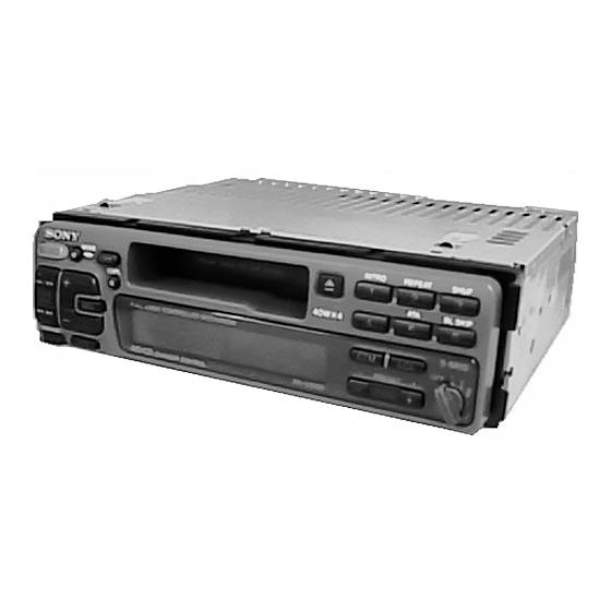
Photo: XR-C5103R
SPECIFICATIONS
4-track 2-channel stereo
0.08 % (WRMS)
30 – 18,000 Hz
TYPE II, IV
61 dB
TYPE I
58 dB
87.5 – 108.0 MHz
(XR-C5100R)
FM1, FM2: 87.5 – 108.0 MHz
FM3: 65.0 – 74.0 MHz
(XR-C5103R)
External antenna connector
10.7 MHz
8 dBf
75 dB at 400 kHz
65 dB (stereo), 68 dB (mono)
(XR-C5100R)
63 dB (stereo), 65 dB (mono)
(XR-C5103R)
0.5 % (stereo), 0.3 % (mono)
35 dB at 1 kHz
30 – 15,000 Hz
2 dB
East European Model
Model Name Using Similar Mechanism
Tape Transport Mechanism Type
MW/LW
Tuning range
Antenna terminal
Intermediate frequency
Sensitivity
Power amplifier section
Outputs
Speaker impedance
Maximum power output
General
Outputs
Tone controls
Power requirements
Dimensions
Mounting dimensions
Mass
Supplied accessories
Design and specifications are subject to change without notice.
FM/MW/LW CASSETTE CAR STEREO
AEP Model
UK Model
XR-C5100R
XR-C5103R
NEW
MG-25G-136
MW: 531 – 1,602 kHz
LW: 153 – 281 kHz
External antenna connector
10.71 MHz/450 kHz
MW: 30 µV
LW: 50 µV
Speaker outputs
(sure seal connectors)
4 – 8 ohms
40 W × 4 (at 4 ohms)
Telephone ATT control lead
Power amplifier control lead
Rear line out (1)
Bass ±8 dB at 100 Hz
Treble ±8 dB at 10 kHz
12 V DC car battery (negative ground)
Approx. 188 × 53 × 181 mm (w/h/d)
Approx. 182 × 53 × 164 mm (w/h/d)
Approx. 1.2 kg
Parts for installation and connections
(1 set)
Rotary commander RM-X4S
Front panel case (1)
Advertisement
Table of Contents

Related Manuals for Sony XR-C5103R


Summary of Contents for Sony XR-C5103R
- Page 1 XR-C5100R/C5103R SERVICE MANUAL AEP Model UK Model XR-C5100R East European Model XR-C5103R Photo: XR-C5103R Model Name Using Similar Mechanism Tape Transport Mechanism Type MG-25G-136 SPECIFICATIONS Cassette player section MW/LW Tape track 4-track 2-channel stereo Tuning range MW: 531 – 1,602 kHz Wow and flutter 0.08 % (WRMS)
-
Page 2: Table Of Contents
TABLE OF CONTENTS Flexible Circuit Board Repairing • Keep the temperature of the soldering iron around 270 ˚C dur- ing repairing. GENERAL • Do not touch the soldering iron on the same conductor of the Location of Controls ............3 circuit board (within 3 times). - Page 3 SECTION 1 This section is extracted from instruction manual. GENERAL – 3 –...
- Page 4 – 4 –...
- Page 5 – 5 –...
- Page 6 – 6 –...
- Page 7 – 7 –...
- Page 8 – 8 –...
-
Page 9: Disassembly
SECTION 2 DISASSEMBLY Note: Follow the disassembly procedure in the numerical order given. FRONT PANEL ASS’Y 1 Push the button (release). 2 Remove the front panel ass’y to the direction of the arrow A . COVER ASS’Y 3 cover ass’y –... - Page 10 5 screw SUB PANEL, MECHANISM DECK (MG-25G-136) (PTT2.6 × 6) 3 connector (CN352) 6 mechanism deck (MG-25G-136) 4 flexible flat cable (CN351) 2 sub panel 1 three screws (PTT2.6 × 8) 1 three screws (PTT2.6 × 8) MAIN BOARD, HEAT SINK 6 two screws (PTT2.6 ×...
-
Page 11: Assembly Of Mechanism Deck
SECTION 3 ASSEMBLY OF MECHANISM DECK Note: Follow the assembly procedure in the numerical order given. HOUSING 7 Holder the hanger by bending the claw. 5 Fit projection on C part. 1 Install the catch to the hanger. 2 Install the hanger onto two claws of the housing. - Page 12 LEVER (LDG-A) / (LDG-B) shaft A shaft A shaft B shaft B shaft C 1 Fit the lever (LDG-A) on shafts A – C and install it. 3 type-E stop ring 2.0 2 Fit the lever (LDG-B) on shafts A and B and install it.
- Page 13 GUIDE (C) 2 guide (C) 1 three claws – 13 –...
-
Page 14: Mechanical Adjustments
SECTION 4 SECTION 5 MECHANICAL ADJUSTMENTS ELECTRICAL ADJUSTMENTS 1. Clean the following parts with a denatured-alcohol-moistened TEST MODE swab: This set have the test mode function. In the test mode, FM Auto playback head pinch roller Scan/Stop Level and AM (MW) Auto Scan/Stop Level adjustments rubber belt capstan can be performed easier than it in ordinary procedure. -
Page 15: Tuner Section
FM Noise Focus Adjustment (XR-C5100R only) TUNER SECTION 0 dB=1µV Setting: [SOURCE] button: FM Cautions during repair When the tuner unit is defective, replace it by a new one be- FM RF signal cause its internal block is difficult to repair. level meter antenna jack (J1) generator... - Page 16 FM Signal Meter Adjustment AM (MW) Auto Scan/Stop Level Adjustment Setting: Make this adjustment after “FM Auto Scan/Stop Level Adjust- [SOURCE] ment”. button: FM Setting: FM RF signal [SOURCE] button: MW generator antenna jack (J1) 30 Ω 15 pF 0.01 µ F 65 pF Carrier frequency : 98.00 MHz : 35 dB (56.2 µ...
- Page 17 Adjustment Location: – SET UPPER VIEW – Tape Speed Adjustment RV1 AM (MW) Auto Scan/Stop Level Adjustment RV2 FM Auto Scan/Stop Level Adjustment RV3 FM Noise Focus Adjustment (XR-C5100R only) RV4 FM Stereo Separation Adjustment RV1 FM Signal Meter Adjustment –...
-
Page 21: 6-5. Ic Pin Function Description
6-5. IC PIN FUNCTION DESCRIPTION • MAIN BOARD IC501 MN1886426SA (XR-C5100R) (SYSTEM CONTROLLER) IC501 MN1886426SB (XR-C5103R) (SYSTEM CONTROLLER) Pin No. Pin Name Function TUNMUT FM audio signal muting control output terminal “H”: muting on AMPON Standby control signal output to the power amplifier (IC801) “L”: standby Power supply on/off control signal output terminal at the illumination and liquid crystal display driver (IC901) “H”: power on... - Page 22 Ground terminal (for A/D converter) — Ground terminal BUSON Bus on/off control signal output to the bus interface (IC701) (for SONY bus) “L”: bus on SYSRST Reset signal output to the bus interface (IC701) (for SONY bus) “L”: reset SEKOUT...
- Page 23 Pin No. Pin Name Function Input of FM stereo detection signal from FM/AM tuner unit (TU1), and output of forced monaural control signal to FM/AM tuner unit (TU1) (Commonly used for stereo display input ST IN and forced monaural output) FM stereo detection at input of “L”, forced monaural at output of “L”...
- Page 24 • IC Block Diagrams – MAIN Section – IC1 TB2114F (EL) 24 23 21 20 14 13 RIPPLE FILTER – – SEEK/RECP SEEK/RECP 4BIT SWALLOW MODULAS COUNTER PRESCALER 12BIT PHASE PROGRAMABLE COMPARATOR COUNTER REFERENCE 40BIT 18BIT 20BIT COUNTER 22BIT SHIFT IF COUNTER 18BIT RESISTER...
- Page 25 IC151 LC75373ED – LFIN – – – LFOUT – LSELO LROUT – – – VREF SHIFT DECODER LATCH CONTROL REGISTER – – – RROUT RSELO – RFOUT – – – – RFIN 6 7 8 9 10 IC351 CXA2509AQ-T4 IC360 MM1322XFBE 8 OUT2 24dB 120µ/70µ...
- Page 26 IC601 BA3918-V2 IC701 BA8270F-E2 BUS ON BUS ON SWITCH REGULATOR RESET SWITCH BUS ON CLK IN BATTERY BATT BU IN SWITCH OVER VOLTAGE PROTECT VREF – DATA DATA IN DATA OUT 2 3 4 • Waveforms – MAIN Section – 1 IC1 1 XO 2 IC3 9 XO 42 mVp-p...
-
Page 27: Exploded Views
1-782-092-11 CORD (WITH CONNECTOR) (ISO-P) (POWER) A-3313-463-A MAIN BOARD, COMPLETE 1-782-093-11 CORD (WITH CONNECTOR) (ISO-S) (SPEAKER) (XR-C5100R: German) 1-777-989-41 CORD (WITH CONNECTOR) (AMP REM/ATT) A-3313-475-A MAIN BOARD, COMPLETE (XR-C5103R) * 19 3-019-148-01 BRACKET (HS) (M) 3-915-923-01 SCREW, GROUND POINT X-3373-269-1 COVER ASSY (ISO) - Page 28 3-018-612-01 PLATE, LIGHT GUIDE X-3374-680-1 PANEL SUB ASSY (XR-C5100R) * 117 3-018-611-01 HOLDER (LCD) X-3374-681-1 PANEL SUB ASSY (XR-C5103R) 3-009-295-01 PANEL, FRONT BACK 3-009-300-01 BUTTON (SOURCE) 3-904-194-01 EMBLEM (NO. 2.5), SONY 3-009-297-01 BUTTON (L) (r. OFF. + +). SEEK AMS.
- Page 29 (3) MECHANISM DECK SECTION (MG-25G-136) HP901 M901 Ref. No. Part No. Description Remark Ref. No. Part No. Description Remark A-3291-667-A CLUTCH (FR) ASSY 3-933-346-01 CATCHER * 152 3-019-130-01 LEVER (LDG-A) 3-933-344-01 GUIDE (C) * 153 3-019-131-01 LEVER (LDG-B) 3-014-798-01 SCREW (HEAD), SPECIAL 3-020-539-01 SPRING (LD-1), TENSION 3-364-151-01 WASHER 3-020-540-01 SPRING (LD-2), TENSION...
-
Page 30: Electrical Parts List
SECTION 8 ELECTRICAL PARTS LIST NOTE: When indicating parts by reference • Due to standardization, replacements in the • Items marked “*” are not stocked since they number, please include the board. parts list may be different from the parts speci- are seldom required for routine service. - Page 31 10uF (XR-C5100R:AEP, UK, South European) C119 1-126-157-11 ELECT 10uF A-3313-463-A MAIN BOARD, COMPLETE C120 1-126-157-11 ELECT 10uF (XR-C5100R: German) A-3313-475-A MAIN BOARD, COMPLETE (XR-C5103R) C121 1-126-157-11 ELECT 10uF C122 1-163-251-11 CERAMIC CHIP 100PF ********************* (Including POWER BOARD, COMPLETE) C123 1-163-251-11 CERAMIC CHIP...
- Page 32 MAIN Ref. No. Part No. Description Remark Ref. No. Part No. Description Remark C211 1-126-160-11 ELECT C612 1-109-982-11 CERAMIC CHIP C212 1-164-182-11 CERAMIC CHIP 0.0033uF 10% C614 1-163-251-11 CERAMIC CHIP 100PF C615 1-163-251-11 CERAMIC CHIP 100PF C213 1-109-982-11 CERAMIC CHIP C617 1-126-157-11 ELECT 10uF...
- Page 33 1-216-296-00 SHORT (CHIP) 0 JC70 1-216-296-00 SHORT (CHIP) 0 IC501 8-759-492-39 IC MN1886426SA (XR-C5100R) JC71 1-216-296-00 SHORT (CHIP) 0 IC501 8-759-492-41 IC MN1886426SB (XR-C5103R) JC72 1-216-296-00 SHORT (CHIP) 0 IC571 8-759-363-81 IC XC61AN4002PR JC73 1-216-296-00 SHORT (CHIP) 0 IC601 8-759-347-49 IC BA3918-V2...
- Page 34 1-216-041-00 METAL CHIP 1/10W (XR-C5100R: German) R537 1-216-699-11 METAL CHIP 100K 0.5% 1/10W R208 1-216-065-00 METAL CHIP 4.7K 1/10W (XR-C5103R) R209 1-216-065-00 METAL CHIP 4.7K 1/10W R538 1-216-246-00 RES, CHIP 100K 1/8W R210 1-216-089-00 RES, CHIP 1/10W (XR-C5100R: AEP, UK, South European,...
- Page 35 1-416-046-11 INDUCTOR 400uH 1-693-373-11 TUNER UNIT FAE338-A01 (FM/AM) < RESISTOR > (XR-C5100R) A-3282-031-A TUNER UNIT TUX-006/2 (EE) (FM/AM) R801 1-216-198-00 RES, CHIP 1/8W (XR-C5103R) R802 1-216-198-00 RES, CHIP 1/8W R803 1-216-049-11 RES, CHIP 1/10W < VIBRATOR > R804 1-216-049-11 RES, CHIP 1/10W 1-567-848-11 VIBRATOR, CRYSTAL (7.2MHz)
- Page 36 (XR-C5100R: AEP, German) 3-861-722-31 MANUAL, INSTRUCTION, INSTALL (POLISH, TURKISH, CZECH, GREEK, ENGLISH) (XR-C5100R: South European) 3-861-729-11 MANUAL, INSTRUCTION (RUSSIAN, HUNGARIAN) (XR-C5103R) 3-861-730-11 MANUAL, INSTRUCTION, INSTALL (RUSSIAN, HUNGARIAN) (XR-C5103R) 3-861-973-11 MANUAL, INSTRUCTION, INSTALL (for RM-X4S) (ENGLISH, FRENCH, GERMAN, SPANISH, DUTCH, SWEDISH, ITALIAN,...
Need help?
Do you have a question about the XR-C5103R and is the answer not in the manual?
Questions and answers