Table of Contents
Advertisement
Quick Links
Advertisement
Table of Contents

Summary of Contents for multicomp MP7505 Series
- Page 1 MP7505 Series Dual-Channel Arbitrary Waveform Generator User Manual...
-
Page 2: Table Of Contents
Table of Contents 1.General Safety Requirement ..............1 2.Safety Terms and Symbols ..............2 3.General Inspection ................3 4.Quick Start .................... 4 Front Panel Overview ........................ 4 Rear Panel Overview ......................... 6 Foot Stool Adjustment ......................7 Power On ........................... 7 User Interface .......................... - Page 3 Output the Modulated Waves ....................25 AM (Amplitude Modulation) ................... 26 DSB-AM (Double-Sideband AM) ..................27 FM (Frequency Modulation) ................... 28 PM (Phase Modulation) ....................30 PWM (Pulse Width Modulation) ..................31 ASK (Amplitude Shift Keying) ..................32 FSK (Frequency Shift Keying) ................... 34 PSK (Phase Shift Keying) ....................
- Page 4 Preset Settings (Preset) ......................58 Restore to the factory setting ..................59 Restore to the user setting ....................63 Power-on setting ......................63 Use Build-in Help (Help) ......................63 6.Communicate with PC ................. 64 Using USB Port......................... 64 Using LAN Port ........................65 Connect Directly ......................
-
Page 5: General Safety Requirement
MP7505 Series User Manual 1. General Safety Requirement Before any operations, please read the following safety precautions to avoid any possible bodily injury and prevent this product or any other products connected from damage. In order to avoid any contingent danger, this product must only be used within the ranges specified. -
Page 6: Safety Terms And Symbols
MP7505 Series User Manual 2. Safety Terms and Symbols Safety Terms Terms in this Manual. The following terms may appear in this manual: Warning: Warning indicates the conditions or practices that could result in injury or loss of life. Caution: Caution indicates the conditions or practices that could result in damage to this product or other property. -
Page 7: General Inspection
If there is any accessory lost or damaged, please get in touch with the distributor of MULTICOMP PRO responsible for this service or the MULTICOMP PRO's local offices. -
Page 8: Quick Start
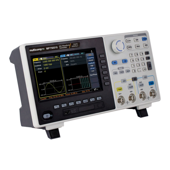
MP7505 Series User Manual 4. Quick Start Front Panel Overview Figure 4-1: Front Panel overview Display the user interface Menu selection Includes 6 keys to activate the corresponding menu keys Mode keys Mod: Output the modulated waveform Sweep: Scan the sine, square, ramp or arbitrary waveforms... - Page 9 MP7505 Series User Manual Direction key Move the cursor of the selected parameter Operation keys Counter: Enter the counter interface Edit: Enter the wavform edit interface Preset: Enter the preset menu, set the reset parameter or power-on parameter. Utility: Set the utility function...
-
Page 10: Rear Panel Overview
MP7505 Series User Manual Yellow Trigger button: CH1 manual trigger button. In sweep or burst mode, when the trigger source is selected as “Manual”, each press of this button will initiate a trigger. On/Off button: Turns the output of the CH1 channel on or off. -
Page 11: Foot Stool Adjustment
MP7505 Series User Manual Foot Stool Tilt the signal generator for easy operation. LAN interface The network port, which can be used to connect with a PC. USB Device interface Used to connect a USB type B controller. Can be connected with PC, so the signal generator can be controlled by the host computer software. -
Page 12: User Interface
MP7505 Series User Manual User Interface Figure 4-3: User Interface 1 Display channel name and channel switch status 2 Current waveform or current mode 3 Trigger source Internal: Internal modulation or internal trigger source External: External modulation or external trigger source... -
Page 13: Panel Operation
MP7505 Series User Manual 5. Panel Operation Channel Setting Select the channel for configuration Before configuring waveform parameters, you must select the channel you want to configure. Press CH1 or CH2 to select the corresponding channel, and the corresponding channel area in the user interface will light up. -
Page 14: Output Sine Wave
MP7505 Series User Manual the parameters that can be set are different. Note: The following setting waveform uses CH1 channel as an example. If you need to set CH2 channel, please refer to CH1 channel specific operation. Output Sine Wave Press , the screen displays the user interface of the sine wave. -
Page 15: Set The Amplitude
MP7505 Series User Manual press the Enter key to confirm the input in default unit. Press the MHz, kHz, Hz, mHz, uHz softkeys to select the unit of the parameter. Press the Cancel softkey to cancel the current input parameter value. -
Page 16: Set The Low Level
MP7505 Series User Manual Set the low level Press the Offset/Low softkey to confirm whether the Low menu item is highlit; if not, press the Offset/Low softkey to switch to Low. In Parameter 3 of Figure 5-1, a blinking cursor appears in the parameter value of low level. Turn the rotary control to change the value directly, or use the numeric keypad to input the desired value and choose the unit. -
Page 17: Set The Symmetry
MP7505 Series User Manual Level, Start Phase, and Symmetry. To set the Frequency/Period, Amplitude/High Level, Offset/Low Level, Start Phase, please refer to Output Sine Wave on page 10. Figure 5-4: Ramp wave user interface Set the symmetry Press the Symmetry softkey, the Symmetry menu item is highlit. In Parameter 5 of Figure 5-4, a blinking cursor appears in the parameter value of symmetry. -
Page 18: Output Pulse Wave
MP7505 Series User Manual Glossary Symmetry: Sets the percentage of the period during which the ramp waveform is rising. Output Pulse Wave Press , the screen displays the user interface of the pulse wave. The Pulse waveform parameters can be set by operating the Pulse setting menu on the right. -
Page 19: Set The Pulse Width/Duty Cycle
MP7505 Series User Manual Set the pulse width/duty cycle Press the Width/DutyCyc softkey, the chosen menu item is highlit. Press the Width/DutyCyc softkey to switch between Pulse Width and Duty Cycle. In Parameter 5 of Figure 5-6, a blinking cursor appears in the parameter value. Turn the rotary control to change the value directly, or use the numeric keypad to input the desired value and choose the unit. - Page 20 MP7505 Series User Manual Glossary Pulse Width PW is an abbreviation for pulse width and is divided into positive pulse width and negative pulse width. The positive pulse width is the time interval from 50% of the rising edge to 50% of the adjacent falling edge.
-
Page 21: Set The Rising/Falling Time
MP7505 Series User Manual Set the rising/falling time Press the Rising/Falling softkey, the chosen menu item is highlit. Press the Rising/Falling softkey to switch between Rising Time and Falling Time. In Parameter 6 of Figure 5-6, a blinking cursor appears in the parameter value. Turn the rotary control to change the value directly, or use the numeric keypad to input the desired value and choose the unit. -
Page 22: Select Build-In Wave (Including Dc)
MP7505 Series User Manual The arbitrary wave menu includes: Frequency/Period, Amplitude/High Level, Offset/Low Level, Start Phase, and Built-in Waveform. To set the Frequency/Period, Amplitude/High Level, Offset/Low Level, Start Phase, please refer to Output Sine Wave on page 10. The Arbitrary signal consists of two types: the system built-in waveform and the user-definable waveform. - Page 23 MP7505 Series User Manual (3) Turn the rotary control to select the desired waveform, for example, select AbsSine. Press the OK softkey to enter the Airy function. Note: DC is a type of built-in waveform, located in the Common type, named "DC".
- Page 24 MP7505 Series User Manual Standard Ignition Automobile internal combustion engine ignition waveform TP2A Automotive transients due to inductance in the wiring Automobile starting profile with oscillation Working voltage profile of the car when resetting Automotive transients due to power cuts...
- Page 25 MP7505 Series User Manual Trigonometric function CosH Hyperbolic cosine Cotangent function CotH Hyperbolic cotangent CotHCon Concave hyperbolic cotangent CotHPro Raised hyperbolic cotangent CscCon Recessed cosecant Cosecant CscPro Raised cosecant CscH Hyperbolic cosecant CscHCon Depressed hyperbolic cosecant CscHPro Raised hyperbolic cosecant...
- Page 26 MP7505 Series User Manual ATanH Inverse hyperbolic tangent function Window function Bartlett Bartlett window BarthannWin Modified Bartlett window Blackman Blackman window BlackmanH BlackmanH window BohmanWin BohmanWin window Boxcar Rectangular window ChebWin Chebyshev window FlattopWin Flat top window Hamming Hamming window...
-
Page 27: Output Harmonic Wave
MP7505 Series User Manual Segement Modulation Sinusoidal segmented AM wave Sinusoidal segmented FM wave Sinusoidal segmented PM wave Pulse width segmented PWM wave Fan test 64n/1024 Order adjustment (n is an integer, the range is 0 - 16) Output Harmonic Wave... -
Page 28: Set The Fundamental Wave Parameters
MP7505 Series User Manual the fundamental frequency is called an even harmonic. This waveform generator can output up to 16th order of harmonic. After selecting Harmonic wave button to enter the harmonic setting CH1 or CH2, press the menu. You can set the parameters of the fundamental waveform, select the type of harmonic, specify the highest order of harmonic, and set the amplitude and phase of each order of harmonic. -
Page 29: Set The Harmonic Amplitude Of Each Order
MP7505 Series User Manual next page, and press the Order softkey, the Order menu item is highlit. In Parameter 5 of Figure 5-10, a blinking cursor appears in the parameter value of order. Turn the rotary control to change the value directly, or use the numeric keypad to input the desired value, which can be set from 2 to 16. -
Page 30: Am (Amplitude Modulation)
MP7505 Series User Manual AM (Amplitude Modulation) The modulated waveform consists of the carrier wave and the modulating wave. For AM, the amplitude of the carrier wave varies with the instantaneous voltage of the modulating wave. The AM user interface is shown below. -
Page 31: Dsb-Am (Double-Sideband Am)
MP7505 Series User Manual (6) Set modulating wave frequency: Press the AM Frequency softkey to set the modulating wave frequency. The range is 2 mHz – 1 MHz (for internal source only). (7) Set modulation depth: Press the Depth softkey to set the modulation depth. The range is 0% - 120%. -
Page 32: Fm (Frequency Modulation)
MP7505 Series User Manual How to set the parameters of DSB-AM (1) Press the Mod function key, then press the Type softkey, turn the rotary control to select DSBAM, press the OK softkey. (2) Select carrier wave shape: The carrier wave can be Sine, Square, or Ramp. Press , or select a desired carrier wave shap. - Page 33 MP7505 Series User Manual Figure 5-13: FM user interface How to set the parameters of FM (1) Press the Mod function key, then press the Type softkey, turn the rotary control to select FM, press the OK softkey. (2) Select carrier wave shape: The carrier wave can be Sine, Square, Ramp, or Arbitrary wave (except DC).
-
Page 34: Pm (Phase Modulation)
MP7505 Series User Manual (7) Set frequency deviation: Frequency deviation is the deviation of the modulating wave frequency relative to the carrier wave frequency. Press the Deviation softkey to set the FM frequency deviation. Frequency deviation range: 2 mHz ≤ deviation < upper limit (upper limit is carrier frequency or carrier maximum frequency minus carrier frequency, the smaller of the two). -
Page 35: Pwm (Pulse Width Modulation)
MP7505 Series User Manual (4) Select modulating wave source: Press the Source softkey to select the modulating wave source. If you select External, use the Mod/FSK/Trig connector at the rear panel to input the external modulating signal, then skip ahead to step (7). -
Page 36: Ask (Amplitude Shift Keying)
MP7505 Series User Manual How to set the parameters of PWM (1) Set carrier wave shape: PWM can only be used to modulate pulse, so the carrier wave must be Pulse. Press to set the carrier wave shap. (2) Press the Mod function key, then press the Type softkey, turn the rotary control to select PWM, press the OK softkey. - Page 37 MP7505 Series User Manual Figure 5-16: ASK user interface How to set the parameters of ASK (1) Press the Mod function key, then press the Type softkey, turn the rotary control to select ASK, press the OK softkey. (2) Select carrier wave shape: The carrier wave can be Sine, Square, Ramp, or Arbitrary wave (except DC).
-
Page 38: Fsk (Frequency Shift Keying)
MP7505 Series User Manual low level. The situation is the opposite when the slope is set to Negative. (6) Set modulating amplitude: Press the Amplitude softkey to set the modulating amplitude. FSK (Frequency Shift Keying) Frequency Shift Keying modulation is a modulation technique that shifts the output signal frequency between two frequencies: the carrier frequency and hop frequency. -
Page 39: Psk (Phase Shift Keying)
MP7505 Series User Manual (5) If you select Internal, the modulating wave is set as a Square with 50% duty cycle. Press the FSK Rate softkey to set the FSK rate. The rate at which the output frequency shifts between the carrier frequency and the hop frequency is determined by FSK rate (for internal source only). -
Page 40: 3Fsk (3 Frequency Shift Keying)
MP7505 Series User Manual How to set the parameters of PSK (1) Press the Mod function key, then press the Type softkey, turn the rotary control to select PSK, press the OK softkey. (2) Select carrier wave shape: The carrier wave can be Sine, Square, Ramp, or Arbitrary wave (except DC). - Page 41 MP7505 Series User Manual Figure 5-19: 3FSK user interface How to set the parameters of 3FSK (1) Press the Mod function key, then press the Type softkey, turn the rotary control to select 3FSK, press the OK softkey. (2) Select carrier wave shape: The carrier wave can be Sine, Square, Ramp, or Arbitrary wave (except DC).
-
Page 42: 4Fsk (4 Frequency Shift Keying)
MP7505 Series User Manual 4FSK (4 Frequency Shift Keying) 4 Frequency Shift Keying modulation is a modulation technique that shifts the output signal frequency among four preset frequencies: the carrier frequency and three hop frequencies. The shift frequency (4FSK rate) is determined by the internal signal level of the instrument. -
Page 43: Bpsk (Binary Phase Shift Keying)
MP7505 Series User Manual (5) Set 4FSK rate: Press the FSK Rate softkey to set the 4FSK rate. The rate at which the output frequency shifts between the carrier frequency and the three hop frequencies is determined by 4FSK rate (for internal source). The range is 2 mHz – 1 MHz. -
Page 44: Qpsk (Quadrature Phase Shift Keying)
MP7505 Series User Manual (3) Set carrier wave parameters: Press the wave shap key of the selected carrier wave to display the waveform and parameters of the carrier wave. You can change the parameters of the carrier wave. Press Mod to return to the modulation mode interface. -
Page 45: Osk (Oscillation Shift Keying)
MP7505 Series User Manual How to set the parameters of QPSK (1) Press the Mod function key, then press the Type softkey, turn the rotary control to select QPSK, press the OK softkey. (2) Select carrier wave shape: The carrier wave can be Sine, Square, Ramp, or Arbitrary wave (except DC). - Page 46 MP7505 Series User Manual Figure 5-23: OSK user interface How to set the parameters of OSK (1) Set carrier wave shape: OSK carrier wave can only be sine wave. Press to set the carrier wave shap. (2) Press the Mod function key, then press the Type softkey, turn the rotary control to select OSK, press the OK softkey.
-
Page 47: Sum (Sum Modulation)
MP7505 Series User Manual SUM (Sum Modulation) The modulated waveform consists of the carrier wave and the modulating wave. For SUM, the amplitude of the carrier wave varies with the instantaneous voltage of the modulating wave. The SUM user interface is shown below. -
Page 48: Generate Sweep (Sweep)
MP7505 Series User Manual (6) Set modulating wave frequency: Press the AM Frequency softkey to set the modulating wave frequency. The range is 2 mHz – 1 MHz (for internal source only). (7) Set modulation depth: Press the Depth softkey to set the modulation depth. The range is 0% - 100%. -
Page 49: Generate Burst (Burst)
MP7505 Series User Manual (4) Press the Type softkey to switch the sweep type. When Linear is selected, the output frequency of the instrument varies linearly during the sweep. When Log is selected, the output frequency of the instrument varies in a logarithmic fashion during the sweep. -
Page 50: Set N-Cycle Burst
MP7505 Series User Manual Glossary Burst: The set of pulses transmitted together is called a "burst". The various signal generators are commonly referred to as the BURST function. N cycle burst: Contains a specific number of waveform cycles, each of which is initiated by a trigger event. -
Page 51: Set Gated Burst
MP7505 Series User Manual Note: Before configuring the waveform parameters, you must first select the channel you want to configure. Press CH1 or CH2 to select the corresponding channel, and the corresponding channel area in the user interface will light up. - Page 52 MP7505 Series User Manual support gated burst are Sine, Square, Ramp, Pulse, Noise and Arbitrary waveforms (except DC). Figure 5-27: Gated burst user interface (1) When the output signal is Sine, Square, Ramp, Pulse, Noise or Arbitrary wave (except DC), press the front panel Burst function key to enter the burst mode (the backlight of the key lights up).
-
Page 53: Counter
MP7505 Series User Manual Counter The frequency counter measures signals in the frequency range from 100 mHz to 200 MHz. The 10MHz In/Out/Counter connector on the rear panel is used by default to receive the frequency counter input signal. The frequency meter works from the start, unless the connector is set to an external clock input or clock output. -
Page 54: Utility Function Setting
MP7505 Series User Manual Utility Function Setting Press the front panel Utility function key to enter the utility menu. You can set the parameters of the generator such as: display settings, CH1/2 settings, I/O setup, and system settings. Press Utility again to exit the utility menu. -
Page 55: Date
MP7505 Series User Manual Date (1) Press the front panel Utility function key, press the Display softkey. (2) Press the Date softkey to select Date. (3) Turn the rotary control to adjust the value on the current cursor, use the direction key to move cursor left or right, or use the numeric keypad to enter the value. -
Page 56: Load
MP7505 Series User Manual wave with a 50% duty cycle. In the first half of the modulation waveform, the sync signal is TTL high. When external modulation is performed, there is no sync signal output. For ASK, FSK, PSK, BPSK, QPSK, 3FSK, 4FSK, the synchronization signal is referenced to the keying frequency, and the synchronization signal is a square wave with a duty cycle of 50%. -
Page 57: Usb Device Type
MP7505 Series User Manual USB Device Type The user can set the communication protocol type of the USB Device interface at the rear panel. (1) Press the front panel Utility function key, press the I/O Setup softkey. (2) Press the USBDEV softkey to toggle between PC and USBTMC. -
Page 58: System Settings
MP7505 Series User Manual System Settings Language (1) Press the front panel Utility function key, press the System softkey. (2) Press the Language softkey to switch the display language. Beeper When the beeper is turned on, the beeper sounds when users operate the front panel or when an error occurs. -
Page 59: Firmware Update
MP7505 Series User Manual Firmware Update (1) Press the front panel Utility function key, press the System softkey. (2) Plug the USB storage device into the USB connector on the front panel of the instrument. Note: If the USB storage device is not inserted, the Update firmware menu is disabled. -
Page 60: File Store System (Store)
MP7505 Series User Manual Repeat this step to set all the points. Press Write to enter the file system interface. If you want to save the waveform to the internal memory, select INTER and press Enter softkey. Turn the rotary control to select one of the USER files (EditMemory cannot be selected) and press the Save softkey. -
Page 61: Bring Up Arbitrary Wave Files In Internal/External Memory
MP7505 Series User Manual select INTER and press the Arb file softkey. Turn the rotary control to select one of the USER files (EditMemory cannot be selected) and press the Save softkey. (The file size is displayed on the right side of the USER file. If 0B is displayed, it means the file is empty.) -
Page 62: Erase Waveforms From Memory
MP7505 Series User Manual To copy the waveform file from the USB storage device to internal memory: After the waveform file in the USB storage device is called up according to the previous step, press the Back softkey to return to the upper directory. After returning to the memory selection interface, turn the rotary control to select INTER and press the Arb file softkey. -
Page 63: Restore To The Factory Setting
MP7505 Series User Manual Restore to the factory setting (1) Press the front panel Preset function key to enter the preset menu. (2) Press the ResetSet softkey to select Factory. (3) Press the Reset softkey, and then press the OK softkey to restore the generator to the factory default settings. - Page 64 MP7505 Series User Manual Modulation Waveform Factory Setting Modulation type Modulating Waveform Sine AM Frequency 100 Hz Modulation Depth 100% Modulation Source Internal Modulating Waveform Sine FM Frequency 100 Hz Frequency Deviation 100 Hz Modulation Source Internal Modulating Waveform Sine...
- Page 65 MP7505 Series User Manual 3FSK FSK Rate 100 Hz Hop Frequency 1 100 Hz Hop Frequency 2 100 Hz 4FSK FSK Rate 100 Hz Hop Frequency 1 100 Hz Hop Frequency 2 100 Hz Hop Frequency 3 100 Hz BPSK...
- Page 66 MP7505 Series User Manual Counter Factory Setting Coupling Sensitivity High Frequency Reject Trigger Level Edit Factory Setting Number of Waveform Points 1000 Interpolation Basic Template Blank Save/recall instrument settings Factory Setting Reset Settings Factory Power On Setting Last time setting...
-
Page 67: Restore To The User Setting
MP7505 Series User Manual Restore to the user setting (1) To save the current system setting as a user-defined setting, refer to Save/recall Instrument Settings on page 58. (2) Press the front panel Preset function key to enter the preset menu. -
Page 68: Communicate With Pc
MP7505 Series User Manual 6. Communicate with PC Supports communication with a computer via a USB port or a LAN port. Using the Waveform Editor software installed on the computer, the signal generator can be operated on the computer to control the output of the signal generator. -
Page 69: Using Lan Port
MP7505 Series User Manual (4) Host computer communication port setting: Open the Waveform Editor software, click “Communications” in the menu bar, select “Ports-Settings”, in the setting dialog box, select the communication port as “USB”. After the connection is successful, the connection status prompt in the lower right corner of the software interface turns green. - Page 70 MP7505 Series User Manual (2) Set the network parameters of the computer. Since the signal generator does not support automatic IP address acquisition, you need to specify the IP yourself. The default gateway and subnet mask settings must match the settings of the router.
-
Page 71: Troubleshooting
(the cover can be pried open with a flat-blade screwdriver). Restart the instrument after completing the above inspections. If the problem still exists, please contact MULTICOMP PRO for our service. 2. The measured value of the output signal amplitude does not match the displayed value: Check whether the actual load value of the signal is consistent with the load value set in the instrument. -
Page 72: Specification
MP7505 Series User Manual 8. Specification All technical specifications are guaranteed when the following conditions are met, unless otherwise stated. The signal generator must be operated continuously for more than 30 minutes at the specified operating temperature (20°C to 30°C) to meet these specifications;... -
Page 73: Amplitude Characteristics
MP7505 Series User Manual Ramp wave 1 μHz - 3 MHz MP750513 100 MHz BW MP750512 80 MHz BW Noise wave (-3 dB) MP750511 60 MHz BW MP750510 35 MHz BW Arbitrary wave 1 μHz - 15 MHz MP750513 1 μHz - 50 MHz MP750512 1 μHz - 40 MHz... - Page 74 MP7505 Series User Manual Typical (0dBm) Non-harmonic distortion ≤10MHz: <-70dBc >10MHz: <-70dBc + 6dB/ sound interval Typical (0dBm, 10kHz offset) Phase noise 10MHz: ≤-110dBc/Hz Square Rise/fall time < 8ns ≤5MHz: 2ppm + 300ps Jitter (rms), typical (1Vpp, 50Ω) >5MHz: 300ps Overshoot Typical (100 kHz, 1 Vpp) <...
-
Page 75: Modulation Characteristics
MP7505 Series User Manual Harmonic amplitude Each harmonic amplitude can be set Harmonic phase Each harmonic phase can be set Modulation Characteristics Modulation Characteristics AM, DSB-AM, FM, PM, ASK, FSK, PSK, BPSK, QPSK, 3FSK, 4FSK, OSK, Modulation Type PWM, SUM... - Page 76 MP7505 Series User Manual Internal modulation Sine, square, ramp, white noise, and arbitrary waveforms (except DC) waveform Internal phase 2 mHz to 1 MHz modulation frequency Offset 0 to min (min is the smaller value of pulse wave duty cycle and...
-
Page 77: Sweep Characteristics
MP7505 Series User Manual QPSK Carrier Sine wave, square wave, ramp wave, arbitrary wave Modulated signal source Internal Internal modulation 50% square wave waveform QPSK frequency 2 mHz to 1MHz Carrier Sine wave Modulated signal source Internal Internal modulation 50% square wave... -
Page 78: Burst Characteristics
MP7505 Series User Manual Burst Characteristics Burst Characteristics Sine wave, square wave, ramp wave, pulse wave, Noise wave Waveform (Except N Cycle) and arbitrary wave (Except DC) Types Count (1 to 100,000 cycles), unlimited, gated Trigger source Internal, external, manual... -
Page 79: General Specifications
MP7505 Series User Manual External clock input Impedance 1MΩ, AC coupling Input level range 1Vpp to 3.3Vpp Lock time <1s Lock range 10 MHz ± 50Hz Internal clock output Frequency 10 MHz ± 50Hz Impedance 50 Ω, DC coupling Amplitude 1.2Vpp (50Ω) -
Page 80: Appendix
MP7505 Series User Manual 9. Appendix Appendix A: Accessories 1 × power cord that meets the standards of the country where you are located 1 × USB communication cable 1 × CD with communication software 1 × Quick Guide ...
Need help?
Do you have a question about the MP7505 Series and is the answer not in the manual?
Questions and answers