Table of Contents
Advertisement
Quick Links
Ethernet controller
Users manual
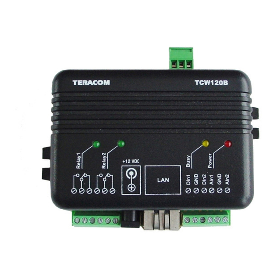
1. Short description
TCW120B is a multifunctional device for remote monitoring and management. It is an
Ethernet based controller, which is designed to work in IP-based networks and managed by
WEB interface or SNMP programs. Its I/O interface - relay outputs, analog and digital inputs,
is suitable for solving specific problems in various fields such as remote control, alarm
systems, industrial process automation, control and management of computer networks etc.
High precision digital temperature sensor is option.
2. Features
• 10 Mbit Ethernet connectivity
• Password protected web based configuration and control
• 2 digital inputs, 2 analog inputs, 1 temperature sensor input
• Two 3A/24V relay outputs
• SNMP v.1, SMTP, ICMP, VLAN support
• Sending SNMP Traps messages under certain conditions
• Sending E-mail messages under certain conditions
• Relay restart on ping/echo timeout
• TCW120B can be used as standalone device or as a part of monitoring and
management system
• MAC Address filtering
• Remote FTP firmware update
For pricing information contact Omni Instruments by phone on +44 845 9000 601 or via email at info@omni.uk.com
TCW120B
UK / Europe Office
Tel: +44 (0)845 9000 601
Fax: +44 (0)845 9000 602
info@omniinstruments.co.uk
www.omniinstruments.co.uk
Australia / Asia Pacific Office
Tel +61 (0)282 442 363
Fax +61 (0)294 751 278
info@omniinstruments.com.au
www.omniinstruments.com.au
USA / Canada Office
Tel +1-866-849-3441
Fax +1-866-628-8055
info@omniinstruments.net
www.omniinstruments.net
Advertisement
Table of Contents

Summary of Contents for Omni Instruments TCW120B
- Page 1 • MAC Address filtering • Remote FTP firmware update For pricing information contact Omni Instruments by phone on +44 845 9000 601 or via email at info@omni.uk.com UK / Europe Office Australia / Asia Pacific Office USA / Canada Office...
-
Page 2: Technical Parameters
3. Technical parameters Supply Voltage, VDC Weight, g 72 x 50 x 18 Dimensions, mm Operating temperature, °C 0 ÷ 40 Storage temperature , °C -40 ÷ 85 Analog input range, VDC Ain1 0 ÷ 20 Ain2 0 ÷ 100 Minimum high level input voltage, V Maximum low level input voltage, V Maximum input voltage for digital inputs, V... -
Page 3: Led Indicators
6. Example Applications 6.1 Remote control The controlled device is connected in series with the relay contacts. Users can operate TCW120B using a web browser or by using custom SNMP applications. Both relay outputs are managed independently of each other. - Page 4 A relay output from the monitored device is connected to one of the digital inputs of TCW120B. When an event occurs – the controller sends an E-mail message to a predefined e-mail address. SNMP Trap message is sent if custom SNMP monitoring software is used.
-
Page 5: Installation
3. Connect the I/O pins of the controller according to the required application. 4. Connect the power supply. If the red LED is blinking, it indicates that the power supply is OK. By default TCW120B comes with the following network settings: IP:192.168.1.2 , Subnet Mask: 255.255.255.0 , Default Gateway: 192.168.1.1... - Page 6 The controller supports only one active session – only one user (administrator) can operate the device. If another user tries to login, the following message appears: “Someone’s logged in” The active session will be terminated automatically, if the current user stays inactive for 2 minutes.
- Page 7 5 seconds as the maximum number of consecutive restarts is limited to 5. One of the possibilities of TCW120B is to send e-mail messages when the status of digital inputs Digital Input 1 and Digital Input 2 is changed. To do this, the following parameters must be set: •...
- Page 8 • Host Name • MAC – device MAC address If multiply TCW120B controllers are used on the same network, please change the IP address after connecting the device to the network. This will avoid devices installed on the network with the same factory default IP address at the same time.
- Page 9 • Mailserver IP – IP address of SMTP mail server • E-mail – sender e-mail 8.6 SNMP Setup page TCW120B supports SNMP v.1 that enables trap delivery to an SNMP management application. This enables the device to be part of large monitoring and control networks. The possible settings are: •...
- Page 10 SNMP trap messages are sent for the following conditions: when event occurs on Digital Input 1 or Digital Input 2 (the signal changes its state) measured voltage on Analog Input 1 и Analog Input 2 is outside the predefined range measured temperature Is outside the predefined range restart Setting range for sending SNMP trap messages is done only through SNMP.
-
Page 11: Snmp Setup
9. SNMP setup TCW120B can be configured and monitored through SNMP (Simple Network Management Protocol). This could be done using every SNMP v.1 compatible program. Parameters that can be changed, are grouped according to their functions in the tables below. - Page 12 9.3 monitor Name Access Description Syntax x.3.1.1.0 relay_1 read-write relay 1 status INTEGER { ON(1), OFF(0) } read-write relay 2 status x.3.1.2.0 relay_2 INTEGER { ON(1), OFF(0) } x.3.1.3.0 pulse_1 read-write relay 1 pulse status INTEGER { ON(1), OFF(0) } x.3.1.4.0 pulse_2 read-write relay 2 pulse status...
- Page 13 9.5 inputs Name Access Description Syntax x.5.1.1.0 input1description read-write Digital Input 1 description String (SIZE (0..10)) x.5.1.2.0 input1ActionEdge read-write Send e-mail condition RISING-FALLING x.5.1.3.0 input1action read-write Send e-mail enable/disable INTEGER { SEND(1), DONTSEND(0) } x.5.1.4.0 input1emailAddress read-write Recipient e-mail String (SIZE (0..38)) x.5.1.5.0 input1subject read-write Subject...
-
Page 14: Save Changes
INTEGER { RESTART(1), CANCEL(0) } 10. Restoring Factory Default Settings If the IP address or password are forgotten, TCW120B can be restored to its original factory default settings. To do this, please follow the steps below: - remove the power supply from the unit and open the plastic box - press and hold the RESET button then turn on the power supply - wait about 5 seconds and release the RESET button. -
Page 15: Firmware Update
TURNING OFF THE POWER SUPPLY WILL DAMAGE THE DEVICE! ftp: 329798 bytes sent in 92.44Seconds 3.57Kbytes/sec ftp> For further information contact Omni Instruments by phone on +44 845 9000 601 or via email at info@omni.uk.com Rev. 2 – April, 2011...
Need help?
Do you have a question about the TCW120B and is the answer not in the manual?
Questions and answers