Table of Contents
Advertisement
Quick Links
Advertisement
Table of Contents

Related Manuals for Jatontec JT4300M


Summary of Contents for Jatontec JT4300M
- Page 1 JATONTEC JT4300M LTE-A CPE Administrator user Manual v1.0...
-
Page 2: Table Of Contents
Table of Contents OVERVIEW ........................... 5 ....................5 PERATOR EVICE PECIFICATION ....................5 ADIO NTERFACE PECIFICATION ........................... 5 NTERFACE GETTING STARTED ........................6 CPE U ......................6 ACKING LIST AND ......................6 NSTALLING AND POWER ON LED D ..........................8 ISPLAY MANAGING CPE DEVICE ...................... - Page 3 NTP S ..........................47 ETTING ..........................48 PDATE ..........................49 AINTENANCE ............................50 PERF ............................51 FAQ AND TROUBLESHOOTING ....................52 Page 3...
- Page 4 PLEASE READ THESE SAFETY PRECAUTIONS! RF Energy Health Hazard The radio equipment described in this guide uses radio frequency transmitters. Although the power level is low, the concentrated energy from a directional antenna may pose a health hazard. Do not allow human body to keep close contact with the device for long period of time while the transmitter is operating.
-
Page 5: Overview
1. Overview The JT4300M CPE is a highly advanced LTE outdoor multi-service product solution specifically designed to meet integrated data, voice and Wi-Fi access needs for residential, business and enterprise users. The product consists of an outdoor data CPE unit (ODU) and an indoor multiservice gateway unit (HGW) that supports advanced networking, VoIP gateway and WLAN AP functionalities. -
Page 6: Getting Started
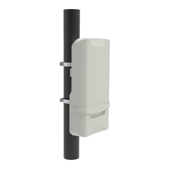
2. Getting Started Packing list and CPE Unit Upon receiving the product, please unpack the product package carefully. Each product is shipped with the following items: Table 2-1 Packing List Outdoor CPE Products Quantity ODU unit IDU unit Mounting brackets 48V DC Power adapter Ethernet Cable If you find any of the items is missing, please contact our local distributor immediately. - Page 7 Insert SIM Card Installing Outdoor Unit (ODU) – Clamp Page 7...
-
Page 8: Led Display
5th Green LED: -85 <= RSRP 3. Managing CPE Device The JT4300M offers rich management features which facilitate the task of service provider. It supports local management access, Telnet, WEB, and centralized remote OTA configuration, upgrades management and device monitoring via standard TR-069 ACS systems. The following describes the basic procedures for configuring the device for LTE operation. - Page 9 may launch a Web browser and specify http://172.16.1.1 in the address bar. A window will pop up requesting password. Input the user login password and then click the “Log in” button. After successful log on, the default home page of the WEB GUI interface will appear. Note the default password is “admin123”.
-
Page 10: System Information
4. System Information System Status The menu shows the general system info of the CPE device. It includes system, general, WAN, LAN, Wi-Fi information. Page 10... -
Page 11: Network
Network The menu shows the general network status that includes PDN interface info. Page 11... -
Page 12: Statistics Info
Statistics Info The menu shows the CPE device traffic statistics and memory usage information. Page 12... -
Page 13: Lte Configuration
5. LTE Configuration Interface Info The LTE interface info GUI gives detailed LTE information about the radio connection, the UL/DL Bandwidth, UL/DL Frequency, the receiving signal strength of the device by the LTE Info WEB GUI. Page 13... -
Page 14: Radio Settings
Radio Settings The LTE radio can be enabled or disabled via 4G Radio setting. The radio can also be reset via Reconnect. Frequency scanning step and channel settings can all be configured as follow. By default, 500KHz frequency scanning step is assumed. Page 14... -
Page 15: Pdn
This menu is used to configure the operator APN profile. You can configure single or multiple APNs for the operator network. The below shows an example of two APN configuration. The user can view the APN status info in the System Information - Network menu. Page 15... -
Page 16: Sim Card
SIM Card The SIM card menu is used to view the SIM card status and perform card restriction for SIM card. Page 16... -
Page 17: Plmn Selection
PLMN Selection The user can add and configure the PLMN list to restrict the CPE to attach. The CPE will attach to network according to the PLMN priority assigned. Page 17... -
Page 18: Cell Selection
Cell Selection The cell selection menu is used to configure how CPE will select the best cell. User can configure the “Auto Select” mode to select cell based 3GPP standard. When configured with “Auto Select & Lock”, user add the desired cell ID to the list and the CPE will attach to the appropriate cell after a full scan. -
Page 19: Pin Management
PIN Management The PIN Management menu is used to view the SIM card status and perform PIN code management for SIM card. You disable or enable the SIM card PIN check on the CPE to bind the SIM card inserted. Page 19... -
Page 20: Command
Command The Command menu is used to run LTE command via the WEB GUI interface. The user can type the command and click the “Run Command” button to execute. Page 20... -
Page 21: Network Configuration
6. Network Configuration Operation Mode Setting The default device Operation Mode is Router, and the PC connected to device LAN port will obtain IP address via DHCP client. The device operation mode could be changed from Router to Bridge if necessary as show by the following diagram: In Bridge mode, the PC which connected the LAN port of the CPE will obtain the IP directly from the network. -
Page 22: Vpn Setting Under Router Mode
VPN Setting Under Router Mode This section allows user to configure VPN service for selected connection mode. In router mode, PPTP, L2TP and GRE can be selected. In L2 Bridge mode, only L2 GRE can be configured. The router mode VPN configuration is shown below. Page 22... - Page 23 Page 23...
- Page 24 The L2TP configuration under router mode is shown below. The PPTP configuration under router mode is shown as follows. Page 24...
-
Page 25: Vpn Setting Under L2 Bridge Mode
The L2 GRE configuration under router mode is shown below. VPN Setting Under L2 Bridge Mode Under the L2 Bridge connection mode, L2 GRE or L2TP can be configured as follows. Page 25... - Page 26 Page 26...
-
Page 27: Packets Classifier
Packets Classifier This configuration menu allows user to tag DSCP or TOS value for CPE local data (Management) and LAN port data (Data). Page 27... -
Page 28: Ipv6 Setting
IPv6 Setting In this page, user configure the IPv6 operation setting for the CPE device. Page 28... -
Page 29: Ddns Setting Under Router Mode
DDNS Setting Under Router Mode This configuration menu allows user to configure use of different DDNS service for router mode operation. Client List This shows all the LAN clients that are connected to the CPE device. Page 29... -
Page 30: Wi-Fi Configuration
7. Wi-Fi Configuration Network Settings In the Wi-Fi configuration, the operator can modify the default SSID and select the desired Security Policy to protect device Wi-Fi access. For easy configuration, the operator can use one of the following three recommended common security policies for setup. ... -
Page 31: Wi-Fi Status
Wi-Fi Status The menu shows the Wi-Fi info of the CPE device. Page 31... -
Page 32: Service Configuration
8. Service Configuration Port Forwarding This menu allows user to configure the port forwarding rules for the CPE in router mode. Packet Filtering This allows user to create packet filter to control the client access. UPnP This menu allows user to configure the UPnP application for on-demand “DMZ” support. The current forwarding rules created can be viewed and cleared if required. -
Page 33: Dmz Setting
DMZ Setting This menu allows user to configure the DMZ setting for CPE in router mode. Web server, Telnet/SSH and Ping Service port can be exempted from DMZ mapping if required. By enabling DMZ option will make the specified local LAN host (DMZ IP) exposed to Internet. ... - Page 34 Page 34...
-
Page 35: Voip Configuration
9. VoIP Configuration In this configuration page, the operator requires to enter the SIP operator name, account and password information if he desires to configure the VoIP networking. The register status check box must be enabled to allow device SIP registration. The SIP register and proxy server configuration should be performed by the network operator via administration management interface. - Page 36 Page 36...
-
Page 37: Number Analysis
Number Analysis The device is collects dial numbers from external phone or fax. Dialed digits are analyzed before being sent out to another element in a VoIP network. Dial numbers can be modified according to specific needs. Rules can be setup to modified a dial number, if it meets certain condition. Page 37... -
Page 38: Call
Call Call Configuration section defined a few behaviors when a call is outgoing or incoming. Page 38... -
Page 39: Dsp
Voice is sampled and coded into digital bit stream, before they are packetized into IP packets. The following sections discuss various codecs supported by the device. Page 39... -
Page 40: Enhanced Services
Enhanced Services The device supports a rich set of supplementary services. Click on “Enhanced Services Configuration”, the following Supplementary Service Subscription are displayed in the right frame of browser window: Many of the enhanced services need to be provisioned with the proper activation codes to work with the soft switch. -
Page 41: Line Features
Line Features Line Settings specify user specific parameters for supplementary services. These settings will remain even their associated features are deactivated, so that users are not required to set them next time. Page 41... -
Page 42: Port
Port Port configuration defines physical and electrical layer parameters, such as port transmit power. Module Management The device need not be reset if changes are made are at application level, e.g. Proxy IP address change. However, the media protocol can be restarted to effect changes. Page 42... - Page 43 Page 43...
-
Page 44: System Maintenance
10. System Maintenance General Setting The menu allows user to configure the device management control and language setting. Page 44... -
Page 45: General Setting
General Setting The menu allows user to configure the WEB GUI login password. Page 45... -
Page 46: Tr069
TR069 The menu allows user to configure the necessary setting for TR069 management of the CPE device. Page 46... -
Page 47: Ntp Setting
NTP Setting The menu allows user to configure the NTP setting for the CPE device. Page 47... -
Page 48: Auto Update
Auto Update The user can select the Auto Update device’s firmware. This menu can configure the remote upgrade using FTP or HTTP. Page 48... -
Page 49: Maintenance
Maintenance This menu allows user to perform firmware upgrade via WEG GUI with option to reset to factory setting. It can also configure the remote upgrade using FTP, TFTP or HTTP. Page 49... -
Page 50: Iperf
Iperf This menu allows user to configure iPerf testing using WEB GUI interface. Both TCP and UDP tests can be supported. Remote iPerf server is required to conduct the tests. Page 50... -
Page 51: Ping
Ping This menu allows user to perform PING tests using WEB GUI interface. Both IPv4 and IPv6 can be supported. Page 51... -
Page 52: Faq And Troubleshooting
11. FAQ and Troubleshooting My PC cannot connect to the CPE. Re-plug the PC Ethernet cable and check if the PC LAN connection is up or showing activity. Check if the SYS LED is on. If it is not, check the power cord and make sure it is connected properly.
Need help?
Do you have a question about the JT4300M and is the answer not in the manual?
Questions and answers