
Summary of Contents for Parsun HF4830S60-145
- Page 1 All-in-one solar charger inverter User Manual Product models: HF4830S60-145 | HF4840S80-145 | HF4850S80-145 All-in-one solar charge inverter V11...
- Page 2 Important safety instructions Please keep this manual for future use. This manual contains all safety, installation and operating instructions for the HF Series all-in-one solar charge inverter. Please read all instructions and precautions in the manual carefully before installation and use. ...
-
Page 3: Table Of Contents
CONTENTS 1. GENERAL INFORMATION ..................... 4 1.1 P RODUCT OVERVIEW AND FEATURES ..................4 1.2 B ASIC SYSTEM INTRODUCTION ....................5 1.3 A PPEARANCE ........................... 6 1.4 D IMENSION DRAWING ......................8 2. INSTALLATION INSTRUCTIONS ................... 10 2.1 I NSTALLATION PRECAUTIONS .................... -
Page 4: General Information
1. General information 1.1 Product overview and features HF series is a new all-in-one hybrid solar charge inverter, which integrates solar energy storage & means charging energy storage and AC sine wave output. Thanks to DSP control and advanced control algorithm, it has high response speed, high reliability and high industrial standard. -
Page 5: Basic System Introduction
1.2 Basic system introduction The figure below shows the system application scenario of this product. A complete system consists of the following parts: 1. PV module: Convert light energy into DC power, and charge the battery through the all-in-one solar charge inverter, or directly invert into AC power to drive the load. 2. -
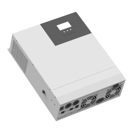
Page 6: Appearance
1.3 Appearance HF4830S60-145: ⑨ ① AC input port Cooling fan ⑩ ② AC output port Battery port ⑪ ③ CAN communication port ON/OFF rocker switch ④ ⑫ USB communication port PV port ⑤ ⑬ RS485 communication port Touch button ⑥... - Page 7 Other models: ⑨ ① Overload protector Dry contact port ⑩ ② ON/OFF rocker switch Cooling fan ⑪ ③ AC input port Battery port ⑫ ④ AC output port Cooling fan ⑬ ⑤ Grounding screw hold PV port ⑭ ⑥ RS485-2 communication port Touch the key lightly ⑮...
-
Page 8: Dimension Drawing
1.4 Dimension drawing HF4830S60-145: All-in-one solar charge inverter V11... - Page 9 Other models: All-in-one solar charge inverter V11...
-
Page 10: Installation Instructions
2. Installation instructions 2.1 Installation precautions Please read this manual carefully prior to installation to familiarize yourself with the installation steps. Be very careful when installing the battery. Wear safety goggles when installing a lead-acid liquid battery. Once coming into contact with the battery acid, rinse with clean water timely. Do not place metal objects near the battery to prevent short-circuit of the battery. -
Page 11: Wiring Specifications And Circuit Breaker Selection
Recommended PV Maximum PV Recommended air switch or Models wiring diameter input current circuit breaker type 10mm /7AWG HF4830S60-145 2P—63A HF4840S80-145 2P—63A 10mm /7AWG HF4850S80-145 10mm /7AWG 2P—63A Note: The voltage in series shall not exceed the maximum PV input open circuit voltage. - Page 12 Recommended battery input wire diameter and switch selection Rated Recommended Maximum Recommended air Models battery wiring battery charge switch or circuit diameter discharge current breaker type current HF4830S60-145 120A 2P—160A 30mm /2AWG HF4840S80-145 110A 140A 2P—160A 30mm /2AWG HF4850S80-145 125A 140A 2P—160A 30mm...
-
Page 13: Installation And Wiring
2.3 Installation and wiring Installation steps:: Step 1: Determine the installation position and the space for heat dissipation. Determine the installation position of the all-in-one solar charge inverter, such as wall surface; when installing the all-in-one solar charge inverter, ensure that there is enough air flowing through the heat sink, and space of at least 200m to the left and right air outlets of the inverter shall be left to ensure natural convection heat dissipation. - Page 14 Step 2: Remove the terminal cover Step3: Wiring HF4830S60-145: Other models: All-in-one solar charge inverter V11...
- Page 15 :Ground L:Live N:Neutral HF4830S60-145 Other models ③ Properly connect the AC output wire according to the wire sequence and terminal position shown in the figure below. Please connect the ground wire first, and then the live wire and the neutral wire. The ground wire is connected to the grounding screw hole on the cabinet through the O-type terminal.
- Page 16 Note: The grounding wire shall be as thick as possible (cross-sectional area is not less than 4mm The grounding point shall be as close as possible to the all-in-one solar charge inverter. The shorter the grounding wire, the better. PV input wiring method: ①...
- Page 17 ② Properly connect the BAT wire according to the wire sequence and terminal position shown in the figure below. BAT+: Battery positive electrode BAT-: Battery negative electrode Warnings: ① Mains input, AC output and PV array will generate high voltage. So, before wiring, be sure to disconnect the circuit breaker or fuse;...
- Page 18 Step 5: Install the terminals cover. HF4830S60-145 Other models Step 6: Turn on the all-in-one solar charge inverter First, close the circuit breaker at the battery terminal, and then turn the rocker switch on the left side of the machine to the "ON" state. The "AC/INV" indicator flashing indicates that the inverter is working normally.
-
Page 19: Operating Modes
3. Operating modes 3.1 Charging mode 1) PV priority: PV module will charge the battery preferentially, and the battery is charged by the Mains only when the PV system fails. During the day, solar energy is fully used to charge, while at night, it converts to the Mains. -
Page 20: Output Mode
3.2 Output mode PV priority mode: Switch to mains supply when the PV charging fails. This mode maximizes the use of solar energy while maintaining battery power, suitable for use in the areas with relatively stable grid. Mains priority mode: ... -
Page 21: Lcd Screen Operating Instructions
4. LCD screen operating instructions 4.1 Operation and display panel The operation and display panel is as shown below, including 1 LCD screen, 3 indicators and 4 operation buttons. Operation buttons introduction Function Description buttons Enter/Exit Settings menu Previous choice DOWN Next choice Confirm/Enter Options under the settings menu,... - Page 22 LCD screen introduction Icons Functions Icons Functions Indicates that the AC input Indicates that the inverter circuit terminal has been connected to is working the grid Indicates that the AC input mode Indicates that the machine is in in APL mode (wide voltage range) the Mains Bypass mode Indicates that the PV input terminal Indicates that the AC output is in...
- Page 23 Indicates that the current battery Indicates that the machine has an type of the machine is a lead-acid alarm battery Indicates that the battery is in Indicates that the machine is in a charging state fault condition Indicates that the AC/PV charging Indicates that the machine is in circuit is working setup mode...
- Page 24 Real-time data viewing method On the LCD main screen, press the “UP” and “DOWN” buttons to scroll through the real-time data of the machine. Parameters Parameters on the left side of the in the Parameters on the right Page screen middle of side of the screen the screen...
-
Page 25: Setup Parameters Description
4.2 Setup parameters description Buttons operation instructions: Press the “SET” button to enter the setup menu and exit the setup menu. After entering the setup menu, the parameter number [00] will flash. At this point, press the “UP” and “DOWN” buttons to select the code of parameter item to be set. Then, press the “ENT” button to enter the parameter editing mode, and the value of the parameter is flashing. - Page 26 [06] OSO activated. 230Vac Max charger current (AC charger+PV charger). Setting range: 0~140A; Max charger [07] 80A default HF4830S60-145 current Max charger current (AC charger+PV charger). Setting range: 0~120A; [08] USE User-defined; all battery parameters can be set. Sealed lead-acid battery; constant-voltage charge [08] SLd voltage: 57.6V, floating charge voltage: 55.2V.
- Page 27 Parameter Parameter Settings Description name Boost charge maximum time setting, which means the maximum charging time to reach the set voltage of Battery boost parameter [09] during constant-voltage charging. The [10] 120 default charge time setting range is 5min~900min, with a step of 5 minutes.
- Page 28 Parameter Parameter Settings Description name Equalizing charge time; setting range: 5min~900min, Battery [18] 120 default with a step of 5 minutes; valid for vented lead-acid equalized time battery and sealed lead-acid battery Battery Equalizing charge delay; setting range: 5min~900min, equalized time [19] 120 default with a step of 5 minutes;...
- Page 29 Max PV charger current. Setting range: [36] 60A default Max PV charger 0~60A (HF4830S60-145) current [36] 80A default Max PV charger current. Setting range: 0~80A Battery fully After the battery is fully charged, it needs to be lower...
-
Page 30: Battery Type Parameters
4.3 Battery type parameters For Lead-acid Battery : Battery type Sealed lead Colloidal lead Vented lead User-defined acid battery acid battery acid battery (User) (SLD) (GEL) (FLD) Parameters Overvoltage disconnection 40~60V voltage (Adjustable) Battery fully charged recovery point(setup item (Adjustable) (Adjustable) (Adjustable) (Adjustable) - Page 31 For Lithium Battery : Ternary Ternary Lithium iron Lithium iron Battery type Lithium iron lithium lithium phosphate phosphate phosphate battery battery battery battery battery (LF14) Parameters (N13) (N14) (LF16) (LF15) Overvoltage disconnection voltage Battery fully charged 50.4V 54.8V 53.6V 50.4V 47.6V recovery point(setup (Adjustable)
-
Page 32: Other Functions
5. Other functions 5.1 Dry node Working principle: This dry node can control the ON/OFF of the diesel generator to charge the battery. ① Normally, the terminals are that the NC-N point is closed and the NO-N point is open; ② When the battery voltage reaches the low voltage disconnection point, the relay coil is energized, and the terminals turn to that the NO-N point is closed while NC-N point is open. -
Page 33: Protection
6. Protection 6.1 Protections provided Protections Description PV current/power When charging current or power of the PV array configured exceeds limiting protection the PV rated, it will charge at the rated. At night, the battery is prevented from discharging through the PV PV night reverse- module because the battery voltage is greater than the voltage of PV current protection... - Page 34 Output again 3 minutes after an overload protection, and turn the Overload output off after 5 consecutive times of overload protection until the protection machine is re-powered. For the specific overload level and duration, refer to the technical parameters table in the manual. PV reverse polarity When the PV polarity is reversed, the machine will not be damaged.
-
Page 35: Fault Code Meaning
6.2 Fault code meaning Whether it Fault code Fault name affects the Description output or not BatVoltLow Battery undervoltage alarm 【01】 Battery discharge average current BatOverCurrSw 【02】 overcurrent software protection BatOpen Battery not-connected alarm 【03】 BatLowEod Battery undervoltage stop discharge alarm 【04】... -
Page 36: Handling Measures For Part Of Faults
6.3 Handling measures for part of faults Fault Faults Handling measures code Check if the battery air switch or the PV air switch has been closed; if the switch is in the "ON" state; Display No display on the screen press any button on the screen to exit the screen sleep mode. -
Page 37: System Maintenance
7. System maintenance In order to maintain the best long-term performance, it is recommended to conduct following checks twice a year. Make sure that the airflow around the unit is not blocked and remove any dirt or debris from the heat sink. -
Page 38: Technical Parameters
8. Technical parameters Models HF4830S60 -145 HF4840S80 -145 HF4850S80-145 AC mode Rated input voltage 220/230Vac Input voltage range (170Vac~280Vac) ±2%/(90Vac-280Vac) ±2% Frequency 50Hz/ 60Hz (Auto detection) 47±0.3Hz ~ 55±0.3Hz (50Hz); Frequency Range 57±0.3Hz ~ 65±0.3Hz (60Hz); Overload/short circuit Circuit breaker protection Efficiency >95%... - Page 39 Maximum charge current(can 0-60A be set) Charge current error ± 5Adc Charge voltage range 40 –58Vdc Short circuit protection Circuit breaker and blown fuse Circuit breaker specifications Overcharge protection Alarm and turn off charging after 1 minute PV charging Maximum PV open circuit 145Vdc voltage PV operating voltage range...
Need help?
Do you have a question about the HF4830S60-145 and is the answer not in the manual?
Questions and answers