Table of Contents
Advertisement
Quick Links
Advertisement
Table of Contents

Subscribe to Our Youtube Channel
Related Manuals for Gigabyte R152-P31


Summary of Contents for Gigabyte R152-P31
- Page 1 R152-P31 Ampere® Altra® ARM Server - 1U 10-Bay User Manual Rev. 1.0...
- Page 2 GIGABYTE's prior written permission. Documentation Classifications In order to assist in the use of this product, GIGABYTE provides the following types of documentation: User Manual: detailed information & steps about the installation, configuration and use of this product (e.g.
- Page 3 Conventions The following conventions are used in this user's guide: NOTE! Gives bits and pieces of additional information related to the current topic. CAUTION! Gives precautionary measures to avoid possible hardware or software problems. WARNING! Alerts you to any damage that might result from doing or not doing specific actions.
- Page 4 Server Warnings and Cautions Before installing a server, be sure that you understand the following warnings and cautions. WARNING! To reduce the risk of electric shock or damage to the equipment: • Do not disable the power cord grounding plug. The grounding plug is an important safety feature.
- Page 5 Electrostatic Discharge (ESD) CAUTION! ESD CAN DAMAGE DRIVES, BOARDS, AND OTHER PARTS. WE RECOMMEND THAT YOU PERFORM ALL PROCEDURES AT AN ESD WORKSTATION. IF ONE IS NOT AVAILABLE, PROVIDE SOME ESD PROTECTION BY WEARING AN ANTI-STATIC WRIST STRAP AT- TACHED TO CHASSIS GROUND -- ANY UNPAINTED METAL SURFACE -- ON YOUR SERVER WHEN HANDLING PARTS.
- Page 6 CAUTION! Risk of explosion if battery is replaced incorrectly or with an incorrect type. Replace the battery only with the same or equivalent type recommended by the manufacturer. Dispose of used bat- teries according to the manufacturer’s instructions.
-
Page 7: Table Of Contents
Table of Contents Chapter 1 Hardware Installation ..................9 Installation Precautions ..................9 Product Specifications ..................10 System Block Diagram ................... 13 Chapter 2 System Appearance ..................15 Front View ...................... 15 Rear View ....................... 15 Front Panel LED and Buttons ................ 16 Rear System LAN LEDs ................. - Page 8 5-2-3 General Watchdog ....................48 5-2-4 APEI Configuration ....................49 5-2-5 PCI Subsystem Settings ..................50 5-2-6 Info Report Configuration ..................57 5-2-7 USB Configuration ....................58 5-2-8 Network Stack ......................59 5-2-9 NVMe Configuration ....................60 5-2-10 Power Restore Configuration .................61 5-2-11 Intel(R) I350 Gigabit Network Connection ..............62 5-2-12 MAC IPv4 Network Configuration ................64 5-2-13 MAC IPv6 Network Configuration ................65 Chipset Setup Menu ..................
-
Page 9: Chapter 1 Hardware Installation
Chapter 1 Hardware Installation Installation Precautions The motherboard/system contain numerous delicate electronic circuits and components which can become damaged as a result of electrostatic discharge (ESD). Prior to installation, carefully read the service guide and follow these procedures: • Prior to installation, do not remove or break motherboard S/N (Serial Number) sticker or warranty sticker provided by your dealer. -
Page 10: Product Specifications
Product Specifications NOTE: We reserve the right to make any changes to the product specifications and product-related information without prior notice. Ampere® Altra® Processor Š Single processor, 7nm technology Š Up to 80-core per processor Š Socket Single socket Š LGA4926 Š... - Page 11 Internal I/O 2 x M.2 slots Š 1 x USB 3.0 header Š 1 x USB 2.0 header Š 1 x TPM header Š Socket Security 1 x Front panel header Š 1 x HDD back plane board header Š 1 x PMBus connector Š...
- Page 12 Š 190-310V, 5-3A Š DC Output: 650W +12V/52.9A +5Vsb/4.0A System Aspeed® AST2500 management controller Š Management GIGABYTE Management Console (AMI MegaRAC SP-X) web interface Š Dashboard Š JAVA Based Serial Over LAN Š Security ocket HTML5 KVM Š Sensor Monitor (Voltage, RPM, Temperature, CPU Status …etc.) Š...
-
Page 13: System Block Diagram
System Block Diagram 8-Channel DDR4, 16 x DIMMs Speed up to 3200 MHz Riser CRS101D PCIe4.0 x16 PCIe x16 slot 4-bay 2.5" NVMe PCIe3.0 x4 per port PCIe4.0 x4 PCIe4.0 x16 PCIe4.0 x4 CSTO180 SATA card 2 x SlimSAS PCIe3.0 x16 OCP 2.0 mezzanine BIOS PCIe2.0 x2... - Page 14 This page intentionally left blank Hardware Installation - 14 -...
-
Page 15: Chapter 2 System Appearance
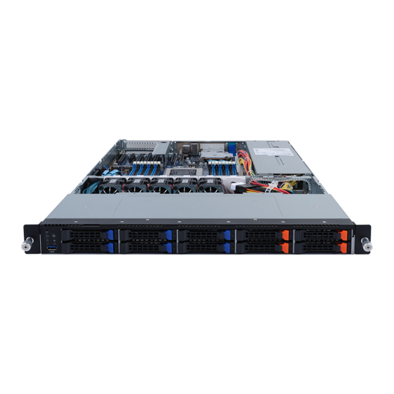
Chapter 2 System Appearance Front View HDD#0 HDD#2 HDD#4 HDD#6 HDD#8 HDD#1 HDD#3 HDD#5 HDD#7 HDD#9 Description Front USB 3.0 Port Front Panel LEDs and Buttons NOTE! The Orange HDD Latch Supports NVMe • Please Go to Chapter 2-3 Front Panel LED and Buttons for detail description of function LEDs. -
Page 16: Front Panel Led And Buttons
Front Panel LED and Buttons Name Color Status Description Reset Button Press the button to reset the system. ID Button Press the button to activate system identification Green System is powered on Green Blink System is in ACPI S1 state (sleep mode) Power button •... -
Page 17: Rear System Lan Leds
Rear System LAN LEDs Name Color Status Description Yellow 1 Gbps data rate 1GbE Green 100 Mbps data rate Speed LED 10 Mbps data rate Link between system and 1GbE Green network or no access Link/ Blink Data transmission or receiving is occurring Activity No data transmission or receiving is occurring... -
Page 18: Power Supply Unit (Psu) Led
Power Supply Unit (PSU) LED PSU LED State Description Indicates no AC power to all power supplies 1Hz Blink GREEN Indicates AC present/ only standby on/ Cold redundant mode Indicates power supply critical event causing shut down: failure, OCP, OVP, Fan Fail, UVP Indicates AC cord unplugged or AC power lost;... -
Page 19: Hard Disk Drive Leds
Hard Disk Drive LEDs HDD Present RAID SKU Rebuilding LED1 Locate HDD Fault Access (No Access) Disk LED Green ON(*1) BLINK (*2) (LED on Back Panel) Amber No RAID configuration Green ON(*1) (via HBA) Removed HDD Slot (LED on Back Panel) Amber Green BLINK (*2) - Page 20 This page intentionally left blank System Appearance - 20 -...
-
Page 21: Chapter 3 System Hardware Installation
Chapter 3 System Hardware Installation Pre-installation Instructions Computer components and electronic circuit boards can be damaged electrostatic discharge. Working on computers that are still connected to a power supply can be extremely dangerous. Follow the simple guidelines below to avoid damage to your computer or injury to yourself. -
Page 22: Removing Chassis Cover
Removing Chassis Cover Before you remove or install the system cover • Make sure the system is not turned on or connected to AC power. Follow these instructions to remove the rear system cover: Loosen and remove the thumbscrew securing the back cover. Push down the indentation located at the side of the back chassis Slide the cover horizontally to the back and remove the cover in the direction of the arrow. -
Page 23: Removing And Installing The Fan Duct
Removing and Installing the Fan Duct Follow these instructions to remove/install the fan duct: Lift up to remove the two fan ducts To install the fan duct, align the fan duct with the guiding groove. Push down the fan duct into chassis until its firmly seats - 23 - System Hardware Installation... -
Page 24: Removing And Installing The Cpu
Removing and Installing the CPU Read the following guidelines before you begin to install the CPU: • Make sure that the motherboard supports the CPU. • Always turn off the computer and unplug the power cord from the power outlet before installing the CPU to prevent hardware damage. -
Page 25: Installing The Memory
Installing the Memory Read the following guidelines before you begin to install the memory: • Make sure that the motherboard supports the memory. It is recommended that memory of the same capacity, brand, speed, and chips be used. • Always turn off the computer and unplug the power cord from the power outlet before installing the memory to prevent hardware damage. -
Page 26: Installing A Memory
3-4-2 Installing a Memory Before installing a memory module, make sure to turn off the computer and unplug the power cord from the power outlet to prevent damage to the memory module. Be sure to install DDR4 DIMMs on this motherboard. Follow these instructions to install the Memory: Insert the DIMM memory module vertically into the DIMM slot, and push it down. -
Page 27: Altra Platform Ddr4 Suggest Configuration Table
3-4-4 Altra Platform DDR4 Suggest Configuration Table Channels used ( = Memory Installed) Channels Used DIMM_P0_E0 DIMM_P0_F0 DIMM_P0_G0 DIMM_P0_H0 DIMM_P0_D0 DIMM_P0_C0 DIMM_P0_B0 DIMM_P0_A0 Channels used ( = Memory Installed) Channels Used DIMM_P0_E0 DIMM_P0_F0 DIMM_P0_G0 DIMM_P0_H0 DIMM_P0_D0 DIMM_P0_C0 DIMM_P0_B0 DIMM_P0_A0 DIMM_P0_E1 DIMM_P0_F1 DIMM_P0_G1 DIMM_P0_H1... -
Page 28: Installing The Pci Expansion Card
Installing the PCI Expansion Card • Voltages can be present within the server whenever an AC power source is connected. This voltage is present even when the main power switch is in the off position. Ensure that the system is powered-down and all power sources have been disconnected from the server prior to installing a PCI card. -
Page 29: Installing The Hard Disk Drive
Installing the Hard Disk Drive Read the following guidelines before you begin to install the Hard disk drive: • Take note of the drive tray orientation before sliding it out. • The tray will not fit back into the bay if inserted incorrectly. •... -
Page 30: Installing The Mezzanine Card (Optional)
Installing the Mezzanine Card (Optional) Follow these instructions to install a mezzanine card: Remove the screw securing the mezzanine card slot cover. Remove the slot cover from the system. Insert the OCP 2.0 mezzanine card into the compartment ensuring that the card is firmly connected to the connector on the motherboad. -
Page 31: Installing And Removing An M.2 Solid State Drive
Installing and Removing an M.2 Solid State Drive Follow these instructions to install an optional M.2 solid state drive (SSD): NOTE: To install/remove the M.2 heatsink use a No. 1 Phillips-head screwdriver with a screw torque of 1.5 ± 0.2 kgf*cm Place the solid state drive into the M.2 connector. -
Page 32: Replacing The Fan Assembly
Replacing the FAN Assembly • Voltages can be present within the server whenever an AC power source is connected. This voltage is present even when the main power switch is in the off position. Ensure that the system is powered-down and all power sources have been disconnected from the server prior to removing/installing a system fan. -
Page 33: Replacing The Power Supply
3-10 Replacing the Power Supply Follow these instructions to replace the power supply: Press the retaining clip on the left side of the power supply unit along the direction of the arrow. Pull the power supply handle at the same time and pull out the power supply unit. Insert the replacement power supply unit firmly into the chassis. -
Page 34: Cable Routing
3-11 Cable Routing Front Switch Cable/Front LED Cable Front Panel USB 3.0 Cable HDD Back Plane Board Power Cable HDD Back Plane Board Signal Cable System Hardware Installation - 34 -... - Page 35 U.2 NVMe to HDD Back Plane Board Cable U.2 NVMe to HDD Back Plane Board Cable (NMVe0) (NMVe1) U.2 NVMe to HDD Back Plane Board Cable U.2 NVMe to HDD Back Plane Board Cable (NMVe2) (NMVe3) - 35 - System Hardware Installation...
- Page 36 SATA to HDD Back Plane Board Cable SATA to HDD Back Plane Board Cable (SATA0) (SATA1) SL_CN1 SL_CN1 SL_CN2 SATA0 SATA1 System Hardware Installation - 36 -...
-
Page 37: Chapter 4 Motherboard Components
Chapter 4 Motherboard Components Motherboard Components 14 15 16 27 28 Item Description SlimLine SAS Connector (U2_3) SlimLine SAS Connector (U2_2) SlimLine SAS Connector (U2_1) SlimLine SAS Connector (U2_0) Front panel USB 3.0 Connector Front Panel Connector HDD Back Plane Board Connector - 37 - Motherboard Components... - Page 38 M.2 Connector (PCIe4 x4, NGFF-22110) M.2 Connector (PCIe4 x4, NGFF-22110) USB 2.0 Connector Serial Port Cable Connector BMC Firmware Readiness LED IPMB Connector PCIe x16 Slot #1 (x8 Signal) PCIe x8 Slot #2 (x8 Signal) PCIe x16 Slot #3 (x8 Signal) PCIe x16 Slot #4 (x16 Signal) PCIe x16 Slot #5 (x8 Signal) PCIe x16 Slot #6 (x16 Signal)
-
Page 39: Jumper Settings
Jumper Settings NCSI Switch OCP Mezzanine Onboard LAN Default Clear CMOS CLR_CMOS Enable - 39 - Motherboard Components... - Page 40 This page intentionally left blank Motherboard Components - 40 -...
-
Page 41: Chapter 5 Bios Setup
Chapter 5 BIOS Setup BIOS (Basic Input and Output System) records hardware parameters of the system in the EFI on the motherboard. Its major functions include conducting the Power-On Self-Test (POST) during system startup, saving system parameters and loading operating system, etc. BIOS includes a BIOS Setup program that allows the user to modify basic system configuration settings or to activate certain system features. - Page 42 Main This setup page includes all the items in standard compatible BIOS. Advanced This setup page includes all the items of AMI BIOS special enhanced features. (ex: Auto detect fan and temperature status, automatically configure hard disk parameters.) ...
-
Page 43: The Main Menu
The Main Menu Once you enter the BIOS Setup program, the Main Menu (as shown below) appears on the screen. Use arrow keys to move among the items and press <Enter> to accept or enter other sub-menu. Main Menu Help The on-screen description of a highlighted setup option is displayed on the bottom line of the Main Menu. - Page 44 Parameter Description BIOS Information Access Level Display the privileges level information. System Project Name Displays the system project name information. Project Name Displays the motherboard project name information. Project Version Displays version number of the BIOS setup utility. Build Date and Time Displays the date and time when the BIOS setup utility was created.
-
Page 45: Advanced Menu
Advanced Menu The Advanced menu display submenu options for configuring the function of various hardware components. Select a submenu item, then press [Enter] to access the related submenu screen. - 45 - BIOS Setup... -
Page 46: Trusted Computing
5-2-1 Trusted Computing Parameter Description Configuration Select Enabled to activate TPM support feature. Security Device Support Options available: Enable/Disable. Default setting is Enable. BIOS Setup - 46 -... -
Page 47: Acpi Settings
5-2-2 ACPI Settings Parameter Description ACPI Settings Enable or disable BIOS ACPI auto configuration. Enable ACPI Auto Configuration Options available: Enabled/Disabled. Default setting is Enabled. Enable or disable CPPC. Enable CPPC Options available: Enable/Disable. Default setting is Enabled. Options available: Enabled/Disabled. Default setting is Disabled. Enable DVFS Mode Options available: Enabled/Disabled. -
Page 48: General Watchdog
5-2-3 General Watchdog Parameter Description General Watchdog Timer Timeout when SCP will reset system if it doesn't receive response from ARMv8. Secure Watchdog Timeout Options available: 5 minutes/6 minutes/10 minutes/15 minutes/25 minutes. Default setting is 5 minutes. Options available: 5 minutes/6 minutes/10 minutes/15 minutes/25 minutes. BIOS Watchdog Timeout Default setting is 5 minutes. -
Page 49: Apei Configuration
5-2-4 APEI Configuration Parameter Description APEI Configuration Enable/Disable ACPI Platform Error Interface support. APEI Enable Options available: Enabled/Disabled. Default setting is Disabled. - 49 - BIOS Setup... -
Page 50: Pci Subsystem Settings
5-2-5 PCI Subsystem Settings BIOS Setup - 50 -... - Page 51 Parameter Description AMI PCI Bus Driver Version Displays the AMI PCI Bus Driver version information. Enable/Disable memory mapped I/O to 4GB or greater address Above 4G Decoding space (Above 4G Decoding). Options available: Enabled/Disabled. Default setting is Disabled. If the system has SR-IOV capable PCIe devices, this item SR-IOV Support Enable/Disable Single Root IO Virtualization Support.
- Page 52 5-2-5-1 PCI Express GEN 1 Settings Parameter Description PCI Express GEN1 Device Register Settings Relaxed Ordering Š – Enable or disable PCI Express Device Relaxed Ordering. Options available: Enabled/Disabled. Default setting is Enabled. Extend Tag Š – If enabled, allows device to use 8-bit Tag field as a requester.
- Page 53 Parameter Description PCI Express Device Link Register Settings Maximum Read Request Š – Set Maximum Read Request of PCI Express Device or allow System BIOS to select the value. Options available: Auto/128 /256/512/1024/2048/4096 Bytes. Default setting is Auto. Extended Synch Š...
- Page 54 5-2-5-2 PCI Express GEN 2 Settings BIOS Setup - 54 -...
- Page 55 Parameter Description PCI Express GEN2 Device Register Settings Completion Timeout Š – In device Functions that support Completion Timeout programmability, allows system software to modify the Completion Timeout value. 'Default' 50us to 50ms. If 'Shorter' is selected, software will use shorter timeout ranges supported by hardware.
- Page 56 Parameter Description PCI Express GEN2 Device Register Settings IDO Request Enable Š – If supported by hardware and set to 'Enabled', this permits setting the number of ID-Based Ordering (IDO) bit (Attribute[2]) requests to be initiated. Options available: Enabled/Disabled. Default setting is Disabled. IDO Completion Enable Š...
-
Page 57: Info Report Configuration
5-2-6 Info Report Configuration Parameter Description Info Report Configuration Post Report Enable/Disable Post Report support. Post Report Options available: Enabled/Disabled. Default setting is Enabled. Options available: 0/1/2/3/4/5/6/78/9/10/Util Press ESC. Delay Time Default setting is 1. Error Message Report Enable/Disable Info Error Message support. Info Error Message Options available: Enabled/Disabled. -
Page 58: Usb Configuration
5-2-7 USB Configuration Parameter Description USB Configuration USB Module Version Displays USB module version information. USB Controller Displays the supported USB controllers. USB Devices: Displays the USB devices connected to the system. Enable/Disable the XHCI (USB 3.0) Hand-off support. XHCI Hand-off Options available: Enabled/Disabled. -
Page 59: Network Stack
5-2-8 Network Stack Parameter Description Enable/Disable the UEFI network stack. Network Stack Options available: Enabled/Disabled. Default setting is Enabled. Enable/Disable the Ipv4 PXE feature. Ipv4 PXE Support Options available: Enabled/Disabled. Default setting is Enabled. Enable/Disable the Ipv4 HTTP feature. Ipv4 HTTP Support Options available: Enabled/Disabled. -
Page 60: Nvme Configuration
5-2-9 NVMe Configuration Parameter Description NVMe controller and Drive Displays the NVMe devices connected to the system. Information BIOS Setup - 60 -... -
Page 61: Power Restore Configuration
5-2-10 Power Restore Configuration Parameter Description Specify what state when power is re-applied after a power failure (G3 state). Power Restore Options available: Last State/Power On/Power Off. Default setting is Last State. - 61 - BIOS Setup... -
Page 62: Intel(R) I350 Gigabit Network Connection
5-2-11 Intel(R) I350 Gigabit Network Connection BIOS Setup - 62 -... - Page 63 Parameter Description Press [Enter] to configure advanced items. Link Speed Š – Allows for automatic link speed adjustment. – Options available: Auto Negotiated/10 Mbps Half/10 Mbps Full/100 Mbps Half/100 Mbps Full. Default setting is Auto Negotiated. NIC Configuration Wake On LAN Š...
-
Page 64: Mac Ipv4 Network Configuration
5-2-12 MAC IPv4 Network Configuration Parameter Description Options available: Enabled/Disabled. Default setting is Disabled. Configured (Note) Options available: Enabled/Disabled. Default setting is Enabled. Enable DHCP Local IP Address Press [Enter] to configure local IP address. Local NetMask Press [Enter] to configure local NetMask. Local Gateway Press [Enter] to configure local Gateway Local DNS Servers... -
Page 65: Mac Ipv6 Network Configuration
5-2-13 MAC IPv6 Network Configuration Parameter Description Enter Configuration Menu Press [Enter] for configuration of advanced items. - 65 - BIOS Setup... -
Page 66: Chipset Setup Menu
Chipset Setup Menu Chipset Setup menu displays submenu options for configuring the function of the North Bridge. Select a submenu item, then press [Enter] to access the related submenu screen. Parameter Description CPU Configuration Press [Enter] for configuration of advanced items. Memory Slot Configuration Press [Enter] for configuration of advanced items. -
Page 67: Cpu Configuration
5-3-1 CPU Configuration Parameter Description CPU Configuration Numbers of processor Displays the number of installed processor information. enabled Option: Default/2/4/6/8/10/12/14/16/18/20/22/24/26/28/30/32/34/36..80. Enable number of cores Default Setting is Default. ARM ERRATA 1542419 Option available: Disable I-Cache coherency/Software solution/Disable. workaround Default Setting is Disable I-Cache coherency. Option available: Monolithic/Hemisphere/Quadrant. -
Page 68: Memory Slot Information
5-3-2 Memory Slot Information Parameter Description Memory Configuration Total Memory Effective Memory Displays the technical specifications for the installed DIMM. Memory Speed Memory Operating Speed Option available: Auto/2133/2400/2666/2933/3200. Default setting: Auto. Selection Fine Granularity Refresh Select DDR Fine Granularity Refresh (FGR) mode. Option available: 1x/2x/4x. - Page 69 5-3-2-1 Memory RAS and Performance Configuration Parameter Description Memory RAS and Performance Configuration Option available: Disabled/SECDED/Symbol ECC Mode Default setting: SECDED. Defer uncorrectable read Option available: Enabled/Disabled. Default setting: Disabled. errors Option available: Enabled/Disabled. Fault handling interrupt Default setting: Enabled. Option available: 1..24.
- Page 70 5-3-2-2 NVDIMM-N Configuration Parameter Description NVDIMM-N Configuration Socket0 Configuration Select NVDIMM-N Mode. Mode Selection Option available: Non-NVDIMM/Non-Hashed/Hashed/Auto. Default setting: Auto. BIOS Setup - 70 -...
-
Page 71: Ras Configuration
5-3-3 RAS Configuration Parameter Description RAS Configuration Option available: Enabled/Disabled. Hardware EINJ Default setting: Disabled. Option available: Enabled/Disabled. PCIe AER Firmware First Default setting: Disabled. DDR CE Threshold Press '+" or "-" to configure the threshold. Processor CE Threshold Press '+" or "-" to configure the threshold. DDR Kink Error Threshold Press '+"... -
Page 72: Pcie Root Complex Configuration
5-3-4 PCIE Root Complex Configuration Parameter Description PCIE Root Complex Configuration Option available: Manual/Default. PCIe Lanes Bifurcation Default setting: Default. Enable/Disable PMU feature for SMMU. SMMU Pmu Option available: Enabled/Disabled. Default setting: Disabled. Enable/Disable on-board VGA. On-board VGA Option available: Enabled/Disabled. Default setting: Enabled. -
Page 73: Server Management Menu
Server Management Menu Parameter Description Enable/Disable interfaces to communicate with BMC. BMC Support Options available: Enabled/Disabled. Default setting is Enabled. System Event Log Press [Enter] to configure advanced items. BMC self test Press [Enter] to configure advanced items. View FRU Press [Enter] to view the advanced items. -
Page 74: System Event Log
5-4-1 System Event Log Parameter Description Enabling / Disabling Options Change this item to enable or disable all features of System Event SEL Components Logging during boot. Options available: Enabled/Disabled. Default setting is Enabled. Erasing Settings Choose options for erasing SEL. Erasing SEL Options available: No/Yes, On next reset/Yes, On every reset. -
Page 75: Bmc Self Test
5-4-2 BMC self test Parameter Description log area usage =00 out of 20 logs Options available: No/Yes, On next reset/Yes, On every reset. Erase Log Default setting is No. Configuration for reactions to a full log. When Log is full Option available: Do not log any more/Clear Log. -
Page 76: View Fru Information
5-4-3 View FRU Information The FRU page is a simple display page for basic system ID information, as well as System product information. Items on this window are non-configurable. (Note) The model name will vary depends on the product you purchased. BIOS Setup - 76 -... -
Page 77: Bmc Network Configuration
5-4-4 BMC Network Configuration Parameter Description BMC network configuration Lan Channel 1 Select to configure LAN channel parameters statically or dynamically (DHCP). Do nothing option will not modify any BMC network parameters Configuration Address source during BIOS phase. Options available: Unspecified/Static/DynamicBmcDhcp. Default setting is DynamicBmcDhcp. -
Page 78: Security Menu
Security Menu The Security menu allows you to safeguard and protect the system from unauthorized use by setting up access passwords. There are two types of passwords that you can set: • Administrator Password Entering this password will allow the user to access and change all settings in the Setup Utility. •... -
Page 79: Secure Boot
5-5-1 Secure Boot Parameter Description System Mode Displays the system is in User mode or Setup mode. Secure Boot requires all the applications that are running during the booting process to be pre-signed with valid digital certificates. This way, the system knows all the files being loaded before Windows loads and gets to the login screen have not been tampered with. - Page 80 Parameter Description Press [Enter] to configure advanced items. Please note that this item is configurable when Secure Boot Mode is set to Custom. Provision Factory Defaults Š – Allows to provision factory default Secure Boot keys when system is in Setup Mode.
-
Page 81: Boot Menu
Boot Menu The Boot menu allows you to set the drive priority during system boot-up. BIOS setup will display an error message if the legacy drive(s) specified is not bootable. Parameter Description Boot Configuration Number of seconds to wait for setup activation key. 65535 (0xFFFF) Setup Prompt Timeout means indefinite waiting. - Page 82 Parameter Description Dump full Setup Data Dump non-default Setup Data Restore Setup Date New UEFI OS Boot Option Option available: Default/Place First/Place Last. Default setting is Place First/. Policy FIXED BOOT ORDER Priorities Press [Enter] to configure the boot priority. By default, the server searches for boot devices in the following sequence: Boot Option #1 / #2 / #3 / #4 /...
-
Page 83: Save & Exit Menu
Save & Exit Menu The Exit menu displays the various options to quit from the BIOS setup. Highlight any of the exit options then press Enter. Parameter Description Save Options Saves changes made and closes the BIOS setup. Save Changes and Exit Options available: Yes/No. -
Page 84: Bios Post Beep Code (Ami Standard)
BIOS POST Beep code (AMI standard) 5-8-1 PEI Beep Codes # of Beeps Description Memory not Installed. Memory was installed twice (InstallPeiMemory routine in PEI Core called twice) Recovery started DXEIPL was not found DXE Core Firmware Volume was not found Recovery failed S3 Resume failed Reset PPI is not available...
Need help?
Do you have a question about the R152-P31 and is the answer not in the manual?
Questions and answers