
Related Manuals for Sonics VCX2500

Summary of Contents for Sonics VCX2500
- Page 1 ULTRASONIC PROCESSOR Part No. VCX2500 OPERATION MANUAL Rev. 12-21 Sonics & Materials, Inc. 53 Church Hill Rd. Newtown, CT 06470 USA Phone: 203.426.0101 info@sonics.com www.sonics.com...
-
Page 2: Table Of Contents
5.3. INSTALLING THE ULTRASONIC PROCESSOR........... 10 5.4. CONVERTER COOLING ................11 6. DESCRIPTIONS OF COMPONENTS / FUNCTIONS OF CONTROLS ....12 6.1. VCX2500 FRONT PANEL ................12 6.2. VCX2500 REAR PANEL ................13 6.3. FUNCTIONS OF KEYS CONTROLS & CONNECTORS ....... 14 6.4. -
Page 3: Warranty
1. WARRANTY Your Ultrasonic Processor is warranted and backed by the manufacturer for a period of 3 years from the date of shipment against defects in material and workmanship under normal use as described in this instruction manual. During the warranty period, the manufacturer will, at its option, as the exclusive remedy, either repair or replace without charge for material and labor, the part(s) which prove to be defective, provided the unit is returned to us properly packed with all transportation charges prepaid. -
Page 4: Warnings
2. WARNINGS Please read the manual in its entirety. Necessary instruction and guidance are provided to help ensure the successful operation of this device. Observe the following: High voltage is present in the power supply, converter and high frequency cable. There are no user-serviceable ... -
Page 5: Specifications
3. SPECIFICATIONS Power Supply VCX2500 Input Voltage 198 VAC – 264 VAC @ 50/60 Hz, Single Phase Rated Current 30 Amps Weight 61 lbs. (27.7 Kg) H x W x D: 9 x 17.5 x 28” Dimensions (240 x 445 x 711mm) Output Voltage 1000 VRMS (max.) - Page 6 Environmental Pollution Degree Installation Category Indoor Use Only Environment Operating Limits Temperature: 41 - 104ºF (5 - 40ºC) Relative Humidity 10 - 95% (Non Condensing) Altitude: 6,651 ft. (2000 m) Temperature: 35 -120 ºF (2 - 49 ºC) Shipping/Storage Relative Humidity 10 - 95% (Non Condensing) Ambient Pressure Extremes: 40,000 ft.
-
Page 7: Principles Of Operation
4. PRINCIPLES OF OPERATION The ultrasonic power supply transforms AC line power to a 20 KHz signal that drives a piezoelectric converter/transducer. This electrical signal is converted by the transducer to a mechanical vibration due to the characteristics of the internal piezoelectric crystals. The vibration is amplified and transmitted down the length of the horn/probe where the tip longitudinally expands and contracts. - Page 8 to ensure that the excursion at the probe tip remains constant. The displayed wattage readings will vary as the load changes; however, the amplitude will remain the same. The resistance to the movement of the probe determines how much power will be delivered to maintain amplitude.
-
Page 9: Installation
The Ultrasonic Processor requires a fused, single phase 3-terminal grounding type electrical outlet capable of supplying 230 +/- 10% VAC, 50/60 Hz, 30 amps. If the desired plug type is different for your country or region see the wiring diagram below: VCX2500 VCX2500 WARNING... -
Page 10: Installing The Ultrasonic Processor
5.3. INSTALLING THE ULTRASONIC PROCESSOR The ultrasonic processor should be installed in an area that is free from excessive dust, dirt, explosive and corrosive fumes, and extremes of temperature and humidity. If processing flammable liquids, use an approved fume hood and do not place the power supply in the fume hood. -
Page 11: Converter Cooling
5.4. CONVERTER COOLING The nature of sonication causes the probe, converter and sample temperature to increase during operation. Processing samples requires significant amounts of energy and some of this energy manifests as heat in the converter and probe. The converter contains sensitive internal crystals which can crack due to overheating, which would require the converter to be replaced. -
Page 12: Descriptions Of Components / Functions Of Controls
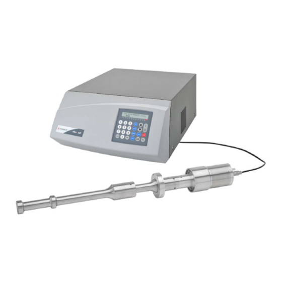
6. DESCRIPTIONS OF COMPONENTS / FUNCTIONS OF CONTROLS 6.1. VCX2500 FRONT PANEL Power Supply (VCX2500) Converter Cable (201-0106) Converter Booster (CV-294) (BHN294T25) 1.5” Probe (630-0702) Page 12 of 30... -
Page 13: Vcx2500 Rear Panel
6.2. VCX2500 REAR PANEL 9 Pin Converter Temperature Footswitch Connector Cable Socket Probe Jack Jack Circuit Board Fuse Circuit Breaker Power Cable Page 13 of 30... -
Page 14: Functions Of Keys Controls & Connectors
6.3. FUNCTIONS OF KEYS CONTROLS & CONNECTORS FRONT PANEL Displays prompts and control parameters including: • Amplitude selected • Output power delivered to the probe in watts • Selected duration of processing • Actual processing time LCD display • Elapsed time •... - Page 15 Controls the amplitude of vibration at the probe tip. AMPL Used with the AMPL key when the unit is on stand-by to set the amplitude of vibration at the probe tip. Also used to increase or ▲ ▼ decrease the amplitude in small increments while the unit is running. To accomplish this task, depress the ENTER/REVIEW key twice to display AMPLITUDE CONTROL, then depress the ▲...
-
Page 16: Probe Details
6.4. PROBE DETAILS Proper setup is important to optimizing the sonication amplitude settings and processing times. The probe should be securely held using the #830-00461 stand and clamp This clamp can be secured to either the booster ring or bottom of the converter. -
Page 17: Operating Instructions
7. OPERATING INSTRUCTIONS 7.1. CAUTION Do not operate the power supply unless it is connected to the converter. Never allow liquid to spill into the converter. Never place a washer between the probe and the converter. Never apply grease to the mating surfaces or threads of the converter or microtip. -
Page 18: Operation
7.3. OPERATION START UP: Press the ON key. The screen will display the power rating of the Ultrasonic Processor and the following control parameters. - : --: -- Time -- -- Pulse Ampl -- % AMPLITUDE: Desired amplitude must be set in order for the Ultrasonic Processor to be operational. - Page 19 01 second to 59 seconds. During the OFF portion of the cycle, the red indicator on the PULSE key will illuminate. If the OFF portion of the cycle exceeds three seconds, a cautionary message - Sonics in OFF Cycle - will warn the operator against touching the ultrasonic probe.
- Page 20 The screen will display: Pulse on 10 sec Pulse off 10 sec Press the ENTER/REVIEW key. The screen will display: Time 0:30:00 Pulse 10 10 Ampl 40 % On Cycle Off Cycle REVIEW: The REVIEW function provides a “window” on the process by displaying various operating parameters without process interruption.
- Page 21 TEMPERATURE: The temperature function prevents overheating of the sample by continuously monitoring the sample temperature, and terminating the ultrasonics when the temperature reaches a predetermined setpoint. The ultrasonics is automatically reinstated when the temperature drops below the setpoint. If the temperature of the sample must be monitored and/or controlled, insert the optional temperature probe forcefully info the small jack on the rear panel, immerse the temperature probe in the sample.
- Page 22 SAVE: The save function retains in memory up to 9 (1-9) control parameters under a storage identification (ID) number. 1. To store the parameters under an ID number, press the SAVE key. *RECALL JOB SAVE JOB The screen will display: 2.
- Page 23 RECALL: The recall function retains in memory up to 9 (1-9) control parameters under a storage identification (ID) number. 1. To recall the parameters under an ID number, press the SAVE key. *RECALL JOB SAVE JOB The screen will display: 2.
-
Page 24: Techniques For Optimizing Results
8. TECHNIQUES FOR OPTIMIZING RESULTS Probe size vs. Sample volume Selecting the proper size probe is a critical factor when processing a sample. The sample volume to be processed must correlate with the tip diameter. Each probe has a recommended sample volume range. -
Page 25: Maintenance
9. MAINTENANCE It is recommended to periodically inspect the unit, both visually and physically, to ensure optimum and safe performance. This inspection should be scheduled as a routine maintenance procedure, done with the unit power OFF and with the unit unplugged from the AC power source. -
Page 26: System Cleaning Instructions
9.2. SYSTEM CLEANING INSTRUCTIONS The power supply and converter may be cleaned using an acid-free cleaning solution (i.e. glass cleaner). Probes should be cleaned using isopropyl alcohol. Probes are made from titanium and can be autoclaved (the converter is an electrical part and cannot be sterilized in this manner). Before each procedure place the probe tip in water or alcohol and turn the power on for a few seconds to remove residue. -
Page 27: Troubleshooting
Note: If you touch Start and processing does not occur, switch Off main power, wait 5 seconds and switch back On. If the problem persists after reviewing each of the 6 items above, please contact Customer Service or complete a repair form on the Sonics website at: https://www.sonics.com Page 27 of 30... -
Page 28: Return Of Equipment
Care should be exercised to provide adequate packing to insure against possible damage in shipment. The Ultrasonic Processor should be sent to the address below with all transportation charges prepaid and return of shipment indicated. RMA # ------- Sonics & Materials 53 Church Hill Rd. Newtown, CT 06470 Important The user must certify that the ultrasonic processor and/or the accessories returned for repair are free of any biohazardous or radioactive material and are safe for handling. -
Page 29: Safety Certification Form
11.1. SAFETY CERTIFICATION FORM Items being returned: ______________________________________________________________________ ______________________________________________________________________ ______________________________________________________________________ ______________________________________________________________________ ______________________________________________________________________ Please check only one item below: ___ The equipment was never used or exposed to any radiological, biological or chemical agents and is safe to handle, use or dispose of. ___ The equipment was used but not in conjunction with or exposed to any radiological, geological or chemical agents and is safe to handle, use, or dispose of. - Page 30 Page 30 of 30...
Need help?
Do you have a question about the VCX2500 and is the answer not in the manual?
Questions and answers