
Subscribe to Our Youtube Channel
Related Manuals for Cygnus M3-DIVE

Summary of Contents for Cygnus M3-DIVE
- Page 1 Cygnus DIVE Ultrasonic Thickness Gauge for Divers Operation Manual Covers Gauge Model: M3-DIVE Doc No. M3-DIVE-M-ENG_Iss9.docx June 2021 (Mk3 DIVE Gauges)
-
Page 2: Table Of Contents
Cygnus DIVE Operating Manual M3-DIVE-M-ENG_Iss9.docx Contents 1. Introduction ..............7 Cygnus DIVE Underwater Thickness Gauge ........7 Cygnus Instruments ...............8 2. Gauge Kit Contents ............9 3. The DIVE Gauge .............. 10 Features of the DIVE Gauge ..........10 Fitting the DIVE Gauge ............10 4. - Page 3 Cygnus DIVE Operating Manual M3-DIVE-M-ENG_Iss9.docx Echo-Echo Mode (EE) ............29 Measuring Small Diameter Pipe & Tubes ........30 8. Why should I Calibrate my Thickness Gauge? ....31 9. Using the DIVE Gauge ............. 32 Turning the Gauge On ............32 Zeroing the Probe (twin crystal) ..........
- Page 4 Cygnus DIVE Operating Manual M3-DIVE-M-ENG_Iss9.docx Ladder Step Wedge ............57 Two Point Calibration Procedure ......... 58 Zeroing the Twin Crystal Probe (ZERO PROBE) ...... 59 Material Velocity of Sound List (MATERIAL LIST) ....61 Measurement Units (UNITS) ..........62 Thickness Measurement Resolution (RESOLUTION) ....62 Multiple Echo Mode ............
- Page 5 Cygnus DIVE Operating Manual M3-DIVE-M-ENG_Iss9.docx Connecting the Video Signal ..........77 Positioning the On-Screen Display ........77 CygLink Surface Display and Control Kit ...... 79 Part Numbers ..............79 Kit Contents ................ 79 Connection Diagram ............. 80 Connector Details and Signals ..........80 Using CygLink with HelmetView ..........
- Page 6 Cygnus DIVE Operating Manual M3-DIVE-M-ENG_Iss9.docx General Points on Thickness Gauging using Multiple Echo Measurements .............. 97 Care and Servicing ............98 Cleaning the Gauge .............. 98 Batteries ................98 Environmental ..............98 Repairs ................99 Returning the Gauge for Servicing .......... 99 Replaceable Parts ............
-
Page 7: Introduction
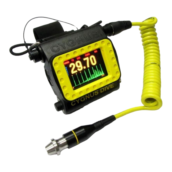
Cygnus Multiple Echo technique and Single Echo / Echo-Echo options. The Cygnus DIVE Underwater Thickness gauge is pressure rated to a maximum depth of 300 meters sea water (984 ft). The gauge can be worn on the diver’s fore-arm allowing one hand to remain free while carrying out the thickness survey. -
Page 8: Cygnus Instruments
Cygnus DIVE Operating Manual M3-DIVE-M-ENG_Iss9.docx Cygnus Instruments Cygnus Instruments Limited, founded in 1983, pioneered the development of the Digital Ultrasonic Multiple-Echo Technique used for measurement through coatings. This has long since been the standard required to ensure that accurate measurements are taken without the need to zero the gauge or remove any coatings first. -
Page 9: Gauge Kit Contents
The DIVE gauge is supplied as a complete kit in a tough Peli® transportation case. Everything you need to begin taking thickness measurements is included in the kit. 1. Cygnus DIVE Gauge Body and Wrist Strap 2. Ultrasonic Probe(s) with Coiled Cable 3. Two Rechargeable Batteries 4. -
Page 10: The Dive Gauge
Cygnus DIVE Operating Manual M3-DIVE-M-ENG_Iss9.docx 3. The DIVE Gauge Features of the DIVE Gauge Probe Connector Probe Connector (Cap Fitted) Right Button Left Button Colour Display Battery Battery Screw Left Side View showing Button, Battery & Probe Connector with Cap Fitted Right Side View showing Button, Battery Retaining Screw &... - Page 11 Cygnus DIVE Operating Manual M3-DIVE-M-ENG_Iss9.docx The Ultrasonic Probe is attached with a coiled cable allowing the diver to reach around structures when carrying out the survey. When not in use the probe can be easily secured to the strap by a loop and toggle using one hand.
- Page 12 Cygnus DIVE Operating Manual M3-DIVE-M-ENG_Iss9.docx Security Lanyard fitted to D ring. Page 12 of 117...
-
Page 13: Batteries
Cygnus DIVE Operating Manual M3-DIVE-M-ENG_Iss9.docx 4. Batteries Important Notes The battery MUST be fitted BEFORE the DIVE gauge is immersed into water. The battery MUST be removed when the DIVE gauge is no longer being used and/or stored in its Peli case. -
Page 14: Removing The Battery
Cygnus DIVE Operating Manual M3-DIVE-M-ENG_Iss9.docx The battery is secured with the battery retaining screw on the other end of the DIVE gauge body. Turn the battery retaining screw clockwise to engage the screw into the battery. Finger-tight only – the should be no gaps between the battery screw and the body. -
Page 15: Charging The Battery
Cygnus DIVE Operating Manual M3-DIVE-M-ENG_Iss9.docx Charging the Battery The battery must be charged using the supplied Cygnus battery charger and base. The battery is inserted into the charger base taking care to align the two battery contacts. The light on the black charging unit will... -
Page 16: Fitting The Ultrasonic Probe
Cygnus DIVE Operating Manual M3-DIVE-M-ENG_Iss9.docx 5. Fitting the Ultrasonic Probe Important – Cap Fitment The Cap must be fitted to the socket when it is not being used. Do not use the gauge with this socket exposed to water. Accidental removal of the Cap while underwater WILL NOT cause the gauge to flood. -
Page 17: Probe Calibration Check Message
Cygnus DIVE Operating Manual M3-DIVE-M-ENG_Iss9.docx The probe connector can be plugged into either of the connectors on the DIVE gauge body depending on which arm the DIVE gauge is worn on. The connector is a simple push-fit. The white dots must be aligned for the connectors to mate. -
Page 18: Securing The Probe While Diving
Cygnus DIVE Operating Manual M3-DIVE-M-ENG_Iss9.docx Securing the Probe while Diving You can secure the probe to the wrist strap using the loop and toggle, the probe can be secured and released with one hand. To secure the probe (if not already) press the toggle and push it back towards the gauge body to make the loop large. -
Page 19: Ultrasonic Probes (Transducers)
For more information see Measure Modes on page 28. Single Element Probes Cygnus pioneered the use of single element transducers and the multiple echo technique. Multiple Echo measurement offers the most reliable and accurate type of thickness measurement through coatings. -
Page 20: Twin Element Probes
Cygnus DIVE Operating Manual M3-DIVE-M-ENG_Iss9.docx Twin Element Probes Twin Element probes can be used to take thickness measurements on both Coated and Un-Coated metals. When measuring on Uncoated surfaces Single Echo mode can be used. Single Echo mode will also work best when measuring Heavy Corrosion –... -
Page 21: Probe Identification Band
Cygnus DIVE Operating Manual M3-DIVE-M-ENG_Iss9.docx Probe Identification Band Each probe also has a coloured band fitted to help identify the probe type and frequency. Probe Identification Bands Probe Frequencies As well as the two different probe types there are different frequencies available in each probe type. -
Page 22: Probe Measurement Ranges
Cygnus DIVE Operating Manual M3-DIVE-M-ENG_Iss9.docx Twin Element Probes Probe Type Details Applications Identification 3.5 MHz 13 mm Suitable for Orange Band (0.5”) measurement on thinner sections where surfaces are relatively rough 5.0 MHz 13 mm Ideal for thin sections Black Band (0.5”) - Page 23 Cygnus DIVE Operating Manual M3-DIVE-M-ENG_Iss9.docx Probe Type Measurement Range (in steel) 1.0 – 50 mm 0.04 – 2 inch The three letter Probe Type code can be easily decoded; Size 6mm (1/4 inch) ingle or 8mm (0.3 inch) Frequency in MHz...
-
Page 24: Probe Selection Chart
Cygnus DIVE Operating Manual M3-DIVE-M-ENG_Iss9.docx Probe Selection Chart Use this chart as a guide to selecting the right probe for your application. Probe Type Application Painted, coated & bare metals. Coatings up to 20mm (3/4in) thick Corrosion: non to moderate. -
Page 25: Single Element Probes And Protective Membranes
Single Echo mode. Single Element Probes and Protective Membranes All Cygnus single element probes have a soft face and are therefore fitted with a Polyurethane Membrane which provides better contact on rough surfaces and protects the probe face from wear, prolonging the life of the probe. -
Page 26: Changing The Protective Membrane On Single Element Probes
Cygnus DIVE Operating Manual M3-DIVE-M-ENG_Iss9.docx Changing the Protective Membrane on Single Element Probes Unscrew the Knurled Ring from the end of the Probe. Use the Membrane Key to unscrew the Locking Ring from inside the Knurled Ring. The old membrane can then be removed and discarded. -
Page 27: Automatic Probe Type Detection
Cygnus DIVE Operating Manual M3-DIVE-M-ENG_Iss9.docx Automatic Probe Type Detection The DIVE gauge can automatically determine the probe type when it is first connected to the gauge setting the appropriate parameters to suit the Probe Type. This feature will operate when the probe type is set to AUTO . -
Page 28: Measure Modes
This method has been used in all Cygnus gauges since the late 1970s. Multiple echo mode will ignore surface coatings (Through Coating mode) there is no need to remove the paint to take a measurement. -
Page 29: Echo-Echo Mode (Ee)
Cygnus DIVE Operating Manual M3-DIVE-M-ENG_Iss9.docx However single echo mode will not ignore any surface coatings, so if you measure through a coating it will give an incorrect metal thickness measurement. If the surface coating is very thin (0.2mm / 0.01”) paint you can make an allowance for this error, but thicker coatings introduce too much error to be practical. -
Page 30: Measuring Small Diameter Pipe & Tubes
Cygnus DIVE Operating Manual M3-DIVE-M-ENG_Iss9.docx the 2 echo is not within the expected region for a 2 echo then it is ignored and not used to give a thickness measurement. This check will help ensure Echo-Echo measurements are correct and discard any impractical measurements. -
Page 31: Why Should I Calibrate My Thickness Gauge
Cygnus DIVE Operating Manual M3-DIVE-M-ENG_Iss9.docx 8. Why should I Calibrate my Thickness Gauge? Ultrasonic thickness gauges measure time in order to measure the thickness of the material being tested. The rely on the principal that sound travels through a material at a constant velocity or speed. -
Page 32: Using The Dive Gauge
Turning the Gauge On Fitting a battery to the DIVE gauge will turn on the gauge. The gauge will display the Cygnus logo screen while it starts up. If the DIVE gauge has gone into standby mode then press and hold either button until the gauge turns on (this may take up to 5 seconds). -
Page 33: Zeroing The Probe (Twin Crystal)
Cygnus DIVE Operating Manual M3-DIVE-M-ENG_Iss9.docx Zeroing the Probe (twin crystal) If there is a twin crystal probe connected to the gauge you will be asked to perform a probe zero when the gauge is first turned Probe Zero Screen Simply wipe the probe face clean of any couplant and press either button to continue –... -
Page 34: Before Each Dive
Cygnus DIVE Operating Manual M3-DIVE-M-ENG_Iss9.docx Before Each Dive It is recommended you test the operation and calibration of the DIVE gauge before each dive. Follow these steps to ensure the equipment is functioning correctly: Generously smear silicone grease on the face of the... -
Page 35: The Measurement Screen
Cygnus DIVE Operating Manual M3-DIVE-M-ENG_Iss9.docx The Measurement Screen When the gauge is operating the measurement screen is displayed. Measure Probe Velocity of Mode Type Sound Measurement Battery Units Level Signal Strength Echo Bars Thickness Measurement A-Scan Value Display No Probe Connected Message When the probe is disconnected from the gauge a NO PROBE message is displayed. -
Page 36: Low Battery Level
Cygnus DIVE Operating Manual M3-DIVE-M-ENG_Iss9.docx Low Battery Level When the battery level is getting low the Battery Level indicator first turns Orange in colour. When the battery has less than 30 minutes life the Battery Level indicator turns Red and a Low Battery message is flashed at the top of the screen. -
Page 37: A-Scan Display In Single Echo Mode
Cygnus DIVE Operating Manual M3-DIVE-M-ENG_Iss9.docx When in Multiple Echo mode and a Multiple Echo verification has been found the three echo points are marked by three square boxes. When in Single Echo mode the echo point is marked by a single arrow below the X axis. - Page 38 Cygnus DIVE Operating Manual M3-DIVE-M-ENG_Iss9.docx Surface with barnacles removed Thin layers of green algae over paint don’t generally need to be removed. When using Multiple Echo mode you DO NOT need to remove any paint or surface protection – the gauge is designed to read through and ignore these layers.
-
Page 39: Taking A Thickness Measurement
Cygnus DIVE Operating Manual M3-DIVE-M-ENG_Iss9.docx Taking a Thickness Measurement Taking a Thickness Measurement Remove any marine growth, loose rust or loose coatings and brush the test area clean. When measuring underwater there is no need to use a couplant - the water itself will act as a couplant. -
Page 40: Echo Bars In Multiple Echo Mode
Cygnus DIVE Operating Manual M3-DIVE-M-ENG_Iss9.docx Echo Bars in Multiple Echo Mode Should the gauge be unable to detect a stable Multiple Echo signal it displays an echo bar indication to help the operator locate a suitable position. Multiple Echo Bars... -
Page 41: Stability Indication In Single Echo & Echo-Echo Modes
Cygnus DIVE Operating Manual M3-DIVE-M-ENG_Iss9.docx nearby surfaces, causing the echo bars to increase - this is normal. Stability Indication in Single Echo & Echo-Echo Modes To help indicate when a Single Echo or Echo-Echo measurement is stable – and thus probably reliable – the gauge changes... -
Page 42: Interpreting The A-Scan Display In Multiple Echo Mode
Cygnus DIVE Operating Manual M3-DIVE-M-ENG_Iss9.docx 10. Interpreting the A-Scan Display in Multiple Echo Mode The A-Scan display shows the actual ultrasound echo pulses as seen by the gauge, these echo pulses are used by the gauge to determine the thickness measurement if possible. -
Page 43: Pits And Flaws
Cygnus DIVE Operating Manual M3-DIVE-M-ENG_Iss9.docx The DIVE gauge uses negative ultrasound pulses to measure thickness, so the A-scan display shows Half Wave Negative Rectified signals. Pits and Flaws To obtain a reliable Multiple Echo thickness measurement the gauge must be able to see three distinguishable equi-spaced return echo pulses. -
Page 44: Heavy Corrosion
Cygnus DIVE Operating Manual M3-DIVE-M-ENG_Iss9.docx Now although the gauge is still correctly measuring 12.5mm you can see the echo pulses from the bottom of the blind hole (arrowed). In practice if you see smaller peaks between the larger peaks it could be indication of pits or flaws inside the material you are measuring. - Page 45 Cygnus DIVE Operating Manual M3-DIVE-M-ENG_Iss9.docx UT Probe 12.?mm Heavily Corroded Steel Sample. The best approach when having trouble getting Multiple Echo measurements is to try slowly moving the probe around the area looking for points where the echo pulses are stronger and more defined, keeping an eye on the A-scan so you spot “better”...
-
Page 46: Interpreting The A-Scan Display In Single Echo Mode
Cygnus DIVE Operating Manual M3-DIVE-M-ENG_Iss9.docx 11. Interpreting the A-Scan Display in Single Echo Mode The A-Scan display shows the actual ultrasound echo pulses as seen by the gauge, these echo pulses are used by the gauge to determine the thickness measurement if possible. -
Page 47: Measuring Over Corrosion Pits
Cygnus DIVE Operating Manual M3-DIVE-M-ENG_Iss9.docx This is an A-scan from a T2C probe measuring cast iron. This A-Scan shows a good clear ultrasound signal with a distinctive back-wall echo. Even though there are small echoes before Cast Iron the back-wall peak, the arrow is correctly placed under the start of the biggest echo peak. - Page 48 Cygnus DIVE Operating Manual M3-DIVE-M-ENG_Iss9.docx directly underneath the probe face as the gauge may incorrectly measure the depth of the couplant. Large Corrosion Pits. Couplant Probe Corroded Metal Avoid Measuring Directly Over Corrosion Pits. The A-Scan display can assist you - you will see a unclear ultrasound signal with no distinct back-wall echo.
-
Page 49: Interpreting The A-Scan Display In Echo-Echo Mode
Cygnus DIVE Operating Manual M3-DIVE-M-ENG_Iss9.docx 12. Interpreting the A-Scan Display in Echo- Echo Mode Just like Single Echo mode when measuring using Echo-Echo mode the A-Scan display can provide valuable information on the quality and reliability of and thickness measurement, and when no thickness measurement is given it can help the user understand why not. -
Page 50: Changing Gauge Settings
Cygnus DIVE Operating Manual M3-DIVE-M-ENG_Iss9.docx 13. Changing Gauge Settings The Two Button System The DIVE gauge only has two buttons – this means there are only three combinations to remember; • Left Button Press • Right Button Press • Both Buttons Pressed Together Both Buttons being pressed is generally used to Save &... -
Page 51: Button Functions In Setup Screens
Cygnus DIVE Operating Manual M3-DIVE-M-ENG_Iss9.docx Button Functions in Setup Screens Setup screens let you change a setting or value. For example changing the units between mm and inches. If you don’t press a button for 20 seconds the menu will automatically exit without saving any changes. -
Page 52: Displaying The Menu
Cygnus DIVE Operating Manual M3-DIVE-M-ENG_Iss9.docx Displaying the Menu To display the main Menu press the Left Button once. Measurement Screen Main Menu Screen Pressing the Left Button again will scroll down the Menu List one step each press. Pressing the Right Button will open the selected Item. -
Page 53: Menu Tree Diagram
Cygnus DIVE Operating Manual M3-DIVE-M-ENG_Iss9.docx Menu Tree Diagram The menu tree diagram shows the gauge’s menu items in the order they are displayed. Note some of the items are only displayed if that feature is enabled. Measurement Screen Displayed when;... -
Page 54: Data Logging Menu (Data Log Menu)
Cygnus DIVE Operating Manual M3-DIVE-M-ENG_Iss9.docx Data Logging Menu (DATA LOG MENU) For the DATA LOG MENU items refer to the section on Data Logging starting on page 66. A-Scan Range Setting (A-SCAN RANGE) The X-axis of the A-scan graph is ideally set to show the best number of return echoes in the material being measured. -
Page 55: Turning The A-Scan Display On Or Off (A-Scan Display)
Cygnus DIVE Operating Manual M3-DIVE-M-ENG_Iss9.docx 15 mm Range 30 mm Range 60 mm Range To change the A-Scan Range setting select A-SCAN RANGE from the Main Menu. Turning the A-Scan Display On or Off (A-SCAN DISPLAY) The A-Scan Display can be turned off if not required. -
Page 56: Calibrating To A Known Thickness (Calibrate)
Cygnus DIVE Operating Manual M3-DIVE-M-ENG_Iss9.docx Calibrating to a Known Thickness (CALIBRATE) This method of calibrating the gauge is more accurate than using a standard velocity value as the gauge calculates the velocity of sound for the sample material. You can use this calibration method for both Multiple and Single Echo modes. -
Page 57: Two Point Calibration (Calibrate 2 Point)
Cygnus DIVE Operating Manual M3-DIVE-M-ENG_Iss9.docx Calibrating to a Known Thickness echo bars. You must keep the probe on the measurement surface during calibration. Press Both Buttons to Save the calibrated thickness value and Exit. Two Point Calibration (CALIBRATE 2 POINT) The Two Point Calibration option is only available in Single Echo mode. -
Page 58: Two Point Calibration Procedure
Cygnus DIVE Operating Manual M3-DIVE-M-ENG_Iss9.docx Two Point Calibration Procedure Two Point Calibration Procedure First perform a Probe Zero function. Probe Zero Screen You must first determine the two calibration thicknesses you will be using. Then set these two thickness values in the gauge’s Calibrate 2 Point menu. -
Page 59: Zeroing The Twin Crystal Probe (Zero Probe)
Cygnus DIVE Operating Manual M3-DIVE-M-ENG_Iss9.docx Now you can perform the calibration. Select CALIBRATE 2 POINT from the menu Place the probe firmly on the thick calibration piece When the measurement displayed is stable press the Right button once Next place the probe firmly on the... - Page 60 Cygnus DIVE Operating Manual M3-DIVE-M-ENG_Iss9.docx If the probe gets significantly warmer during use this can cause a shift in the zero position and thus introduce small errors in the thickness measurement. Typically over a 20° C change in temperature the measurements can shift by 0.1 mm.
-
Page 61: Material Velocity Of Sound List (Material List)
Cygnus DIVE Operating Manual M3-DIVE-M-ENG_Iss9.docx Material Velocity of Sound List (MATERIAL LIST) The gauge holds a list of 8 common materials and their typical velocity of sound values; NO CHANGE MILD STEEL STAINLESS 302 STAINLESS 314 Material List Screen STAINLESS 316... -
Page 62: Measurement Units (Units)
Cygnus DIVE Operating Manual M3-DIVE-M-ENG_Iss9.docx Measurement Units (UNITS) The gauge can display the thickness measurement in mm or inches. To change the units select UNITS from the Main Menu. Changing the measurement units will not affect the calibration. Units Setup Screen... -
Page 63: Deep Coat Feature (Deep Coat)
Cygnus DIVE Operating Manual M3-DIVE-M-ENG_Iss9.docx Deep Coat Feature (DEEP COAT) In Multiple Echo mode with the Deep Coat OFF the gauge can measure through most protective coatings up to 3 mm (0.11”) thick, coatings like paint, anti-foul, hard plastics and epoxy should present no... -
Page 64: Probe Type Selection (Probe Type)
Cygnus DIVE Operating Manual M3-DIVE-M-ENG_Iss9.docx item and use the buttons to switch between Single Echo (SE) or Echo-Echo (EE) modes. Probe Type Selection (PROBE TYPE) The gauge can automatically detect the following probe types when the probe type is set to AUTO;... -
Page 65: Calibration Lock Feature
The gauge has the facility to lock the Velocity value, the Units and the Resolution settings. This feature can be used by a survey manager to prevent users from altering the calibration settings during a survey. To activate the Calibration Lock facility please contact Cygnus Instruments for instructions. Page 65 of 117... -
Page 66: Data Logging
A-scan graph, to the gauge’s internal memory. These measurements are then retrieved from the gauge by connecting to a computer which has Cygnus CygLink installed, the logged measurements are then transferred in to the computer and can be presented as a report, saved, emailed or exported to a spread-sheet application. -
Page 67: Grouping Measurements
Cygnus DIVE Operating Manual M3-DIVE-M-ENG_Iss9.docx After the set hold time the thickness measurement will be logged and the thickness measurement will flash to signal to the diver. The diver removes the probe from the surface for at least the set release time. -
Page 68: Starting A Data Logging Session (Start Logging)
Cygnus DIVE Operating Manual M3-DIVE-M-ENG_Iss9.docx The last 5 logged measurements logged and their ID number The total number of measurements logged and the current GroupID number Starting a Data Logging Session (START LOGGING) This function begins a new data logging session and starts logging measurements to the gauge’s memory, the GroupID... -
Page 69: Starting A New Group Of Measurements (Start New Group)
Cygnus DIVE Operating Manual M3-DIVE-M-ENG_Iss9.docx 1. Access the DATA LOG MENU 2. Select STOP LOGGING 3. Change from NO to YES 4. Press both buttons together to save and exit Stopped Message Starting a new Group of Measurements (START NEW... -
Page 70: Clearing The Data Logger Memory (Clear Memory)
Cygnus DIVE Operating Manual M3-DIVE-M-ENG_Iss9.docx 2. Select DELETE LAST 3. Change from NO to YES 4. Press both buttons together to delete and exit Deleted Message Clearing the Data Logger Memory (CLEAR MEMORY) You can delete all the measurements from the gauge’s memory ready to start a new... -
Page 71: Viewing The Data Logging Status (Data Logger Status)
Cygnus DIVE Operating Manual M3-DIVE-M-ENG_Iss9.docx Viewing the Data Logging Status (DATA LOGGER STATUS) The Data Logger Status screen shows the number of measurements taken and how many remain and the GroupID number. To view the status; 1. Access the DATA LOG MENU Data Logger Status 2. -
Page 72: Helmetview Remote Display
Cygnus DIVE Operating Manual M3-DIVE-M-ENG_Iss9.docx 15. HelmetView Remote Display HelmetView is an optional remote display that can be mounted on a Kirby Morgan ® dive helmet using an accessory screw. The display will show the measured thickness value or the echo bars just like the DIVE’s display. - Page 73 Cygnus DIVE Operating Manual M3-DIVE-M-ENG_Iss9.docx HelmetView Unit Fixed to Mounting Bracket The bracket is then fixed to the Kirby Morgan ® helmet using the left hand side accessory screw. The cable will exit to the rear of the helmet and the display will be visible in the top of the lens.
-
Page 74: Topside Repeater Remote Display Kit
2. Video Cables and DC Power Supply when supplied with Video Overlay option. You will also need a Umbilical cable and connectors to connect the DIVE gauge to the top side. Cygnus can supply the complete Page 74 of 117... -
Page 75: Operation
Turning the Unit On To turn on the TSR simply press the key with the Red Triangle, the Cygnus Logo screen will then be displayed. If not connected to a DIVE gauge the display shows “NO CONNECTION”. This is normal – it just means no data is being received yet. -
Page 76: Testing The Link
Cygnus DIVE Operating Manual M3-DIVE-M-ENG_Iss9.docx The Lemo connector plugs into the top of the Topside Repeater Display unit. Align the red marks on the plug and socket. Remove the blanking plug from the spare connector on the DIVE gauge. The plug on the umbilical plugs into the socket on the DIVE gauge. -
Page 77: Connecting The Video Signal
Cygnus DIVE Operating Manual M3-DIVE-M-ENG_Iss9.docx 28.10 5920 28.10 5920 The TSR with Video Overlay operates from an external DC power supply - there are no batteries required. Connecting the Video Signal The TSR has two BNC sockets on its top panel; Video In and Video Out. - Page 78 Cygnus DIVE Operating Manual M3-DIVE-M-ENG_Iss9.docx 28.10 5920 Setting On-Screen Display Position Press the MENU key to display the MENU. Press the DOWN ARROW key to scroll down to OSD X POS. Press EDIT to adjust the X screen position. Press EXIT to save and exit.
-
Page 79: Cyglink Surface Display And Control Kit
2. CygLink Software Installer on USB Flash Drive You will also need an Umbilical cable and connectors to connect the DIVE gauge to the top side. Cygnus can supply the complete umbilical cable with connectors fitted, or the customer can make their own umbilical cable using connectors supplied with cable tails. -
Page 80: Connection Diagram
Cygnus DIVE Operating Manual M3-DIVE-M-ENG_Iss9.docx Connection Diagram Computer with CygLink USB-RS485 Converter Umbilical Cable 1 twisted pair + screen (500m maximum length) DIVE Gauge Connector Details and Signals See Connection s from page 113 Using CygLink with HelmetView As HelmetView and CygLink both need to connect to the spare connector on the gauge a “Y”... -
Page 81: Installing Cyglink
Installing CygLink CygLink V5 is supplied with the kit on a USB Flash Drive, or it can be downloaded from the Cygnus Instruments website. If you want to make sure you are installing the latest version then downloading from the website is the best route. -
Page 82: Com Port Numbers
Cygnus DIVE Operating Manual M3-DIVE-M-ENG_Iss9.docx COM Port Numbers CygLink should automatically find the COM port number assigned to the USB converter when you click “connect” so you don’t need to search for the port number Windows has assigned. Setting the COM Port Manually If CygLink fails to locate the correct COM port number you can set in manually from the File ->... -
Page 83: Connecting To The Gauge
Cygnus DIVE Operating Manual M3-DIVE-M-ENG_Iss9.docx Connecting to the Gauge First time USB Connection When you first connect the gauge to the computers USB port Windows will search for a suitable driver, you may notice this message from the taskbar; If you click the message you should see the driver installation process;... -
Page 84: Connecting The Gauge To Cyglink For The First Time
Cygnus DIVE Operating Manual M3-DIVE-M-ENG_Iss9.docx Connecting the Gauge to CygLink for the First Time Turn on the gauge Run CygLink V5 From the Menu click; Connect └ Discover new Gauge and Connect CygLink will search all the available Com ports listening for a Cygnus gauge.. -
Page 85: Connecting To The Gauge Afterwards
Cygnus DIVE Operating Manual M3-DIVE-M-ENG_Iss9.docx Connecting to the Gauge Afterwards Once you have discovered the Gauge the connection settings will be stored for next time, so to connect next time simply click from the menu; Connect └ Connect to Mx-DIVE Gauge... -
Page 86: Changing Gauge Settings
Cygnus DIVE Operating Manual M3-DIVE-M-ENG_Iss9.docx Changing Gauge Settings To change the gauge settings click Gauge -> Measurement Settings. You can change the Units, Measurement mode, Velocity, Deep Coat and A-Scan Range. Any changes will be sent to the gauge and also update CygLink. -
Page 87: A-Scan Measurement Cursors
Cygnus DIVE Operating Manual M3-DIVE-M-ENG_Iss9.docx A-Scan Measurement Cursors The A-Scan display can be frozen to make measurements using two cursors easier, nut is not necessary to take a measurement. To freeze the display click the Freeze button. To display the cursors click the Cursors button, to move the cursors left click and hold at the cross wire intersection. -
Page 88: Cyglink Surveys And Data Logging
Cygnus DIVE Operating Manual M3-DIVE-M-ENG_Iss9.docx when using the cursor to estimate thickness measurements from twin crystal probes be aware that the estimated value could be larger than the actual thickness. CygLink Surveys and Data Logging CygLink have the facility to store logged thickness measurements in a single Survey file. -
Page 89: Editing The Survey Details
Cygnus DIVE Operating Manual M3-DIVE-M-ENG_Iss9.docx File Menu. Editing the Survey Details The Survey contains all the Groups and is used to save all the data. You can also add details to the Survey that will be printed at the beginning of the PDF report. -
Page 90: Editing The Survey Group Details
Cygnus DIVE Operating Manual M3-DIVE-M-ENG_Iss9.docx Editing the Survey Group Details To view and edit the survey Group details right click on the records number and select properties. To create a new Survey Group select in the File menu New Survey Record. -
Page 91: Transferring Data Logged Measurements From The Dive Gauge
Cygnus DIVE Operating Manual M3-DIVE-M-ENG_Iss9.docx Transferring Data Logged Measurements from the DIVE gauge You can transfer all the Data Logged measurements from a connected DIVE gauge into the CygLink Survey. From the menu select Gauge then Transfer Records from Gauge, you will then need to confirm the action;... -
Page 92: Logging Measurements Directly In Cyglink
Cygnus DIVE Operating Manual M3-DIVE-M-ENG_Iss9.docx Each group of measurements in the DIVE gauge will be transferred into a new Survey Group in CygLink. If you repeat the transfer a second time, the measurements will be appended to the Survey again in new Survey Groups. -
Page 93: Adding Comments Or Notes To A Measurement
Cygnus DIVE Operating Manual M3-DIVE-M-ENG_Iss9.docx Measurement Comments Screen. Adding Comments or Notes to a Measurement You can add your own quick text Notes to any logged thickness measurement, just select the measurement point in the list and right click to display more options. -
Page 94: To Change The Com Port Number Assigned By Windows
Cygnus DIVE Operating Manual M3-DIVE-M-ENG_Iss9.docx To Change the COM Port number assigned by Windows ® Depending on a variety of factors, Windows ® may sometimes assign a COM Port number that is too high or unusual to be easily remembered. You may change the number assigned to the port by... -
Page 95: Cyglink Trouble Shooting
Cygnus DIVE Operating Manual M3-DIVE-M-ENG_Iss9.docx 3. On the “Advanced Settings” form you can change the COM Port number. Finish by clicking the “OK” button. CygLink Trouble Shooting Connection Problems – USB Drivers If you are unable to get a connection the first thing to try is updating the USB drivers for the Serial to USB converter. -
Page 96: Wiring Problems
Cygnus DIVE Operating Manual M3-DIVE-M-ENG_Iss9.docx Type this into Google search “FTDI USB RS485 Cable” Or follow this link directly to the FTDI website; http://www.ftdichip.com/Products/Cables/USBRS485.htm Click on the VCP Drivers link; You will see a table of drivers with the most recent at the top. The x86 (32bit) driver is recommended. -
Page 97: General Points On Thickness Gauging Using Multiple Echo Measurements
Cygnus DIVE Operating Manual M3-DIVE-M-ENG_Iss9.docx 18. General Points on Thickness Gauging using Multiple Echo Measurements On very rough surfaces and especially if both sides are badly corroded, it is often necessary to move the probe around to locate a back wall reflector. Sometimes a slight rocking movement can help find reflectors which are otherwise impossible to detect. -
Page 98: Care And Servicing
Cygnus DIVE Operating Manual M3-DIVE-M-ENG_Iss9.docx 19. Care and Servicing Cleaning the Gauge After each dive while the gauge is still assembled, wash the unit in fresh water and allow to dry. Do not use solvents to clean the gauge. Do not use any abrasive cleaner, especially on the display window. -
Page 99: Repairs
M3-DIVE-M-ENG_Iss9.docx Repairs There are no user serviceable parts inside the gauge. Therefore all repair work should be carried out by Cygnus Instruments or by an Authorised Cygnus Service dealer. Returning the Gauge for Servicing A full Manufacturer’s Factory Service is available from Cygnus Instruments. -
Page 100: Replaceable Parts
M3-DIVE-M-ENG_Iss9.docx 20. Replaceable Parts Wrist Strap The Wrist Strap may be easily removed and replaced and Cygnus can provide a wrist strap replacement kit (see page 101). Four grub screws secure the wrist strap locating pins in place, to remove the pins unscrew the two grub screws on one side only using a 1.5mm hex drive or Allen key. -
Page 101: Spares And Accessories List
Probe and coiled cable, spare membranes and membrane key. Suitable for measuring small tubes from 1 to 50mm through very thin coatings. 001-7235 Probe T5B 5MHz 2 x 8mm for Cygnus DIVE Probe and coiled cable, Suitable for measuring heavy corrosion from 1.5 to 50mm.. 001-7236... -
Page 102: Gauge Spares
RS485 to USB. 1.8m Long 001-0426 Umbilical (9-way D) to TSR Display Unit (Lemo) Link Lead Connects surface end of Umbilical Cable (001-7260) to a Cygnus TSR. 1.0m Long 001-7264 Cygnus DIVE Gauge to Umbilical Splice Cable Connects to DIVE gauge with flying lead for splice in to customers own Umbilical Cable. -
Page 103: Miscellaneous Spares
CygLink software on USB Flash Drive. Umbilical to computer link lead & Cygnus DIVE to Top-Side umbilical connectors and data converters. 001-7260 Cygnus DIVE (Fischer)-(9-way D) Topside umbilical connectors Add to 001-7221/4, 001-7222/4 or 001-7223 for Cygnus supplied umbilical cable. 001-0415 Umbilical cable for DIVE to Topside (per metre) Specify cable length from 50m to 500m. -
Page 104: Technical Specifications
Cygnus DIVE Operating Manual M3-DIVE-M-ENG_Iss9.docx 22. Technical Specifications Cygnus DIVE Technical Specifications General Attributes Size 105 mm x 110 mm x 35 mm (W x H x D) (4.1 in x 4.3 in x 1.4 in) Weight In Air Complete Gauge 905 g (2 lb.) Gauge Body 557 g (1.22 lb.) - Page 105 Cygnus DIVE Operating Manual M3-DIVE-M-ENG_Iss9.docx Cygnus DIVE Technical Specifications Measurement Range Measurement Ranges in Steel Multiple Echo mode; S2C probe 3 to 250 mm [0.120 in. to 10.00 in.] S3C probe 2 to 150 mm [0.080 in. to 6.000 in.]...
- Page 106 UKCA An EU and UK Decleration of Conformity is supplied with the product kit. Designed for BS EN 15317 The Cygnus DIVE gauge is a European Registered Community Design, No. 001947326-0001. See http://oami.europa.eu for more details. Page 106 of 117...
-
Page 107: Table Of Sound Velocities
Cygnus DIVE Operating Manual M3-DIVE-M-ENG_Iss9.docx 23. Table of Sound Velocities Velocities will vary according to the precise grade and processing conditions of the material being measured. This table is included as a guide only. Wherever possible, the Gauge should always be calibrated on the material under test. -
Page 108: Reading Conversions
Cygnus DIVE Operating Manual M3-DIVE-M-ENG_Iss9.docx Velocity of Sound (V) Conversion Material Factor (f) in/us Stainless Steel 316 5750 0.2264 0.971 F51 Duplex Steel 0.956 – 5715 - 5750 0.225 – 0.2264 UNS S31803 0.971 Core Ten Steel 5920 0.2331 1.00... -
Page 109: Recycling And Disposal (Ec Countries)
Cygnus DIVE Operating Manual M3-DIVE-M-ENG_Iss9.docx 24. Recycling and Disposal (EC Countries) The WEEE Directive (Waste Electrical and Electronic Equipment 2002/96.EC) has been put into place to ensure that products are recycled using best available treatment, recovery and recycling techniques to ensure human health and high environmental protection. -
Page 110: Shipping Of Lithium-Ion Batteries
Criteria, Part III, subsection 38.3. For shipping they must be packaged as set out in IATA Packaging Instructions 966. Faulty batteries MUST NOT be shipped back to Cygnus Instruments, their agent or distributor. It is forbidden to transport faulty or damaged lithium batteries, they must be correctly disposed of locally. -
Page 111: Warranty Information
6. Except in respect of death or personal injury caused by the negligence of Cygnus, Cygnus shall not be liable to the Purchaser or to any other person by reason of any representation (unless fraudulent), or any implied warranty, condition or other term,... -
Page 112: Pressure Test Statement
Cygnus DIVE Operating Manual M3-DIVE-M-ENG_Iss9.docx 27. Pressure Test Statement All Cygnus DIVE gauges are pressure tested in water as part of our test procedures. Please refer to the environmental rating section for further information Page 112 of 117... -
Page 113: Connection Diagram: Umbilical Cable
Cygnus DIVE Operating Manual M3-DIVE-M-ENG_Iss9.docx 28. Connection Diagram: Umbilical Cable Page 113 of 117... -
Page 114: Connection Diagram: Umbilical To Tsr
Cygnus DIVE Operating Manual M3-DIVE-M-ENG_Iss9.docx 29. Connection Diagram: Umbilical to TSR Page 114 of 117... -
Page 115: Connection Diagram: Dive To Umbilical
Cygnus DIVE Operating Manual M3-DIVE-M-ENG_Iss9.docx 30. Connection Diagram: DIVE to Umbilical Page 115 of 117... -
Page 116: Index
Cygnus DIVE Operating Manual M3-DIVE-M-ENG_Iss9.docx 31. Index A-Scan AutoLog, 66 Backwall Echo, 42, 46 AutoLog RELEASE, 71 Pits & Flaws, 43 Capacity, 66 A-Scan Display Clearing Memory, 70 Range, 54 Grouping, 67 Turning On/Off, 55 Groups, 69 Battery Stop, 68... - Page 117 Cygnus DIVE Operating Manual M3-DIVE-M-ENG_Iss9.docx Recycling, 109 Through Coating, 28 Repair, 99 Topside Repeater Serial Number, 32 Automatic Display Backlight, Service, 99 Setup Screens, 51 Batteries, 76 Single Echo, 28 Display Units, 75 Resolution, 62 HOLD, 75 Software Version, 32...
Need help?
Do you have a question about the M3-DIVE and is the answer not in the manual?
Questions and answers