
Summary of Contents for FLIR Raymarine AIS5000
- Page 1 AIS5000 Installation and operation instructions English Date: 06-2019 Document number: 81383-5 © 2019 Raymarine UK Limited...
- Page 3 List of abbreviations List of abbreviations Automatic Identification System AIS SART AIS Search and Rescue Transmitter Access Point (Relating to WiFi behaviour) AtoN AIS Aid to Navigation Compact Disc European Declaration of Conformity Course Over Ground Common (electrical) Closest Point of Approach Carrier Sense Direct Current Decimal...
- Page 4 List of abbreviations Estimated Time of Arrival External Federal Communications Committee GNSS satellite fault detection message GNSS fix accuracy and integrity message Global positioning system (GPS) fix data message Geographic position - Latitude/longitude message GLONASS Globalnaya Navigazionnaya Sputnikovaya Sistema (Russian GNSS) Electrical Ground GNSS fix data message...
- Page 5 List of abbreviations Latitude Liquid Crystal Display Longitude Long Range Minimum Keyboard and Display MMSI Maritime Mobile Service Identity Man Overboard Normally Closed (electrical) Navigation Nautical Miles NMEA National Marine Electronics Association Portable Document Format Parameter Group Number Presentation Interface RAIM Receiver Autonomous Integrity Monitoring Radio Equipment Directive...
- Page 6 List of abbreviations TCPA Time to Closest Point of Approach TDMA Time Division Multiple Access True heading and status message Threaded Neill–Concelman (a type of connector) Threads per Inch Transmit User Datagram Protocol Ultra High Frequency Co-ordinated Universal Time Dual ground/water speed message All VDL AIS messages received AIS own-ship broadcast data Very High Frequency...
-
Page 7: Table Of Contents
Table of contents Table of contents Notices ............11 Safety warnings ................11 General notices................12 Regulatory statements ..............13 Introduction ............19 About AIS..................19 Installation and configuration.......21 What’s in the box? ................. 21 Preparing for installation ..............21 Installation procedures..............22 Connecting the equipment ............. - Page 8 Table of contents 4.10 Communication test ............... 59 4.11 Displaying AIS targets..............60 4.12 Micro SD card data input..............62 4.13 WiFi Feature................... 64 STEDS mode ..........67 STEDS Operation ................67 STEDS Presentation interface ............69 Technical information........71 Interface circuits ................71 Output drive capability of bi-directional ports .........
- Page 9 Table of contents Technical specification........95 Applicable equipment standards............ 95 Product category................96 Physical..................96 Environmental ................97 Electrical ..................97 Display and user interface ............. 97 Internal GNSS................99 TDMA Transmitter................99 TDMA Receiver................99 8.10 DSC Receiver ................100 8.11 RF Connections ................
- Page 10 Table of contents Page 8...
- Page 11 List of figures and tables List of figures and tables Table 1 MED Compliance Matrix ............14 Figure 1 The AIS network ..............19 Figure 2 What’s in the box? ............... 21 Figure 3 Typical AIS transceiver connection........23 Figure 4 Mounting the AIS transceiver..........
- Page 12 List of figures and tables Figure 27 Input port schematic............. 71 Figure 28 Data output port schematic ..........72 Figure 29 AIS Transceiver dimensions ..........74 Figure 30 GNSS Antenna ..............75 Table 9 IEC61162 Transmission interval for periodic sentences..76 Table 10 IEC61162 Sentences input and output ........
-
Page 13: Notices
Notices Notices When reading this manual please pay particular attention to warnings marked with the warning triangle symbol shown on the left. These are important messages for safety, installation and usage of the AIS transceiver. 1.1 Safety warnings This equipment must be installed in accordance with the instructions provided in this manual. -
Page 14: General Notices
Notices Do not attempt to service this equipment as doing so may cause fire, electric shock or malfunction and will invalidate the warranty. If any malfunctions are detected contact your supplier or service agent. NOT ALL SHIPS CARRY AIS. The Officer of the Watch should always be aware that other ships and, in particular, leisure craft, fishing vessels and warships may not be fitted with AIS. -
Page 15: Regulatory Statements
Notices electrical equipment. Please dispose of the packaging in an environmentally friendly manner. 1.2.6 Accuracy of this manual This manual is intended as a guide to the installation, setup and use of this product. If you are in any doubt about any aspect of this product, please contact your dealer. - Page 16 Notices IMO Resolutions International Testing Standards IMO Res. MSC 74(69) IEC 61993-2 Ed.2 (2012) Maritime navigation and ITU-R M. 1371-5 (2014) radiocommunication equipment and systems - Automatic identification IMO Res. A.917(22) systems (AIS) Part 2: Class A shipborne equipment of the IMO Res.
- Page 17 Notices 1.3.4 Quality Standards This product has been developed and manufactured under a certified ISO9001:2008 Quality Management System (BSI certificate number FS548550). The following quality standards apply to the product: ANSI-Z1.4 - Sampling Procedures and Tables for Inspection by Attributes. ANSI/NCSL Z540.3-2006, Requirements for the Calibration of Measuring and Test Equipment.
- Page 18 Notices 1.3.5 FCC Notice This equipment has been tested and found to comply with the limits for a class A digital device, pursuant to part 15 of the FCC Rules. These limits are designed to provide reasonable protection against harmful interference in a residential installation. This equipment generates, uses and can radiate radio frequency energy and, if not installed and used in accordance with the instructions, may cause harmful interference to radio communications.
- Page 19 Notices 1.3.6 Industry Canada Notice This device complies with Industry Canada licence-exempt RSS standard(s). Operation is subject to the following two conditions: 1.This device may not cause interference, and 2.This device must accept any interference, including interference that may cause undesired operation of the device. This Class A digital apparatus complies with Canadian ICES-003.
- Page 20 Notices Page 18...
-
Page 21: Introduction
Introduction Introduction 2.1 About AIS The marine Automatic Identification System (AIS) is a location and vessel information reporting system. It allows vessels equipped with AIS to automatically and dynamically share and regularly update their position, speed, course and other information such as vessel identity with similarly equipped vessels. - Page 22 Introduction Page 20...
-
Page 23: Installation And Configuration
Installation and configuration Installation and configuration 3.1 What’s in the box? Please ensure all items are present and if any of the items are missing please contact your dealer. Warranty card Product mounting AIS transceiver Product template manual Quick start guide Product CD Mounting bracket... -
Page 24: Installation Procedures
Installation and configuration 3.2.1 VHF Antenna Connection of a suitable VHF antenna will be required for the AIS transceiver to operate. The antenna cable should be terminated with a PL-259 (or UHF) connector. A surge arrestor should be fitted in line with VHF antenna connector. - Page 25 Installation and configuration VHF antenna GNSS antenna Surge arrestor Above decks Below decks 12V DC to 24V DC Supply Chassis/GND Optional connections NMEA2000 Displays Ship’s sensor data (DGPS, GYRO, Heading) (ECDIS, Radar) Figure 3 Typical AIS transceiver connection Page 23...
- Page 26 Installation and configuration 3.3.1 Step 1 - Installing the AIS transceiver Please note the following guidelines when selecting a location for your AIS transceiver: ● The AIS transceiver must be fitted in a location where it is at least 0.5m (1ft 8ins) from a compass or any magnetic device. ●...
- Page 27 Installation and configuration Panel mounted Desk mounted Overhead mounted (reverse mounting bracket) Figure 4 Mounting the AIS transceiver Refer to Figure 29. for dimensions. A drilling and cutting template is provided with the AIS transceiver. To panel mount the unit it is necessary to remove the 4 off socket cap screws recessed in front of the unit.
- Page 28 Installation and configuration Figure 5 Desk mounting the AIS transceiver Page 26...
- Page 29 Installation and configuration Figure 6 Panel mounting the AIS transceiver 3.3.2 Installing the GNSS antenna For mounting the GNSS antenna supplied with your AIS transceiver you will require a one inch 14 TPI pole mount. Contact your dealer to source a mount suitable for the installation location.
- Page 30 Installation and configuration ● The GNSS antenna should be located where it has a clear, unobstructed view of the sky overhead. ● The GNSS antenna should be mounted as high as possible, however it is not recommended to mount the antenna on the top of a high mast where the motion of the vessel will cause the antenna to move and potentially reduce the accuracy of the GNSS position.
- Page 31 Installation and configuration GNSS Antenna connection Figure 8 GNSS Antenna connection 3.3.3 Installing the VHF antenna Please note the following guidelines when selecting and locating the AIS VHF antenna: ● The VHF antenna should be located as high as possible and positioned as far from other antennas as possible.
- Page 32 Installation and configuration ● The VHF antenna cable should be kept as short as possible to minimize signal loss. High quality, low loss co-axial cable appropriate to the installation location should be used. ● The VHF antenna cable should be terminated in a PL-259 co-axial connector for connection to the AIS transceiver.
-
Page 33: Connecting The Equipment
Installation and configuration VHF antenna connection Figure 10 VHF Antenna connection 3.4 Connecting the equipment 3.4.1 Data connections The AIS transceiver is supplied with a 2m (6.5 ft) 18 way data cable and a 2m (6.5 ft) 14 way data cable for connection of the AIS transceiver to external sensors and equipment. - Page 34 Installation and configuration 3.4.3 Data input ports (14 way connector) 14 way interface connection Figure 11 Serial input port connection Page 32...
- Page 35 Installation and configuration SIGNAL WIRE COLOUR BLUE SIGN N BLACK BLUE SIGN P BROWN SILENT N BLUE SILENT P SENSOR 1 RX B ORANGE SENSOR 1 RX A PURPLE GREEN SENSOR 1 COM SENSOR 2 RX B WHITE SENSOR 2 RX A WHITE / BLACK GREY SENSOR 2 COM...
- Page 36 Installation and configuration Note: Any unused ports should be terminated by a 120 Ohm resistor across RX A and RX B signals. 3.4.4 Silent mode switch To activate the Silent mode switch, apply a voltage of between 2V and 30V to the SILENT P (Pin 7) and SILENT N (Pin 6) terminals of the 14 way connector.
- Page 37 Installation and configuration 3.4.5 Data bi-directional ports (18 way connector) 18 way interface connection Figure 14 Serial bi-directional port connection Page 35...
- Page 38 Installation and configuration SIGNAL WIRE COLOUR LR DGPS TX B ORANGE LR DGPS TX A BROWN 15 14 LR DGPS RX B PURPLE LR DGPS RX A BLUE 11 10 LR DGPS COM BLACK PILOT TX B PILOT TX A RED / WHITE PILOT RX B PINK...
- Page 39 Installation and configuration Note: Any unused ports should be terminated by a 120 Ohm resistor across RX A and RX B signals. COMMON signals should be grounded. All sensor ports can be configured via the Interface settings menu which can be found under the ‘Home’...
- Page 40 Installation and configuration 3.4.7 Power connection Power is connected to the AIS transceiver via the supplied 2 way power cable as shown in Figure 16. Power connection Figure 16 Power connection Wire colour Function Connect to Power supply + 12VDC to 24VDC power supply from ships emergency power source* Black...
-
Page 41: Grounding The Ais Transceiver
Installation and configuration *Connection to an emergency power source is an IMO requirement for SOLAS vessels. The power supply current ratings and recommended fusing or circuit breaker currents are as follows: ● A 12VDC supply should be able to provide a peak current of 4.3A and be fused at 10.0A. -
Page 42: Connection To An Nmea2000 Network (Optional)
Installation and configuration This product must be connected to protective ground via the ground connection point. It is essential that the ground connection point is used in all installations, regardless of what other equipment is connected. The ground connection point must be bonded to protective ground using as short a connection as possible. -
Page 43: Turning The Ais Transceiver On
Installation and configuration If the USB connection is removed from the PC or Mac during use you must reset the connection before further use. To reset the connection, disconnect then reapply power to the AIS before closing and relaunching any PC or Mac applications using the USB connection. - Page 44 Installation and configuration Following configuration of the AIS transceiver the password should be changed from its default value of ‘0000’ (four zeros) to another alpha numeric code. Password change is carried out by selecting ‘Home’ > ‘System settings’ > ‘User Settings’ > ‘Password’. The password should be recorded on the installation record found in Section 9.
-
Page 45: Operation
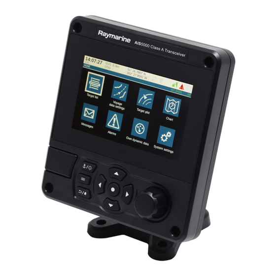
Operation Operation Please read the warning notices at the front of this manual before operating the AIS transceiver. 4.1 Display and controls Navigation status / Screen brightness Display Select Micro SD card slot behind door Options menu Back / Home Scroll wheel Function keys (push to select) -
Page 46: Button Functions
Operation 4.2 Button functions Scroll wheel. This is used to highlight information presented on the display. The scroll wheel can also be pressed to confirm data entry or select information. Navigation status / Screen brightness key. When pressed with a short press will go to the Navigation status screen. -
Page 47: Changing Navigation Status
Operation When in this mode it is possible to switch off the screen via a single, long press on the 'Select' key. A press of any button restores the screen to its default brightness. Whilst the screen is switched off all internal functions of the AIS transceiver continue to operate as normal. - Page 48 Operation 4.5.1 Main / Sub menus Menus are displayed as a set of icons which can be navigated by using the controls. Selection of an icon will then display the information beneath in accordance with Figure 21. Pressing the ‘Back / Home’ key will exit the menu. Page 46...
- Page 49 Operation HOME INBOX TARGET LIST SENT VOYAGE DATA SETTINGS COMPOSE TARGET PLOT CHART* MESSAGES DISPLAY & UNIT SETTINGS ALARMS SOUND SETTINGS LANGUAGE OWN DYNAMIC DATA TIME SYSTEM SETTINGS PASSWORD FILTER AND CPA/TCPA SETTINGS USER SETTINGS INTERFACES SENSOR PORT 1 SENSOR PORT 2 SYSTEM INFORMATION ADVANCED SENSOR PORT 3...
-
Page 50: Information Displayed
Operation 4.5.2 Data entry screens Some screens allow you to enter data, such as vessel parameters. On these screens you navigate to the desired field and select the appropriate menu item. Some data entry items require a password, this is shown by means of a ‘Padlock’... - Page 51 Operation 4.6.1 Menu title Refers to the current menu displayed from Figure 21. 4.6.2 Time Time derived from GNSS satellites or AIS Base Stations. 4.6.3 Time offset Offset from UTC, set on the ‘Time’ menu. 4.6.4 Speed / Course Vessel speed and course as taken from GNSS satellite data. 4.6.5 Position Vessel position taken from GNSS source.
- Page 52 Operation Icon Description Shown when the transmitter is set to 1W mode. INT GNSS Shown when the internal GNSS receiver has a valid position fix. EXT GNSS Shown when the connected external GNSS receiver has a valid position fix. NO GNSS Shown when there is no valid internal or external position fix.
- Page 53 Operation on-screen message. The list of currently active AIS Alarms can be displayed by accessing the ‘Alarms’ menu. If any alarm condition persists, contact your dealer or installer. Possible alarm conditions are listed Table 7. Alarm Description TX Malfunction This alarm will occur if the MMSI has not been configured.
- Page 54 Operation Alarm Description No valid COG information This alarm occurs if the AIS transceiver has no valid Course Over Ground information from any connected sensor. No valid SOG information This alarm occurs if the AIS transceiver has no valid Speed Over Ground information from any connected sensor.
- Page 55 Operation Alarm Description Active AIS SART An active AIS SART (AIS Search and Rescue Transmitter) message has been received. The SART will be displayed as the top item in the target list. Select this item to see the location of the SART. Internal / External GNSS This alarm occurs if the difference in position mismatch...
- Page 56 Operation AIS messages can be viewed, created and transmitted from the ‘Messages’ menu. The available options are: Compose - takes you to the message composition screen Inbox - takes you to the received message list view Sent - shows a list of recently sent messages. To compose a new message, select the type of message from the drop down menu and the destination.
- Page 57 Operation 4.6.10 Chart The Chart feature is only enabled when this Class A AIS transceiver is operating on a non-SOLAS vessel. The AIS transceiver contains an application which will display AIS targets received, along with its own vessel position on a chart style plot. The chart can be scrolled up, down, left, and right using the ‘Function’...
-
Page 58: Configuring Vessel Information
Operation 4.7 Configuring vessel information 4.7.1 Pre-configuration checks To proceed with configuration the steps in Section 3 should already have been completed. 4.7.2 Configuring vessel identification information The AIS transceiver must be configured with information about the vessel on which it is installed prior to operation. The following information is required to be entered in the ‘Home’... - Page 59 Operation The operating mode can be selected from the ‘GNSS source’ option in the ‘Home’ > ‘System settings’ > ‘Advanced’ settings menu. The antenna dimensions should be entered in metres according to the diagram provided in Figure 23. GNSS Antenna Ref C Stern Ref B...
-
Page 60: Configuring Voyage Information
Operation 4.8 Configuring voyage information 4.8.1 Configure voyage related data The AIS transceiver must be configured with information about its voyage prior to operation. To enter the vessel identification information select the ‘Home’ > ‘Voyage Data settings’ option. The following information is required: ●... -
Page 61: Communication Test
Operation The AIS transceiver is now operational and should remain powered unless authorised by the local maritime authority. The installation record at the rear of this manual should be completed and left on board the vessel. 4.10 Communication test It is possible to conduct an AIS communication test with another AIS equipped vessel. -
Page 62: Displaying Ais Targets
Operation 4.11 Displaying AIS targets 4.11.1 Target list The ‘Target list’ screen is the primary screen for displaying AIS targets received. This is the first screen displayed when the unit is switched on, but can also be accessed from the ‘Target list’ option on the ‘Home’ menu. 16:58:29 SOG 21.1kt 50°... - Page 63 Operation Different symbols are shown for an AIS target depending on the type of target and its status, these are shown in Figure 25. These symbols are common to the ‘Target list’ and ‘Target plot’ displays. Base station Virtual AIS AtoN AIS Class A AIS Class B AIS SART...
-
Page 64: Micro Sd Card Data Input
Operation These CPA/TCPA figures are calculated solely on AIS data and should not be used for anti-collision purposes. Note: Setting the CPA/TCPA filter will not activate the Filters Icon. 4.11.4 Target plot The ‘Target plot’ screen shows the location of other AIS equipped vessels and shore stations relative to your own vessel. - Page 65 Operation Figure 26 Micro SD card Socket 4.12.1 Loading new charts The AIS transceiver always contains a basic low resolution world chart. More detailed resolution charts can be purchased and overlaid onto the AIS transceiver’s chart display. The AIS transceiver will read only C-MAP MAX format Micro SD cards. See your dealer for available charts for your region.
-
Page 66: Wifi Feature
Operation 4.12.2 Upgrading the unit firmware If a Micro SD card that contains valid upgrade firmware is inserted into the card socket, the unit will recognize the new firmware and will display a message asking you if you want to install it. The system will guide you to the appropriate menu screen, where the firmware update can be applied. - Page 67 Operation output a range of NMEA0183 sentences over the selected WiFi port to any connected devices. 4.13.2 Access point mode If the AIS transceiver is configured as a WiFi access point (AP) it will create its own WiFi network, allowing other WiFi enabled devices to connect to it. Up to 5 simultaneous connections are supported.
- Page 68 Operation Page 66...
-
Page 69: Steds Mode
STEDS mode STEDS mode 5.1 STEDS Operation 5.1.1 STEDS operating modes When STEDS operation is enabled the AIS Transceiver may operate in the following modes: ● Receive Only ● Normal Transmit ● Restricted Transmit In Receive-Only, all broadcast and own-vessel addressed AIS messages received over the standard AIS VDL channels shall be reported via the presentation interface. - Page 70 STEDS mode Presentation Presentation Transmit Type Period Timeout Period Access (seconds) (seconds) (seconds) Method ITDMA ITDMA ITDMA On demand RATDMA On demand On demand RATDMA On demand On demand RATDMA SITREP 15/30 (SOG ITDMA dependant) Static On demand RATDMA Data Other On demand On demand...
-
Page 71: Steds Presentation Interface
STEDS mode 5.2 STEDS Presentation interface 5.2.1 Operating mode configuration and reporting The STEDS operating mode may be set by any of the following means: ● "PUCG,STEDS propriatary sentence on the NMEA 0183 PI ● "PGN# 65535 on the NMEA 2000 PI The following means are supported also for compatibility with legacy systems: ●... - Page 72 STEDS mode Page 70...
-
Page 73: Technical Information
Technical information Technical information 6.1 Interface circuits 6.1.1 Sensor data input port The sensor data input port schematic is shown in Figure 27. V ISOOUT DC to DC Converter Oscillator Rectifier V ISOIN Regulator Digital isolation Transceiver Encode Decode Encode Decode Data input port To UART... -
Page 74: Output Drive Capability Of Bi-Directional Ports
Technical information V ISOOUT DC to DC Converter Oscillator Rectifier V ISOIN Regulator Data output port From UART Digital isolation Transceiver TX_A Encode Decode TX_B Encode Decode RX_A Encode Decode RX_B ADM2587E GND 1 GND 2 Isolation Barrier RX_COM Figure 28 Data output port schematic Each bi-directional data port is isolated from the other bi- directional data ports and from the AIS transceiver’s internal power supply. -
Page 75: Dgnss Port
Technical information 6.3 DGNSS Port The DGNSS correction port is intended for connection to a beacon receiver. The port has the same physical characteristics as the bi-directional data ports as described in the preceding sections. If connection of a beacon receiver is not required this port can be re-configured as an additional bi-directional port to IEC61162-2. -
Page 76: Ais Transceiver Overall Dimensions
Technical information 6.5 AIS Transceiver overall dimensions 75 mm 152 mm 48 mm 130 mm Figure 29 AIS Transceiver dimensions Page 74... -
Page 77: Gnss Antenna Drawing
Technical information 6.6 GNSS Antenna drawing 85 mm* 10m RG58 cable TNC (male) Figure 30 GNSS Antenna * The dimensions of the supplied antenna may vary from those shown here. 6.7 Transmission intervals The IEC61162 sentences are in general output in response to a specific event, such as initiation of a binary message via the user interface. - Page 78 Technical information Output sentence Transmission interval Comments type Once a second Own vessel VDL reports. When a report is not generated by the AIS transceiver a ‘dummy’ VDO is generated in its place. Once a minute If no alarms are active, a single (inactive) empty ALR sentence is output Once every thirty...
-
Page 79: Interface Sentences
Technical information 6.8 Interface sentences The IEC61162 sentences accepted by and output by the AIS transceiver serial data ports are listed in Table 10. Data port Input sentences Output sentences Sensor 1 DTM, GBS, GGA, GLL, Sensor 2 GNS, HDT, RMC, ROT, Sensor 3 VBW, VTG, THS External... -
Page 80: Unused Fields
Technical information 6.9 Unused fields Unused fields in the above sentences are listed in Table 11. below. All fields of other input and output sentences that are not in this table are used. Sentence Unused fields Description Channel of Interrogation Message ID 1.1 Station 1 reply slot Message ID 1.2 Station 1 reply slot Message ID 2.1 Station 2 reply slot... -
Page 81: Proprietary Sentences
Technical information Sentence Unused fields Description Number of satellites in use, 00-99 Horizontal dilution of precision Antenna altitude, m, above mean- sea-level Geoidal separation, m Age of differential data Differential reference station ID Date: dd/mm/yy Magnetic variation, degrees, E/W Longitudinal water speed, knots Transverse water speed, knots Status: water speed Stern transverse water speed, knots... - Page 82 Technical information ● Heading ● Rate of Turn The sensor input ports have a priority order as shown in Table 12. Port Priority (1 = highest) Sensor 1 Sensor 2 Sensor 3 External Display Pilot Long Range Table 12 Port priority order 6.11.1 Position priority scheme Position information is taken from the highest priority source reporting DTM with WGS84 or datum override and RMC.
- Page 83 Technical information ● GBS ● GRS ● GSA ● GSV ● GFA When no position has been received on the selected port for 30 seconds, the port is deselected as a position source, and a new source selected as described above. 6.11.2 Course and Speed priority scheme COG and SOG are taken from the highest priority source reporting any one of: ●...
-
Page 84: Compatibility Mode
Technical information 6.11.4 Rate of Turn priority scheme Rate of Turn shall be taken from the highest priority sensor reporting ROT. ROT shall only be processed if they are from the currently selected Rate of Turn source. When no Rate of Turn has been received on the selected port for 30 seconds, the port shall be deselected as a Rate of Turn source, and a new source selected as described above. - Page 85 Technical information Title in NMEA Usage NMEA 0183 (Dec.) (Hex) database 060416 0EC00 ISO Transport in, out Protocol - Data 060160 0EB00 ISO Transport in, out Protocol - Connection 060928 0EE00 ISO Address Claim in, out 065240 0FED8 ISO Commanded Address 065534 0FFFE...
- Page 86 Technical information Title in NMEA Usage NMEA 0183 (Dec.) (Hex) database 129025 1F801 GNSS Position (Rapid Update) 129026 1F802 GNSS Direction data in, out 129029 1F805 GNSS Position data in, out 129038 1F80E AIS Class A Position VDM/VDO Report 129039 1F80F AIS Class B Position VDM/VDO...
- Page 87 Technical information Title in NMEA Usage NMEA 0183 (Dec.) (Hex) database 129798 1FB06 AIS SAR Aircraft VDM/VDO Position Report 129801 1FB09 AIS Addressed SRM VDM/VDO 129802 1FB0A AIS Safety Broadcast VDM/VDO Binary Message 129809 1FB11 AIS Class B CS Static VDM/VDO Data Report Part A 129810...
-
Page 88: Troubleshooting
Technical information 6.15 Troubleshooting Issues Possible cause and remedy No data is being ● Check that the power supply is received by a connected connected correctly. chart plotter ● Check that the power supply is a 12VDC or 24VDC supply. ●... - Page 89 Technical information The RED ‘Alarm’ icon is ● The unit may not have a valid MMSI. illuminated or flashing Check that the AIS transceiver is correctly configured with a valid MMSI. ● The VHF antenna may be faulty. Please check the connection to the VHF antenna and that the VHF antenna is not damaged.
- Page 90 Technical information My MMSI is being ● Some older AIS devices and chart received by other plotters do not process the specific vessels but my vessel class B message which provides the name is not shown on vessel name (message 24). This is their chart plotter or PC.
-
Page 91: Junction Box Accessory
Junction box accessory Junction box accessory The Junction Box is an optional accessory which facilitates connection of the AIS transceiver to a range of external systems and sensors. 7.1 What’s in the box Please ensure all items are present and if any of the items are missing please contact your dealer. - Page 92 Junction box accessory ● Secure the ground / screen / shield of the accessory cables to the metallic strips of the junction box or to the appropriate connection on the terminal block. ● The termination jumpers are there to ensure correct 120 Ohm termination to the serial ports.
- Page 93 Junction box accessory Bidirectional data ports TB11 CHASSIS EXT DISPLAY ALARM PILOT EXT DISPLAY LONG RANGE LONG RANGE Termination DGPS jumpers DGPS EXT DISPLAY EXT DISPLAY PILOT SENSOR 3 SENSOR 2 Solder braid/drain wire to wire links provided SENSOR 1 BLUE SILENT SIGN...
-
Page 94: Connecting External Equipment
Junction box accessory 7.3 Connecting external equipment ● Figure 33. shows an example of how external equipment could be connected through the junction box accessory. AIS Transceiver 14 Way Data cable 18 Way data cable Junction Box Displays (ECDIS, Radar) Ships sensor data (DGPS, GYRO, Heading) Figure 33 Connecting external equipment When connecting external equipment the following procedures should be... -
Page 95: Technical Information
Junction box accessory ● The shield in the cable used to connect the external equipment should be connected at one end only. Refer to the manufacturers documentation regarding cable construction. ● The chassis connection can be made with EITHER a drain wire OR directly to the cable shield using exposed wire links on the junction box printed circuit board, depending on the cable construction. - Page 96 Junction box accessory Page 94...
-
Page 97: Technical Specification
Technical specification Technical specification 8.1 Applicable equipment standards IEC61993-2 Class A shipborne equipment of the universal Ed. 2.0 automatic identification system (AIS) – Operational 2012-10 and performance requirements, methods of test and required test results IEC60945 Maritime navigation and radio communication 4th Ed. -
Page 98: Product Category
Technical specification 8.2 Product category Product category This product is categorised as ‘exposed’ in accordance with the definitions provided in IEC 60945 8.3 Physical AIS Transceiver 152mm x 165mm x 111mm (WxHxD), see Figure 29. dimensions for drawing) AIS Transceiver 1.5kg weight Compass safe... -
Page 99: Environmental
Technical specification 8.4 Environmental ° ° Operating temperature C to +55 C tested to IEC60945 range 'Exposed' category ° Maximum operating 90% at +40 C, non-condensing humidity Water ingress rating IPx6, IPx7 8.5 Electrical Supply voltage 12VDC to 24VDC (absolute min 10.8V, absolute max 31.2 V) Power consumption <... - Page 100 Technical specification Keypad Five function keys and three menu keys with adjustable backlight Rotary control Encoder with push function Speaker 600mW@750Hz 11mm x 15mm Page 98...
-
Page 101: Internal Gnss
Technical specification 8.7 Internal GNSS Receiver 32 channels GPS and GLONASS operating modes channels Time to first fix Typically 26 seconds Frequency L1 GPS band, 1575.42MHz and L1 GLONASS band 1597.1 - 1609.5MHz Accuracy 2.5m CEP / 5.0m SEP without differential correction 2.0m CEP / 3.0m SEP with SBAS or RTCM DGPS correction Antenna... -
Page 102: Dsc Receiver
Technical specification Modulation mode 25kHz GMSK Adjacent channel selectivity 70dB Spurious response rejection 70dB 8.10 DSC Receiver Number of receivers Frequency 156.525MHz (Channel 70) Channel bandwidth 25kHz Sensitivity -107dBm @ BER <10 Modulation mode 25kHz AFSK Adjacent channel selectivity 70dB Spurious response rejection 70dB 8.11 RF Connections... -
Page 103: Wifi
Technical specification 8.12 WiFi Maximum output power IEEE 802.11g/n +15dBm Maximum output power IEEE 802.11b +17dBm 8.13 Data interface Sensor data input ports Number of ports Standard IEC61162-1 / -2 Baud rate 4800 baud or 38400 baud Port impedance 54K Ohms Bi-directional data ports (including pilot port) Number of ports Standard... -
Page 104: Power And Data Connector Information
Technical specification Silent Mode port Port impedance 10K Ohms NMEA 2000 Port: Load equivalency number (LEN) 8.14 Power and data connector information Power Chogori Mating Half Chogori connector 22002525-04-RC 22002221-01 18 way data Chogori Mating Half Chogori connector 23018525-04-RC 23018221-01 14 way data Chogori Mating Half... -
Page 105: Installation Record
Installation record Installation record The following installation record should be completed and retained on board the vessel once the AIS transceiver has been installed and commissioned. 9.1 Vessel details Vessel name Flag state IMO Number MMSI Number Owner Radio call sign Type of vessel Gross registered... - Page 106 Installation record GNSS Antenna Ref C Stern Ref B Ref A Ref D Ref A + Ref B = Length in metres Ref C + Ref D = Beam in metres Figure 34 GNSS Antenna position Connected equipment type (where applicable note equipment and AIS data port in each case.
- Page 107 Installation record Maintenance Record Modification Details (enter details of modifications to the AIS record number transceiver including software updates) Installer Detail Installed by (name) Installation company name Date of installation Vessel location at installation Signature Page 105...
- Page 108 Installation record Page 106...
- Page 110 Raymarine Marine House, Cartwright Drive, Fareham, Hampshire. PO15 5RJ. United Kingdom. Tel: +44 (0)1329 246 700 www.raymarine.com a brand by 201-0907:3...
Need help?
Do you have a question about the Raymarine AIS5000 and is the answer not in the manual?
Questions and answers