Table of Contents
Advertisement
Quick Links
Advertisement
Table of Contents

Related Manuals for WATSON INDUSTRIES DMS-SGP01

Summary of Contents for WATSON INDUSTRIES DMS-SGP01
- Page 1 DYNAMIC MEASUREMENT SYSTEM OWNER'S MANUAL PART NUMBER: DMS-SGP01 GPS Module & Antenna WATSON INDUSTRIES, INC. 3035 MELBY STREET EAU CLAIRE, WI 54703 Phone: (715) 839-0628 FAX: (715) 839-8248 email: support@watson-gyro.com Watson Industries, Inc. DMS-SGP01 Rev B 03/22/2018...
-
Page 2: Table Of Contents
Appendix C....................2425 Watson Industries prides itself on solving customer problems and serving their needs in a timely fashion. This manual is intended to facilitate this goal and to provide written information about your product. We ask that you carefully read this manual. -
Page 3: Introduction
DMS via the RS-232 serial connection. Calibration is achieved by using the maintenance software to store data in non-volatile memory within the DMS. The DMS-SGP01 differs from a “standard” DMS with the addition of a GPS antenna and receiver. This allows the DMS to output track heading instead of relative heading. -
Page 4: Installation
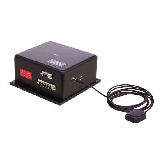
Mounting The DMS-SGP01 has four 0.15” diameter mounting holes for 6-32 screws (See Figure 1). If high shock loads are expected (greater than 10G or repeated shocks greater than 5G), appropriate shock mounting should be used to prevent damage. -
Page 5: Operation
The message can be read by using a terminal program or by using the terminal mode of Watson Industries’ communication software. The DMS can also be “re-initialized” after it has been turned on. This is especially useful if the sensor has been used in severe maneuvers that have over-ranged the angular rate sensors and caused significant errors to accumulate. -
Page 6: Free Mode
The maximum rate is 71.11 strings per second. See Appendix A for information on how to change the data string. The contents of a typical string are formed as follows: Watson Industries, Inc. DMS-SGP01 Rev B 03/22/2018... - Page 7 EEPROM of the unit (see Appendix A). In addition, more channels are available for output (see Appendix A). The system is protected from inadvertent write-over of the EEPROM by requiring two spacebar commands during the initialization interval to access the EEPROM or related functions. Watson Industries, Inc. DMS-SGP01 Rev B 03/22/2018...
-
Page 8: Rs-232 Input Commands
Command mode. This will also disable the logic input Reference Command and Free Mode Command until the next time the unit is powered up. Double spacebar at initialization is required for access to this command. Watson Industries, Inc. DMS-SGP01 Rev B 03/22/2018... -
Page 9: Analog Outputs
The outputs include: Signal Range Output Range 0 VDC Scale Factor ±180° Bank ±10V 0° 18°/s/V ±90° Elevation ±5V 0° 18°/s/V Heading ±10V 0° (North) 18°/s/V 0-360° ±100°/s Roll Rate (X Axis) ±10V 0°/s 10°/s/V Watson Industries, Inc. DMS-SGP01 Rev B 03/22/2018... -
Page 10: Analog Inputs
Leave pin open if not in use. Ground to command. NOTE: The digital logic inputs are all disabled if any one equivalent serial command is sent via RS-232. This is to prevent hardware/software conflicts. Watson Industries, Inc. DMS-SGP01 Rev B 03/22/2018... -
Page 11: Specifications
Acquisition time for GPS units is typical for the contiguous United States. Acquisition time may differ due to interference in your geographic area. † • Specifications are subject to change without notice. • This product may be subject to export restrictions. Please consult the factory. Watson Industries, Inc. DMS-SGP01 Rev B 03/22/2018... - Page 12 Z Axis Rate Analog Output No Connection • ** The user receives Power Ground & Signal Ground are electrically isolated • on this line. The signal ground is connected to case. FORWARD Figure 1 DMS-SGP01 Watson Industries, Inc. DMS-SGP01 Rev B 03/22/2018...
- Page 13 Figure 2 GPS Antenna Dimensions Watson Industries, Inc. DMS-SGP01 Rev B 03/22/2018...
- Page 14 DISCLAIMER The information contained in this manual is believed to be accurate and reliable; however, it is the user’s responsibility to test and to determine whether a Watson Industries’ product is suitable for a particular use. Suggestion of uses should not be taken as inducements to infringe upon any patents.
- Page 15 Customer Service All repairs, calibrations and upgrades are performed at the factory. Before returning any product, please contact Watson Industries to obtain a Returned Material Authorization number (RMA). Return Address & Contact Information Watson Industries, Inc. 3035 Melby Street Eau Claire, WI 54703...
- Page 16 Note: The Ground Track Velocity field is filled with asterisks when the data is invalid. (****.*) Note: The Latitude & Longitude fields are filled with asterisks when the data is invalid. (“+**.***** +***.*****”) Note: The Altitude field is filled with asterisks when the data is invalid. (*****) Watson Industries, Inc. DMS-SGP01 Rev B 03/22/2018...
- Page 17 Reset Not in Free Mode Bit 4 GPS Enabled Bit 3 Reset Not in Reference Mode Bit 2 Reset Bit 1 Reset Valid GPS velocity data Bit 0 Reset Valid GPS heading data Watson Industries, Inc. DMS-SGP01 Rev B 03/22/2018...
- Page 18 Type 'Y' or “y” to output channel, type 'N' or “n” to remove channel When you get to bottom of list, this message will appear: Y = GOBACK, N = INSTALL DATA & QUIT, Q = QUIT DO YOU WANT TO TRY TO SET DATA AGAIN? Watson Industries, Inc. DMS-SGP01 Rev B 03/22/2018...
- Page 19 To set the heading mode to Relative Heading type ‘2’. This is the normal DMS mode (non-GPS). In this mode, the GPS antennas do not need to be connected. To make any of these modes the default the next time you power the unit on type in " (a quote mark.) Watson Industries, Inc. DMS-SGP01 Rev B 03/22/2018...
- Page 20 To set to Analog Velocity type ‘2’. This is the normal DMS mode (non-GPS). Make sure that the proper analog velocity signal is applied. To make this selection the default the next time you power the unit on type in " (a quote mark.) Watson Industries, Inc. DMS-SGP01 Rev B 03/22/2018...
- Page 21 To turn on Altitude Correction type ‘1’. To shut off Altitude Correction type ‘2’. To make this selection the default the next time you power the unit on type in " (a quote mark.) Watson Industries, Inc. DMS-SGP01 Rev B 03/22/2018...
- Page 22 The values of Forward, Lateral and Vertical Acceleration should remain at the values when level. Repeat the test for the roll axis of the sensor. Under this test, Y and Z acceleration will read 0.71G and the X acceleration will retain its value at level. Watson Industries, Inc. DMS-SGP01 Rev B 03/22/2018...
- Page 23 100 °/sec limit. The sensor should then be rotated about the vertical and the Yaw output will respond accordingly. The test should then be repeated for the Roll axis. Watson Industries, Inc. DMS-SGP01 Rev B 03/22/2018...
- Page 24 0x80 0x99 0x99 0xCC Remove the most significant bit from each byte: Bank Elevation Heading X Rate Y Rate Z Rate 0x05 0x7E 0x70 0x03 0x7B 0x11 0x2A 0x1C 0x00 0x19 0x19 0x4C Watson Industries, Inc. DMS-SGP01 Rev B 03/22/2018...
- Page 25 For Angular Rates: Scale factor is: (200 ˚/sec) / 32768 counts Bank Elevation Heading X angular rate Y angular rate Z angular rate 14.991 ˚ -5.010 ˚ 315 ˚ 9.985 ˚/sec -15.015 ˚/sec 54.980 ˚/sec Watson Industries, Inc. DMS-SGP01 Rev B 03/22/2018...
- Page 26 Shift lower byte left once (to remove 1 bit space between bytes): X Accel Y Accel Z Accel X Rate Y Rate Z Rate 0x00 0x7E 0x79 0x03 0x7B 0x11 0x00 0x34 0xDC 0x32 0x32 0x98 Watson Industries, Inc. DMS-SGP01 Rev B 03/22/2018...
- Page 27 Z Accel X angular rate Y angular rate Z angular rate 0.0000g -0.2808g -0.9595g 9.985 ˚/sec -15.015 ˚/sec 54.980 ˚/sec 9600 Baud 8 Bit Data 1 Start Bit 1 Stop Bit No Parity Watson Industries, Inc. DMS-SGP01 Rev B 03/22/2018...
Need help?
Do you have a question about the DMS-SGP01 and is the answer not in the manual?
Questions and answers