
Related Manuals for bluefin PUPUSC-330SU-R


Summary of Contents for bluefin PUPUSC-330SU-R
- Page 1 PUPUSC-330SU-R Installation, Operation, & Maintenance Manual Submersible Sump Pumps PUPUSC-330SU-R...
- Page 2 Welcome Guide • English Contents: Before getting started, ensure the package contains the following components: • 1/3HP Submersible Cast Iron Sump Pump Recommended Tools: Recommended Supplies • Pressurized Fittings • Pipe fittings • Check Valve • Concrete • Trowel • Corrugated Pipe •...
-
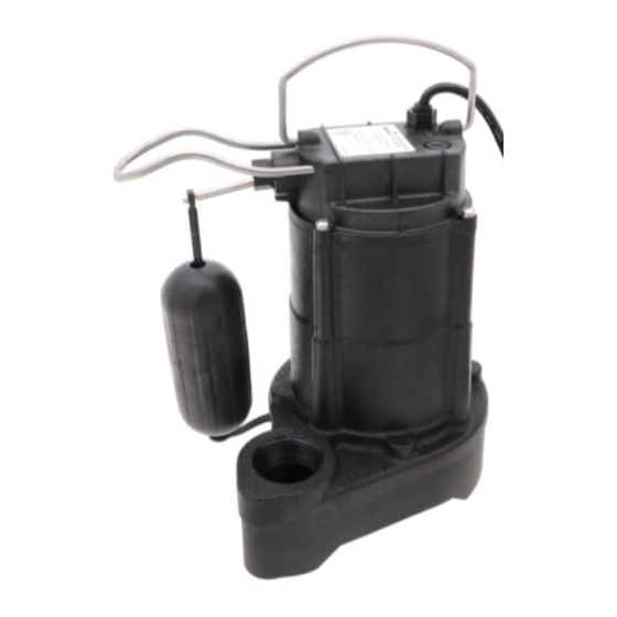
Page 3: Part List
Part List Parts Description Float rod Circlip Float Float holder Handle Motor Mechanical seal Impeller Circlip for shaft Volute Bolts... -
Page 4: Important Safeguards
IMPORTANT SAFEGUARDS Read these instructions carefully and retain them for future use. If this product is passed to a third party, then these instructions must be included. When using the product, basic safety precautions should always be followed to reduce the risk of injury including the following: •... -
Page 5: Installation
Installation Step 1: Inlet Pipe Sump Basin at least 14”diameter • If using a basin, place the pump directly on the bottom of the basin. To prevent damage set the pump on a solid, level surface. Do not place pump directly on clay, earth, gravel or sand. - Page 6 Installation Step 2: • Connectinga discharge pipe to the pump. Wrap the threads of the discharge Connecting the discharge pipe to the pump: Wrap the threads of the discharge Connecting a discharge pipe to the pump. Wrap the threads of the discharge pipe pipe with a 1/8”...
- Page 7 Installation Step 3: • Placing the pump in a basin and connecting the check valve: connect the discharge pipe (1) to the elbow (2), union(3),check valve(4), and gate valve(5). Position pump so the switch is away from the inlet, so switch is clear from NOTICE incoming water.
- Page 8 Installation Step 4: • Connecting power: Secure power supply cord to discharge pipe using cable or zip ties to prevent possible switch entanglement. Connect pump power supply cord to a ground fault circuit interrupter (GFCI) receptacle. Step 5: • Operating the pump: Fill the basin/pit with water,the pump will start when the Operating the pump: Fill the basin/pit with water.
-
Page 9: Safety Information
Installation Step 6: • Verify the switch is operating without any obstruction from the pump, piping and basin.15. Verify the switch is operating without any obstruction from the pump, piping and basin. Fill the basin/pit with water again. While the pump is draining the basin/pit, verify the Fill the basin/pit with water again. -
Page 10: Additional Safety Precautions
ADDITIONAL SAFETY PRECAUTIONS CAUTION • Know the pump applications, limitations, and potential hazards. • Make certain the electrical power source is adequate for the requirements of the pump. • ALWAYS disconnect the power to the pump and drain all water from the system before servicing. -
Page 11: Cleaning And Maintenance
Cleaning and Maintenance • The pump should be inspected 3-4 times per year for pump movement or buildup of debris on the switch or float. Reposition pump if it has moved. Remove any debris that could interfere with the operation of the switch. Lack of proper routine maintenance will void warranty. -
Page 12: Specifications
PUPUSC-330SU-R Specifications : PUPUSC-330SU-R ASIN : B07SPYCNST Property Specifications 115V / 60Hz Voltage Horsepower 1/3 HP Amps 6.2 A 30.4' (9.3 m) Maximum head height Maximum flow (GPH) 3680 U.S. GPH (13929 L/hr) 1-1/2" Discharge size 10’ (3 m) Power cord length (ft.) PERFORMANCE 5’...
Need help?
Do you have a question about the PUPUSC-330SU-R and is the answer not in the manual?
Questions and answers